
Analyzer
User Guide
Software Revision: 3.2
Document Revision: 3.24
Published: August 8, 2023

Copyright
The information contained in this User Guide regarding the use of
LogTag Analyzer software is intended as a guide and does not constitute
a declaration of performance. The information contained in this
document is subject to change without notice. Unless otherwise noted,
the example companies, organizations, email addresses and people
depicted herein are fictitious, and no association with any real
company, organization, email address or person is intended or should
be inferred. Complying with all applicable copyright laws is the
responsibility of the user.
No representation or warranty is given and no liability is assumed by
LogTag North America Inc with respect to the accuracy or use of such
information or infringement of patents or other intellectual property
rights arising from such use or otherwise.
Copyright © 2004-2023 LogTag North America Inc. All rights reserved.
https://logtag.com
Privacy Policy
LogTag North America Inc stores a small number of your personal data
to enhance your user experience. What data we store and the way we
store and use the data is described in our Privacy Policy, which you can
access from the LogTag North America Inc website at
https://logtag.com/privacy-policy. Installing and using this software
constitutes your agreement to this policy.
Disclaimer
LogTag
®
products assist with monitoring temperature and humidity
exposure, but do not monitor the quality of the goods they accompany.
Their purpose is to signal if product quality evaluation or further
testing is required.
Typographical Conventions
Text in this font refers to buttons on a LogTag
®
product.
Text in this font refers to actions to be taken in LogTag Analyzer, such
as clicking a button, icon or menu item.
Text in this font describes features of a LogTag
®
product.
An icon or menu in gray color cannot be clicked and its
function is not available at this time.
An icon or menu in the theme color can be clicked and its
function is available.
Text like this gives you tips on how to simplify tasks and how
to get extra information.
Text like this highlights notes and key information that you
should be aware of.
Text like this shows important information about issues that
could cause you to inadvertently lose data.
Text in this font refers to features, tabs or dialogue boxes.
Links or references to other part in this document appear like this.
Links to external web pages appear in this format.
About
LogTag
®
Analyzer User Guide
page 2

Table of Contents
Copyright 2
Privacy Policy 2
Disclaimer 2
Typographical Conventions 2
Table of Contents 3
List of Figures 5
List of Tables 7
LogTag Analyzer Software License 8
Introduction 10
The LogTag® Recording System 11
Loggers 12
Probes 12
Software 14
Interfaces 14
Installing the software 15
System requirements 15
macOS and Linux
.NET Framework 17
Getting a copy of the software 17
The installation process 19
Finding your software version 23
Upgrading LogTag Analyzer 24
Migrating from LogTag Analyzer Version 2 26
Using LogTag Analyzer 27
The User Interface 28
Menus and Toolbars 31
Menu commandsToolbar commandsPrint preview toolbar
The Status Bar 43
Dates and TimesUpload Status
Color Picker 45
Initial Set-up 46
Advanced Set-up 46
Connecting the Interface 47
Configuring a LogTag® product for recording 48
Command Buttons 50
Progress Pane 51
Working with more than one logger 52
User Related Configuration Parameters 53
DescriptionConfigure requires a passwordDownload requires a passwordBattery conditionRemaining StartsUpgrade logger
Logging Related Configuration Parameters 54
Start methodEnable pre-start loggingRecord maximum number of readingsRecord readings continuously, overwrite oldest when memory fullRecord readings so that:Readings recorded will span at least X daysNumber of readings to record (maximum is Y)Record a reading every XBegin recording after a delay of X
Configuring Alarms 57
Standard Alert Related Configuration ParametersAdvanced Alert SettingsAudible Alarm
Display Logger Advanced Settings 60
Clear and reset alarm when STOP/CLEAR button pressedAlarm remains on even if readings return to non-violation rangePause alarm/statistics processing for X readingsSwitch off display after 30 secondsShow total summary days collectedShow user resettable Min/Max (if supported)Allow logging stop with STOP buttonAllow reset of logger with START buttonEnable Quick start/stop if availableShow alarm screens during reviewAdditional Features for TRED30-16R and TRED30-16CP models
USB Logger File settings 66
Generate Data ListAlarm and Grid LinesShow Mean Kinetic Temperature (MKT)Regional SettingsChart ScalingFiles to generateUSB LoggersMulti-Alarms in USB Loggers
Updating USB Loggers 72
Wireless Connection Parameters 74
Using the LogTag® Online Connection Wizard
Using the LogTag Access Wizard 78
Quickly re-configuring a LogTag® logger 78
Automatic Re-Configuration after Download 79
Continuous operation 79
Pre-start data collection 80
Restricting Access 80
Protecting Recorded Data 81
Password Rules 81
Verify Access Password
Hibernation - Prolonging battery life 82
Starting and using the LogTag® logger 83
Configuration Profiles 84
Profiles GridProfile Control ButtonsProfile Storage File Name and PathProfile File ControlsProfile Dialogue Controls
Calibration Certificates 89
Smart Probes
Results from LogTag® Loggers 92
Progress Pane 93
LogTag® Data files 95
File generation for Dual-Channel loggersDigital signaturesHow secure are my dataViewing file properties
Saving a Multi Chart File 99
Selected LogTag® Data files (*.sltd) 99
Calling up previous results 100
Analyzing the results 101
Chart Display 103
The Chart Control PanelManual ScalingInspection and download mark zoomMulti Charts (Combining Charts into a Single View)
Dew Point 117
Theoretical backgroundApplication
Chart annotations 120
Adding AnnotationsEditing AnnotationsDeleting Annotations
Report Display 124
Multi Chart Reports
Data Display 127
Multi Chart Data Tab
Summary Display 130
Displaying statistics
Day Summary Display 131
LogTag® logger products with display
Printing the results 132
Page SetupPrinting a single documentPrinting multiple documents
Automatically calculated statistics 134
Average ReadingDegree MinutesMean Kinetic TemperatureStandard Deviation
Sharing recorded data with others 138
Sending a file by email directly from LogTag Analyzer 138
Automatic emailing and uploading to FTP sites 139
Saving a file for use in spreadsheets 140
CSV File exportXLS file exportUsing the Windows Clipboard
PDF files 141
Saving a file as text 141
LogTag® Data files (*.ltd) 142
About
LogTag
®
Analyzer User Guide
page 3

Integrating LogTag Analyzer with LogTag Online 143
Signing in 144
Working with multiple teams 144
Automatically uploading files to LogTag® Online 145
If your logger is attached to a locationIf your logger is not attached to a locationIf LogTag®Online is not available
Opening files directly from LogTag® Drive 146
Customizing the Software 147
General Settings 149
Show temperatures in...Default time interval to displayLanguageEnable automatic checking for a newer versionEnable USB Logger Update Check
Summary Statistics 152
Automatically calculate and display following dataDecimal PlacesStandard DeviationMean Kinetic TemperatureUse logger stored value (if defined)Ignore paused readings when calculating statistics
Chart Statistics 154
Display the following statistics in Chart Statistics annotations 154
Insert chart statistics annotation when a new document is created 154
Panel Transparency Setting 154
Annotation font defaults 154
Humidity statistics 154
Charts 155
Restore defaults 155
Heading 155
Chart defaults 155
Markers:Shaded areasGridlinesNon-validated readingsReadings beyond specifications
Chart Palette Colors 156
Default Zoom 157
Multi Chart Series ID 157
Auto-hide Chart Menu 157
Disable chart anti-aliasing 158
Reset all open documents 158
Dew Point Display 158
Zoom and Pan Controls 158
Mouse ZoomMouse PanWheel ZoomWheel Pan.
Automation 160
Enable automatic download of readings from LogTag® devices 160
Reconfigure with same settings after automatic download 160
Display readings after successful download 161
Only show the latest set of readings after download 161
Automatically save data files to default folder if source is read only 161
Always block low battery LogTags from Configuration 161
Automatic emailing and uploading to FTP sites 162
SMTP and email settingsFTP settings
File and Folder Settings 171
File Name 172
Folder Name 174
Display X items in my most recently used list 176
Display 176
Default File Format 176
Uniqueness 177
Auto-Save on Exit 178
Exports and Reports 179
Automatic file creationAttaching files to emailsCopying ChartsReport appearance
Date and Time Format 182
Time zones 183
Communication Ports 185
User Server 186
Activity Logs 188
LogTag® Online 190
Automatically sign in to LogTag® Online when Analyzer is startedAutomatically register loggers LogTag®after successful configurationUpload files to LogTag LogTag® when user is signed inStore pending uploads between sessions, automatically resume uploads on program start up.
Importing and Exporting Option Settings 191
Exporting the Options Settings 192
Importing the Option Settings 193
Appendix 195
Code Pages 196
Connecting to LogTag® User Server 199
How users log on 199
How users change their password 201
Connecting to Gmail 202
Office365 email support 205
Getting more help 206
Unsupported Loggers 208
Damaged Calibration 209
Recovering from a failed firmware update 210
Index 212
About
LogTag
®
Analyzer User Guide
page 4

List of Figures
Figure 1: Typical distribution process using loggers 11
Figure 2: Example of a stationary loggers application 11
Figure 3: Some of the LogTag® logger products 12
Figure 4: Selection of external probes for LogTag® loggers 12
Figure 5: Smart Probe model CP100 13
Figure 6: TRED30 in standard USB interface cradle LTI/USB 14
Figure 7: LogTag® USB Interface LTI-HID 14
Figure 8: LogTag® USB Interface LTI-HID
Figure 9: Downloading using Internet Explorer 17
Figure 10: Download Window - Mozilla Firefox 17
Figure 11: Download progress using IE 18
Figure 12: Download progress using Firefox 18
Figure 13: Download progress using Chrome 18
Figure 14: About LogTag Analyzer 23
Figure 15: Checking for a software update 24
Figure 16: Downloading the Update 24
Figure 17: Ready to install 25
Figure 18: The workspace 28
Figure 19: Workspace with two files open 29
Figure 20: Multiple floating windows 30
Figure 21: Menu and toolbar 31
Figure 22: File menu 32
Figure 23: LogTag Analyzer Edit menu 34
Figure 24: LogTag Menu 35
Figure 25: LogTag Online Menu 36
Figure 26: Window menu 37
Figure 27: User Server menu 38
Figure 28: Help menu 39
Figure 29: LogTag Analyzer toolbar 40
Figure 30: Print preview 42
Figure 31: Status bar showing one pending email. 44
Figure 32: Basic Color Selection 45
Figure 33: Advanced Color Selection 45
Figure 34: Rear of PC with 4 USB ports 47
Figure 35: Locating loggers and loading initial parameters 48
Figure 36: LogTag Menu Configure 48
Figure 37: Configuration screen for a HAXO-8 49
Figure 38: Progress Pane Indicator 51
Figure 39: Logger configured 51
Figure 40: Logger configured
Figure 41: Advanced Alert Settings - Sample settings 60
Figure 42: Advanced alert options for display loggers 61
Figure 43: Inspection alarms and fridge/freezer symbols 63
Figure 44: CP110 Smart Probe for TRED30-16CP Loggers 64
Figure 45: File Settings tab for USB loggers 66
Figure 46: Alarm ranges for USRIC-8M 69
Figure 47: Representation in LogTag Analyzer 69
Figure 48: Entry line for alarm trigger conditions 70
Figure 49: Entry line for RH alarm trigger conditions 70
Figure 50: Alarm ranges for UTRID-16 71
Figure 51: Representation for UTRID-16 71
Figure 52: An update is available for a USB logger 72
Figure 53: The update has successfully completed 73
Figure 54: WiFi Settings tab for units without a WLAN configuration 74
Figure 55: Available wireless networks 75
Figure 56: WiFi Settings tab 76
Figure 57: LogTag Access Wizard from toolbar 78
Figure 58: LogTag Access Wizard from menu 78
Figure 59: LogTag® quick-reconfigure function 78
Figure 60: Confirmation request to allow stopping the logger 79
Figure 61: Password entry 80
Figure 62: Password confirmation 82
Figure 63: Hibernating a logger 82
Figure 64: Hibernating multiple loggers 83
Figure 65: LogTag Profile Menu 84
Figure 66: Configuration Profiles Main Window 84
Figure 67: Profiles in the profile grid 85
Figure 68: New profile window 85
Figure 69: Editing a TRIX-8 profile 86
Figure 70: Prompt when overwriting an existing Profile 86
Figure 71: Factory Calibration Certificate 89
Figure 72: Calibration certificate with multiple tabs 90
Figure 73: Probe calibration was adjusted 91
Figure 74: Downloading a LogTag® automatically 92
About
LogTag
®
Analyzer User Guide
page 5

Figure 75: Download Menu 93
Figure 76: Wizard Toolbar Icon 93
Figure 77: Progress Pane when downloading data 93
Figure 78: Downloading a LogTag®logger 94
Figure 79: No Readings to download! 95
Figure 80: Digital Signatures toolbar button 96
Figure 81: File properties Menu 98
Figure 82: File properties 98
Figure 83: File Open dialogue window 100
Figure 84: File not compatible withcurrent version of LogTag Analyzer 100
Figure 85: View tabs and reading range selection 101
Figure 86: Chart display 103
Figure 87: Chart display while zooming with the mouse 104
Figure 88: Upper Chart Control Panel 105
Figure 89: Lower Chart Control Panel 106
Figure 90: Manual scaling window 107
Figure 91: Seven charts combined into a multi chart 111
Figure 92: Shortcut Menu after right-clicking on chart area 112
Figure 93: Shifting a chart 114
Figure 94: Warning: Too many charts open 115
Figure 95: Multi chart data - as recorded 116
Figure 96: Multi chart data - normalized 116
Figure 97: Multi chart data - normalized min/max/average curves 116
Figure 98: Formula used for dew point 117
Figure 99: Approximate dew point error for humidity/temperature 118
Figure 100: Chart Right-Click Menu 120
Figure 101: Chart Annotation Panel 120
Figure 102: Advanced View of the Annotations Panel 122
Figure 103: Chart with different types of annotations 123
Figure 104: Report Tab 124
Figure 105: Receiver Notes Entry Dialogue 124
Figure 106: Data tab 127
Figure 107: Multi chart data tab 129
Figure 108: Multi chart data tab
Figure 109: Statistics tab with summary for all readings 130
Figure 110: Statistics tab when inspection marks are included 130
Figure 111: Day summary for loggers with display and statistics memory 131
Figure 112: Page Setup Window 132
Figure 113: Printer dialogue 132
Figure 114: Formula for average reading 134
Figure 115: Formula for degree minutes 135
Figure 116: Formula for mean kinetic temperature 136
Figure 117: Sample based standard deviation 137
Figure 118: Population based standard deviation 137
Figure 119: Send Mail Toolbar Icon 138
Figure 120: Active and inactive Upload Toolbar Icon 139
Figure 121: PDF Export Settings 141
Figure 122: Sign in window 144
Figure 123: Team selection for your account 144
Figure 125: Edit Options Menu 148
Figure 126: Toolbar Icon 148
Figure 127: General settings 149
Figure 128: A software update is available 150
Figure 129: Statistics Options dialogue 152
Figure 130: Chart Statistics Options dialogue 154
Figure 131: Chart options 155
Figure 132: Custom range selection window 157
Figure 133: Anti-Aliasing turned on 158
Figure 134: Anti Aliasing turned off 158
Figure 135: Automation Options dialogue 160
Figure 136: Selection of FTP and SMTP activity 162
Figure 137: SMTP settings for automatic emailing 163
Figure 138: Error message 165
Figure 139: Basic FTP settings screen 166
Figure 140: Error during communication with the FTP server 167
Figure 141: File and folder settings Option dialogue 171
Figure 142: Available file name elements 172
Figure 143: List of available variables 174
Figure 144: Export Options 179
Figure 145: Customizing Export Options 180
Figure 146: List of file formats for attaching via Sendmail. 181
Figure 147: Date and time options 182
Figure 148: All COM ports disabled, USB enabled 185
Figure 149: Running LogTag Analyzer as administrator 186
Figure 150: User Server options 187
Figure 151: Configuration logging options 188
Figure 152: Parameters available for Configuration logging 189
Figure 153: Parameters available for Download logging 189
About
LogTag
®
Analyzer User Guide
page 6

Figure 154: LogTag Online Option Settings 190
Figure 155: Selecting the options settings to be exported 192
Figure 156: Selecting the export file name and location 192
Figure 157: Successfully exported settings file 192
Figure 158: Import options dialogue 193
Figure 159: Import successful 193
Figure 160: ASCII Table of printable characters 196
Figure 161: Code page 847, Thai language 196
Figure 162: Code page 1252, Western languages 196
Figure 163: Accessing charmap.exe on Windows 10 197
Figure 164: Code page 932, Japanese language, subset 91 198
Figure 165: Code page 932, Japanese language 198
Figure 166: Logon request when connected to User Server 199
Figure 167: Unable to log on to User Server software 199
Figure 168: Changing a User Server password 201
Figure 169: Gmail settings selected 202
Figure 170: Enter your Gmail account details 203
Figure 171: Confirming the account password 203
Figure 172: Giving LogTag Analyzer permission to send email on your behalf 204
Figure 173: Success message 204
Figure 174: Successfully connected to the Gmail SMTP server 204
Figure 175: Time-out from SMTP server 204
Figure 176: Settings for Outlook 365 205
Figure 177: Requesting Help via the Help Menu 206
Figure 178: Diagnostics email message 207
Figure 179: Software update is available for an unrecognized file or logger. 208
Figure 180: Latest software is already installed - a diagnostics email is required 208
Figure 181: Logger containing invalid calibration details 209
Figure 182: Discovering loggers requiring a recovery process 210
Figure 183: Recovery on progress 210
Figure 184: Logger recovery successful 211
Figure 185: Logger recovery failed 211
List of Tables
Table 1: File menu - available commands 32
Table 2: Edit menu - available commands 34
Table 3: LogTag menu - available commands 35
Table 4: LogTag Online menu - available commands 36
Table 5: Window menu - available commands 37
Table 6: User Server menu - available commands 38
Table 7: Help menu - available commands 39
Table 8: Toolbar icons and their function 40
Table 9: Commands available in the print preview toolbar 42
Table 10: Time zones for data display 44
Table 11: Alert examples 58
Table 12: Advanced alert examples 60
Table 13: Profile error messages 88
Table 14: View Tab summary 101
Table 15: Reading range selection 101
Table 16: Additional information for Charts 106
Table 17: Basic annotation options 120
Table 18: Appearance settings 122
Table 19: Calculated Statistics 152
Table 20: SMTP Server settings 163
Table 21: Email settings 164
Table 22: Additional settings 165
Table 23: FTP Server settings 166
Table 24: Firewall/Proxy settings 167
Table 25: File format settings 167
Table 26: Additional settings 168
Table 27: Description of available file name elements and their place holder text 172
Table 28: Available elements and their placeholder text for the storage folder 174
Table 29: Date options 182
Table 30: Time options 183
About
LogTag
®
Analyzer User Guide
page 7

To use the software (defined below) you must agree to the license terms set out below, including the
LogTag North America Inc privacy policy as published on http://lt.help/wq1ms.
Last updated: July 21, 2023
LogTag Analyzer License
===========================
LOGTAG NORTH AMERICA INCORPORATED END-USER LICENSE AGREEMENT
YOU SHOULD CAREFULLY READ THE FOLLOWING TERMS AND CONDITIONS BEFORE USING THIS
PRODUCT. IT CONTAINS SOFTWARE, THE USE OF WHICH IS LICENSED BY LOGTAG NORTH AMERICA INC,
TO ITS CUSTOMERS FOR THEIR USE ONLY AS SET FORTH BELOW. IF YOU DO NOT AGREE TO THE TERMS
AND CONDITIONS OF THIS AGREEMENT AND TO THE PRIVACY POLICY AS PUBLISHED ON THE LOGTAG
WEBSITE DO NOT USE THE SOFTWARE. BY ACCESSING OR OTHERWISE USING ANY PART OF THE
SOFTWARE YOU INDICATE THAT YOU ACCEPT THESE TERMS ON BEHALF OF YOURSELF AND ANY
ORGANIZATION OR COMPANY YOU REPRESENT (TOGETHER, "YOU").
LICENSE: LogTag North America Inc grants you a revocable, limited, non-exclusive, non-transferable
(except as set forth herein), non-sublicensable, non-assignable (except as set forth herein) license to use
the accompanying software program(s) (the "Software") subject to the terms and restrictions set forth in
this License Agreement and solely for your internal business or personal purposes. You are not permitted
to lease or rent (except under separate mutually agreeable terms set forth in writing), distribute or
sublicense the Software or to use the Software in a time-sharing arrangement or in any other unauthorized
manner. Further, no license is granted to you in the human readable code of the Software (source code).
Except as provided below, this License Agreement does not grant you any rights to patents, copyrights,
trade secrets, trademarks, or any other rights in respect to the Software.
The Software is licensed to be used on any computing device. You may reproduce and provide one (1) copy
of such Software for each computing device on which such Software is used as permitted hereunder.
Otherwise, the Software and supporting documentation may be copied only as essential for backup or
archive purposes in support of your use of the Software as permitted hereunder. You must reproduce and
include all copyright notices and any other proprietary rights notices appearing on the Software on any
copies that you make.
NO ASSIGNMENT; NO REVERSE ENGINEERING: You may transfer the Software and this License Agreement
to another party if the other party agrees in writing to accept the terms and conditions of this License
Agreement. If you transfer the Software, you must at the same time either transfer all copies of the
Software as well as the supporting documentation to the same party or destroy any such materials not
transferred. Except as set forth above, you may not transfer or assign the Software or your rights under
this License Agreement.
Modification, reverse engineering, reverse compiling, or disassembly of the Software is expressly
prohibited. Analyzing the input to and output from the Software is expressly prohibited except when this is
done solely to evaluate the subjective quality of the Softwareʼs visual and data analysis processes for your
own internal business purposes. You may not otherwise modify, alter, adapt, port, or merge the Software
except as specified in this License Agreement.
EXPORT RESTRICTIONS: You agree that you will not export or re-export the Software or accompanying
documentation (or any copies thereof) or any products utilizing the Software or such documentation in
violation of any applicable laws or regulations of the United States or the country in which you obtained
them.
TRADE SECRETS; TITLE: You acknowledge and agree that the structure, sequence and organization of the
Software are the valuable trade secrets of LogTag North America Inc and its suppliers. You agree to hold
such trade secrets in confidence and to protect the Software as you would your own confidential
information, but with no less than reasonable care. You further acknowledge and agree that ownership of,
and title to, the Software and all derivatives, modifications, improvements, and subsequent copies thereof
regardless of who made them, when they are or were made, and the form or media in which they are made,
are held by LogTag North America Inc and its suppliers.
TRADEMARKS AND COPYRIGHTS: "LogTag®" is a registered trademark (R) of LogTag North America Inc.
You may not remove, alter, deface, overprint, or otherwise obscure any LogTag North America Inc
trademark, service mark, or copyright notices included with this Software.
INTELLECTUAL PROPERTY; THIRD PARTY SOFTWARE: The Software, and all modifications or derivatives
thereof and improvements thereto, and all intellectual property rights therein and thereto are and shall
remain in LogTag North America Inc. Except for the limited license granted to you in the section entitled
"License", this License Agreement does not transfer or convey to you or any third party any right, title, or
interest in or to the Software or any intellectual property rights therein. The Software may contain software
governed by license from third parties ("Third Party Software"), including, without limitation, any software
component that is subject to any open-source copyright license agreement ("Open Source").
Notwithstanding anything contrary herein, all Third Party Software is licensed to You solely under the
terms of the corresponding third party license agreement(s), if applicable. LogTag North America Inc
makes no representation or warranty concerning Third Party Software, including, without limitation, any
Open Source, and has no obligation or liability with respect to any Third Party Software, including, without
limitation, any Open Source.
PRIVACY POLICY: To use this software you must agree to the privacy policy as set forth on the LogTag
website at http://lt.help/wq1ms. This policy is subject to changes and you should review this periodically.
TERM AND TERMINATION: This License Agreement is effective until terminated. You may terminate it at
any time by destroying the Software and documentation together with all copies and merged portions in
any form. It will also terminate immediately if you fail to comply with any term or condition of this License
Agreement. Upon such termination you agree to destroy the Software and documentation, together with all
copies and merged portions in any form.
GOVERNING LAW: This License Agreement shall be governed by the laws of the State of California and by
the laws of the United States, excluding their conflicts of law principles. The United Nations Convention on
Contracts for the International Sale of Goods (1980) is hereby excluded in its entirety from application to
this License Agreement.
LIMITED WARRANTY; LIMITATION OF LIABILITY: EXCEPT AS EXPRESSLY PROVIDED OTHERWISE IN A
WRITTEN AGREEMENT BETWEEN LOGTAG NORTH AMERICA INC AND YOU, THE SOFTWARE IS NOW
PROVIDED "AS IS" WITHOUT WARRANTY OF ANY KIND, EITHER EXPRESS OR IMPLIED, INCLUDING, BUT
NOT LIMITED TO, THE IMPLIED WARRANTIES OF MERCHANTABILITY OR FITNESS FOR A PARTICULAR
PURPOSE, OR THE WARRANTY OF NON-INFRINGEMENT. WITHOUT LIMITING THE FOREGOING, LOGTAG
NORTH AMERICA INC MAKES NO WARRANTY THAT (I) THE SOFTWARE WILL MEET YOUR REQUIREMENTS,
(II) THE USE OF THE SOFTWARE WILL BE UNINTERRUPTED, TIMELY, SECURE, OR ERROR-FREE, (III) THE
RESULTS THAT MAY BE OBTAINED FROM THE USE OF THE SOFTWARE WILL BE ACCURATE OR RELIABLE,
(IV) THE QUALITY OF THE SOFTWARE WILL MEET YOUR EXPECTATIONS, (V) ANY ERRORS IN THE
SOFTWARE WILL BE CORRECTED, AND/OR (VI) YOU MAY USE, PRACTICE, EXECUTE, OR ACCESS THE
SOFTWARE WITHOUT VIOLATING THE INTELLECTUAL PROPERTY RIGHTS OF OTHERS. SOME STATES OR
JURISDICTIONS DO NOT ALLOW THE EXCLUSION OF IMPLIED WARRANTIES OR LIMITATIONS ON HOW
LONG AN IMPLIED WARRANTY MAY LAST, SO THE ABOVE LIMITATIONS MAY NOT APPLY TO YOU. IF
TEXAS LAW IS NOT HELD TO APPLY TO THIS AGREEMENT FOR ANY REASON, THEN IN JURISDICTIONS
WHERE WARRANTIES, GUARANTEES, REPRESENTATIONS, AND/OR CONDITIONS OF ANY TYPE MAY NOT
BE DISCLAIMED, ANY SUCH WARRANTY, GUARANTEE, REPRESENTATION AND/OR WARRANTY IS: (1)
HEREBY LIMITED TO THE PERIOD OF EITHER (A) THIRTY (30) DAYS FROM THE DATE OF OPENING THE
PACKAGE CONTAINING THE SOFTWARE OR (B) THE SHORTEST PERIOD ALLOWED BY LAW IN THE
APPLICABLE JURISDICTION IF A THIRTY (30) DAY LIMITATION WOULD BE UNENFORCEABLE; AND (2) THE
SOLE LIABILITY OF LOGTAG NORTH AMERICA INC FOR ANY BREACH OF ANY SUCH WARRANTY,
GUARANTEE, REPRESENTATION, AND/OR CONDITION SHALL BE TO PROVIDE YOU WITH A NEW COPY OF
THE SOFTWARE.
IN NO EVENT SHALL LOGTAG NORTH AMERICA INC OR ITS SUPPLIERS BE LIABLE TO YOU OR ANY THIRD
PARTY FOR ANY DIRECT, SPECIAL, INCIDENTAL, INDIRECT OR CONSEQUENTIAL DAMAGES OF ANY KIND,
OR ANY DAMAGES WHATSOEVER, INCLUDING, WITHOUT LIMITATION, THOSE RESULTING FROM LOSS OF
USE, DATA OR PROFITS, WHETHER OR NOT LOGTAG NORTH AMERICA INC HAD BEEN ADVISED OF THE
POSSIBILITY OF SUCH DAMAGES, AND ON ANY THEORY OF LIABILITY, ARISING OUT OF OR IN
CONNECTION WITH THE USE OF THE SOFTWARE. SOME JURISDICTIONS PROHIBIT THE EXCLUSION OR
About
LogTag
®
Analyzer User Guide
page 8
LogTag Analyzer Software License

LIMITATION OF LIABILITY FOR CONSEQUENTIAL OR INCIDENTAL DAMAGES, SO THE ABOVE LIMITATIONS
MAY NOT APPLY TO YOU. THESE LIMITATIONS SHALL APPLY NOTWITHSTANDING ANY FAILURE OF
ESSENTIAL PURPOSE OF ANY LIMITED REMEDY.
SEVERABILITY: In the event any provision of this License Agreement is found to be invalid, illegal or
unenforceable, the validity, legality and enforceability of any of the remaining provisions shall not in any
way be affected or impaired and a valid, legal and enforceable provision of similar intent and economic
impact shall be substituted therefore.
ENTIRE AGREEMENT: This License Agreement sets forth the entire understanding and agreement between
you and LogTag North America Inc, supersedes all prior agreements, whether written or oral, with respect
to the Software, and may be amended only in a writing signed by both parties.
The software menus and texts as well as this agreement have been created in English and any other
language versions have been translated from the English version. In the event of a dispute, reference
should be made to the English language version, which is conclusive.
For further information about licensing or the privacy policy please email [email protected].
About
LogTag
®
Analyzer User Guide
page 9

Chapter 1
Introduction
LogTag Analyzer version 3 is the latest LogTag
®
software, using Microsoft’s .NET technology.
It will allow easier integration into third-party developments and enables a path for supporting modern operating systems and multiple computing
platforms in the future, such as Linux or macOS.
If you are familiar with LogTag Analyzer version 2.x, you will find it easy to make the transition to version 3.x. There are a few new concepts, which you
can find by browsing the pages in this User Guide. The main differences are listed in the introductory guide What's new in LogTag Analyzer 3, available
from https://logtag.com.
This guide will take you through the relevant steps to successfully use the LogTag
®
products. You will learn how to:
l
install the software
l
configure LogTag
®
products for recording
l
retrieve the recorded readings
l
display and analyze the data
l
configure the available options in the software so you can make best use of its features.
If you are an experienced users of a previous versions, you may skip some of the early chapters. If, however, you are about to use a newer version of a
LogTag
®
product or Interface Cradle we recommend you at least skim the installation chapter for any relevant changes.
This guide covers version 3.2 release 4 of the LogTag Analyzer software. If you are unsure which version you are currently using, please read the section
about Finding your software version on page23.
If you find a feature described in this guide that does not appear in your software, we recommend you update it as explained in the section about
Upgrading LogTag Analyzer on page24. You can always get the most up to date version of LogTag Analyzer from the LogTag North America Inc website
at https://logtag.com.
This guide includes all the relevant information to install and use the product range supplied by LogTag North America Inc, however, the reader is
expected to be familiar with using a computer and the Windows
®
operating system.

Figure 1: Typical distribution process using loggers
LogTag North America Inc offer a range of logger products for temperature and humidity,
which are complemented by software and interface products. Some of these products can be
used on their own, most often, however, you will use a combination of products to get the best
results.
LogTag North America Inc offer a variety of different models. The product range is constantly
being updated and new models added, so visit the LogTag Website at https://logtag.com
frequently to get the latest information and news about upcoming product releases.
Typically LogTag
®
products are configured, put with goods that require monitoring and are
downloaded once the goods reach their intended destination.
Figure 2: Example of a stationary loggers application
Other applications may involve stationary loggers placed in warehouses or fridges, such as the
vaxtag®, as can be seen here.
Introduction
LogTag
®
Analyzer User Guide
page 11
The LogTag
®
Recording System

Figure 3: Some of the LogTag
®
logger products
Loggers
LogTag
®
temperature and humidity logger products are small, battery powered, credit card size
devices with built-in sensors and data logging memory. They record between 4,000 and 16,000
samples from anywhere between -80°C and +100°C, depending on the model. For detailed
information about each product visit the LogTag North America Inc website at
https://logtagrecorders.com/product-range/.
Figure 4: Selection of external probes for LogTag
®
loggers
Probes
LogTag North America offer a range of probes featuring different tips and different lead
lengths. The blue-sleeved probes from the ST100 family are used with standard external-probe
temperature loggers, while green-sleeved ST10 probes complement the range of low-
temperature loggers.
Introduction
LogTag
®
Analyzer User Guide
page 12

Figure 5: Smart Probe model CP100
Smart Probes are the latest addition to the range, and can be used with select external loggers,
such as the latest generation of UTRED30-WiFi and TRED30-16CP loggers. These probes can be
calibrated independent of the logger, reducing down time as the probes can simply be swapped
without the need to return the logger for calibration.
Introduction
LogTag
®
Analyzer User Guide
page 13

Software
Loggers are downloaded using the LogTag Analyzer software, which is also used to configure
loggers. This User Guide explains in detail how to configure and download loggers, how to
customize the settings and how to analyze and share the data.
Figure 6: TRED30 in standard USB interface cradle LTI/USB
Figure 7: LogTag
®
USB Interface LTI-HID
Interfaces
Unless your product is one of the USB Loggers you will need an interface to communicate
between the logger and the computer.
Most products use the standard interface cradle, where the LogTag
®
logger is inserted into the
slot from the top as shown to enable communication. You will be able to see the contact pins
inside the slot that meet with the matching contact pads on the LogTag
®
unit. When inserting
a LogTag
®
logger into the slot you feel a slight resistance as the contacts engage. Removing the
logger will cause a slight clicking noise as the contacts snap back into their unloaded position.
New in 2018, the LTI-HID is the next generation USB interface that can be installed without
requiring a proprietary driver. It also features two indicators at the top (red & green), which
identify what actions the interface is currently performing.
Introduction
LogTag
®
Analyzer User Guide
page 14

Installing the software
To use your LogTag
®
products you need to install LogTag Analyzer on your computer. This will allow preparing your LogTag
®
devices for recording,
downloading, analyzing and sharing the data.
Experienced users may choose to skip this chapter. You should read it, however, if you are new to using a computer or installing software.
System requirements
To ensure that the software will work on your computer following minimum specifications are required:
l
PC capable of running Windows
®
8 or later, or Windows
®
Server 2008 R2 SP1 or later. Although you may be able to install the software on earlier
operating systems by installing some of the prerequisites manually, only operating systems currently supported by Microsoft should be considered
for installing LogTag Analyzer.
l
Operating System must support .NET version 4.7.2
1
l
180MB free disk space (plus 2.5GB if .NET is not yet installed)
l
Internet Explorer 8.0 or later
l
1 available USB port to connect an interface or USB logger
l
1366 x 768, or higher, screen resolution
2
l
65535 screen colors
If you wish to use LogTag
®
Online with LogTag Analyzer you will also need a supported browser and an internet connection, please refer to the
LogTag
®
Online help file available from https://logtagonline.com/support.
If you are unsure of your computer's specifications, please refer to your operating system's documentation or help function.
macOS and Linux
There are no native applications for these operating systems. Both Linux and macOS offer several virtualization options, though, which allow you to
run Windows software.
Linux offers Virtualbox or QEMU virtualization software, which are both free.
You can use several commercial virtualization programs on macOS, on both Intel86 and ARM based MAC's. VMWare Fusion and Parallels Desktop are
both paid solutions, with VMWare also offering a free tier. A free option is also available (UTM, based on QEMU), but is not as easy to set up as the
1
LogTag Analyzer cannot be installed on Windows 10 versions prior to 1607 as these do not support .NET version 4.7.2.
2
Note that LogTag Analyzer works best if the operating system's display magnification has been set to 100%. When using a laptop in combination with an external screen, please ensure magnification for both is set to
the same value.
Introduction
LogTag
®
Analyzer User Guide
page 15
paid versions. At the time the user guide is published, Virtualbox is available for Intel86 based computers, but not for ARM based M1 and M2 devices.
Generally, all virtualization solutions have been tested and work well.
If you run either of those operating systems, please discuss the best option with your network administrator or contact our support.
Introduction
LogTag
®
Analyzer User Guide
page 16
.NET Framework
LogTag Analyzer version 3 is designed around Microsoft’s .NET 4.7.2 framework. To install and
run LogTag Analyzer you need a PC with at least a Windows 7 operating system.
The .NET framework 4.7.2 will likely be installed on most PCs, which had regular updates
applied via Windows Update. On some PC's with Windows 7 Microsoft’s .NET 4.7.2 Framework
will need to be installed. The LogTag Analyzer Installer can determine the presence of the
framework and will automatically download the framework directly from Microsoft, if it is not
already present on the PC. In this case your PC will need to be connected to the internet to
successfully complete the installation. This installation method will be suitable for single PC
installations.
If you wish to install this version on more than one computer without .NET 4.7.2, you can
download a standalone installer directly from Microsoft from this link: .NET Framework Offline
Installer (external link)
Getting a copy of the software
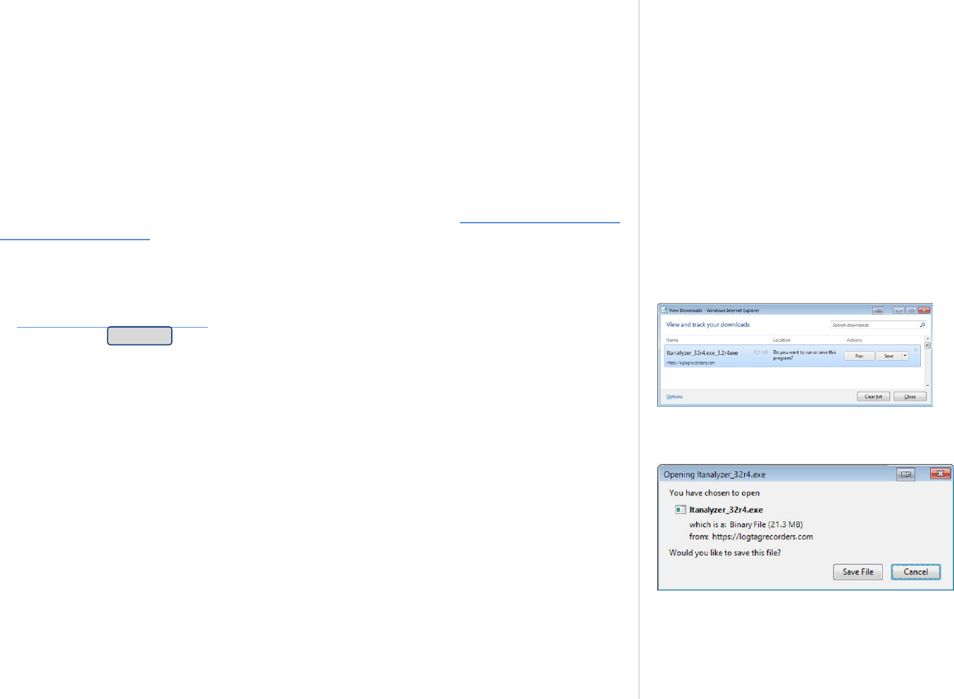
Figure 9: Downloading using Internet Explorer
Figure 10: Download Window - Mozilla Firefox
The software can be download from the from the LogTag North America Inc website; navigate
to logtagrecorders.com/software and click the LogTag Analyzer 3 link. Complete the registration
details and click Download.
LogTag Analyzer is available for download in a number of different formats:
l
ltanalyzer_32r4.exe
This is a single executable installer file and the most popular option; no other files are
required for installation of LogTag Analyzer software on your computer.
l
ltanalyzer_32r4.msi
This file is used by Network Administrators - it requires additional files and is best suited
when distributing the software remotely to a number of PC's.
l
ltanalyzer_32r4.zip
You can download a zipped version of the file, which has a smaller download size. You will
need an unzipping tool such as Unzip
®
to extract the single executable installer.
l
ltanalyzer_32r4.iso (on request)
The ISO file can be used to generate a CD, if you need to distribute the software to PC's
without a network connection.
Click on the desired download link. Depending on the type of browser and its version you may
get different windows to start and process the download. Modern browsers like Edge, Internet
Explorer, Google Chrome or Mozilla Firefox typically have a special directory into which all
downloads are copied, but you can also select your own.
Introduction
LogTag
®
Analyzer User Guide
page 17

Figure 11: Download progress using IE
Figure 12: Download progress using Firefox
Figure 13: Download progress using Chrome
LogTag North America Inc does not charge for the download and use of this software, or for
updates. You are welcome to distribute copies of the LogTag Analyzer software provided it is
distributed unaltered, in the packaged format as originally downloaded from the LogTag
Analyzer web page. Please refer to the LogTag Analyzer Software License (on page8).
Introduction
LogTag
®
Analyzer User Guide
page 18
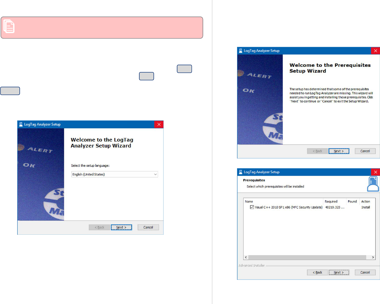
The installation process
You will require local administrator permissions for the PC on
which you are installing LogTag Analyzer.
To install the LogTag Analyzer software, locate the installation file
downloaded in the previous step and execute it (typically by double
clicking or selecting the file in Windows
®
Explorer and pressing Enter).
To proceed through each step of the installation process, click Next. If
you want to change a previous step you can click Back. At any stage
during the process, if you want to stop installing the software, click
Cancel.
1. Select the installer language
2. The software now checks that all prerequisite software packages
are present. These include the .NET framework and the Visual
C++ runtime libraries redistributable package.
The .NET framework is included in all supported operating
systems which are up to date with the latest updates. If not, you
will be asked to download and install the framework, as it is not
included in the installer package.
The Visual C++ runtime libraries may already be installed, as they
are used for many other commercial software. They are included
in the installer package, and you will be asked to permit their
installation, otherwise the installer will abort.
Introduction
LogTag
®
Analyzer User Guide
page 19

Once the installation is complete, click Finish and continue with
the installation of LogTag Analyzer.
3. Accept the Welcome screen by clicking Next.
4. Accept the End-User License Agreement and click Next
5. Select the installation folder. You can type a folder name or
browse to an existing folder. If the folder does not exist, it will be
created for you.
Introduction
LogTag
®
Analyzer User Guide
page 20

You can change the document storage location in LogTag
Analyzer 's option settings once you have started the
program, but you cannot change the program location.
We recommend you leave all options at their default
setting, especially if you are unsure of what option to
select or what effects changing the option would have.
You can also select where you want the downloaded data from
loggers to be stored. If you select LogTag Data will only be
accessible by me, the default folder will be created in your
Documents folder, and other users of the same PC will not have
access to the data.
If you select LogTag Data will be accelerate by all users of this
computer, this file location will be created in the Public
Documents folder.
6. Select, which files you wish to associate with LogTag Analyzer
(these files will, for example, automatically open in LogTag
Analyzer when you double-click them in Windows Explorer).
l
If you are installing LogTag Analyzer for the first time we
suggest you select all file types.
l
If you are upgrading from version 2, and you do not wish to
use version 2 any longer, you should also select all file types.
l
If you are upgrading from version 2, and you are planning on
operating both versions, you can decide if you wish to
associate the files in the right column with the new version
(select those file types) or leave them associated with the
older version (clear those file types).
You can change this later by right-clicking a file, and clicking
Open with.
During the first installation, you can also select the default
temperature units to be either °C or °F.
Again, you can change this later in "General Settings".
Click Next once you have made your selection.
7. The installer now has all the information and is ready to proceed.
Click Install to start the installation.
Introduction
LogTag
®
Analyzer User Guide
page 21

8. The installer is copying the required files to your PC.
9. When the installation is complete, click Finish to exit the
installer program.
The drivers required to operate your USB interface are installed as part
of the main installation process. From time to time updated drivers
may be released by LogTag North America Inc. These drivers will be
available through the Microsoft Windows
®
Update feature, as an
optional hardware update, or as part of an upgraded installer file (see
Upgrading LogTag Analyzer on page24).
Once the installation process has completed the installer file is no
longer required and can safely be deleted.
Introduction
LogTag
®
Analyzer User Guide
page 22

Finding your software version
Figure 14: About LogTag Analyzer
Click About LogTag Analyzer...from the Help Menu to display the About window.
This window displays the full version number of the software being used. You can use this to
check if the same software version is installed on multiple computers or to find out which user
guide to use.
When the software is updated, the version number of the software is increased.
You can also find major and minor version of LogTag Analyzer in the title bar:
Introduction
LogTag
®
Analyzer User Guide
page 23

Upgrading LogTag Analyzer
Figure 15: Checking for a software update
Figure 16: Downloading the Update
LogTag North America Inc will publish updates to LogTag Analyzer to introduce new or
enhanced features, or to support new LogTag
®
models. LogTag North America Inc recommend
that you always use the latest version of the software.
When you first install LogTag Analyzer, the Automatic Updates function is enabled, which
means you will automatically be notified when an update is available. When the notification is
displayed, you can choose whether or not you wish to download and update the software at this
stage.
If you have disabled the automatic update function you can still get updates via the Help menu
by clicking Check Internet for updates. Neither of these two options will transmit any
information about you or your system to LogTag North America Inc, so you can rest assured
your privacy is maintained.
To download the update click Download. The download progress will be displayed and you will
be notified when it is complete.
Introduction
LogTag
®
Analyzer User Guide
page 24

Click Install when the file has finished downloading and follow the on-screen instructions.
Figure 17: Ready to install
Installing a newer version will update all the relevant program files. It will not affect any of
your LogTag® data files or your custom settings of the software. You may, however, need to
check any shortcuts to the program you made yourself, as the location of the program files can
change.
If you are unable to use either update option on the previous page you can download an
upgrade installer file from the LogTag North America Inc website. We recommend you register
your email address on the Software download page so you can be notified by email when an
update is available. If a newer version is available, you can download the updated version of the
installer file to your PC and then proceed with the installation process. The older version of the
software will be replaced with the new version.
Introduction
LogTag
®
Analyzer User Guide
page 25

LogTag Analyzer 3 can be installed on any computer that has LogTag Analyzer 2 already
installed. There is, however, no option to cross-upgrade from version 2 to version 3 using an
automated upgrade function. Instead, if you are currently using version 2 and you wish to
upgrade to version 3, you must download the standard software installer package from our
website and use the standard installation process as described in Installing the software (on
page15).
LogTag Analyzer 2 will not be uninstalled as part of this process and can still be used, even
after LogTag Analyzer 3 is installed. New shortcuts will be created on the desktop for version 3
alongside those for version2.
When you run the new version3 for the very first time, any settings you have made in
version2 will be transferred to version3 (with a few small exceptions). After that initial
transfer, you can use either version independently of each other. Settings made in one version
will not affect the other (for example, you could change the displayed temperature units so one
version shows °C, the other °F). You can also update both versions independently of each other.
The installation folder and shortcuts by default are different between the two versions.
Due to the nature of some of the features, you will need to migrate some of the settings
manually:
l
The User Server settings will not be transferred when you first install LogTag Analyzer 3.
You can, however, export the settings from LogTag Analyzer 2 when you are logged in, then
import the settings into LogTag Analyzer 3.
l
FTP and SMTP settings are transferred, however, you will need to re-enter the credentials
for these services. You will receive a warning when you first start the program.
Introduction
LogTag
®
Analyzer User Guide
page 26
Migrating from LogTag Analyzer Version 2

Chapter 2
Using LogTag Analyzer
This chapter explain in detail how to use the software to configure and download loggers, how to analyze the results and how to share them with other
users.
The User Interface 28
Initial Set-up 46
Advanced Set-up 46
Connecting the Interface 47
Configuring a LogTag® product for recording 48

Figure 18: The workspace
Once you have started LogTag Analyzer, the
main window will open. From here you have
access to menu commands, toolbar
commands, option settings and many other
controls.
You can find more information about the
different areas here:
l
Information about Menu commands on
page31
l
Information about Toolbar commands on
page40
l
Information about The Status Bar on
page43
Using LogTag Analyzer
LogTag
®
Analyzer User Guide
page 28
The User Interface

Figure 19: Workspace with two files open
When you open a file, it completely fills the
docking canvas.
You can now zoom in and out, show and hide
various elements of the chart, view the
information in different forms and save or
export the file to different formats
When you open additional files, they each
open in a new file window tab.
Clicking a tab displays the corresponding file
window. The window's title bar shows the full
file title, while the tab may only show
abbreviated information, depending on how
many files are open.
File windows are initially docked, which
means they are attached to the canvas. When
they are docked, they move with the main
program window. File windows can also be
floating, which means you can move them
anywhere on your PC's screen, even outside
the program window and on to a second
screen. To float a docked window, simply click
and hold the file's tab, and drag it
downwards. You can now independently move
and resize the window.
Using LogTag Analyzer
LogTag
®
Analyzer User Guide
page 29
Figure 20: Multiple floating windows
This allows you to have multiple windows on
your screen.
To re-dock a floating window, click and hold
the file's title bar and drag it on top of any
docking icon:
l
Docks the window to the top of the
canvas
l
Docks the window to the bottom of
the canvas
l
Docks the window to the left of the
canvas
l
Docks the window to the right of the
canvas
l
Docks the window to the existing
window tabs
You can also dock a file window to another
floating window, and use the Tile function to
display windows side by side, separated by a
movable divider.
Using LogTag Analyzer
LogTag
®
Analyzer User Guide
page 30

Menus and Toolbars
At the top of the screen below the title bar is LogTag Analyzer's menu system and toolbar. The toolbar provides quick access to some of the more
commonly used functions. The menu system contains lists of all the operations and commands that are available while using the software.
Figure 21: Menu and toolbar
Menu commands
The menu system has been separated into groups of related commands. Each of these menu groups is explained in more depth in the subsequent
sections. The software will only display the menu groups and commands within each menu group that are appropriate depending on what you are
currently doing with the software.
You may also see that some of the menu commands have a reference after the command name, for example F2 or Ctrl+O. These represent key
strokes on the keyboard that instruct the software to perform the appropriate command, without the need to select the menu or toolbar command.
When only one key reference is mentioned, for example F2, then pressing that single key on the keyboard will cause the appropriate command to be
performed. If there is more than one key reference mentioned, for example Ctrl+O, then to cause the command to be performed you must press and
hold down the first key mentioned while pressing the other key once. When letters are used in the key reference, for example Ctrl+O, it does not
matter whether or not the caps lock is on or off.
Using LogTag Analyzer
LogTag
®
Analyzer User Guide
page 31
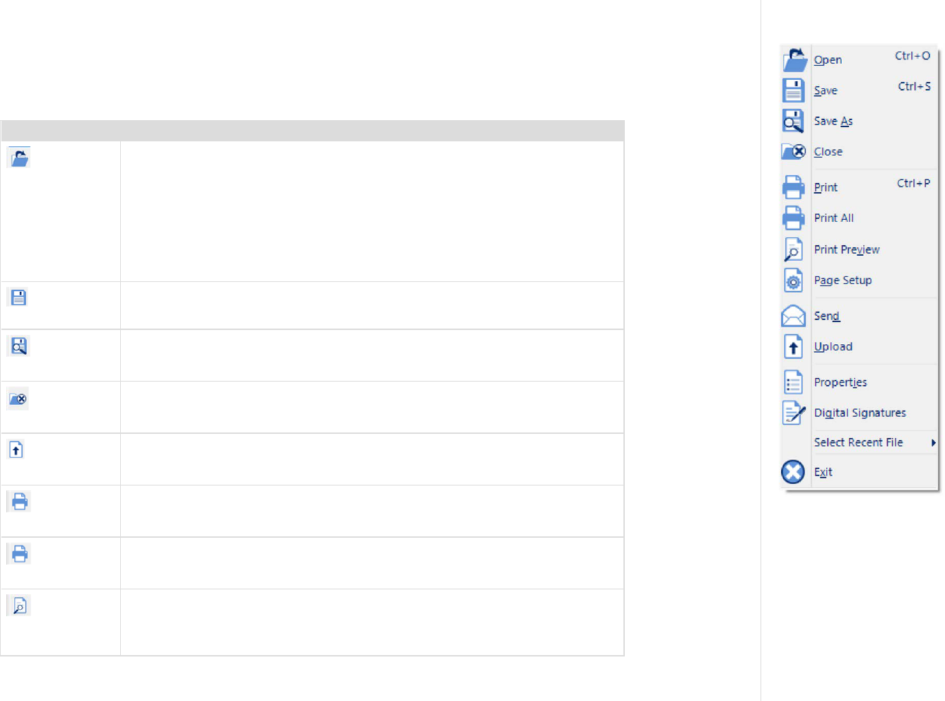
File Menu
Figure 22: File menu
The File menu contains commands that relate to a LogTag
®
file. When clicking on File (or pressing ALT-F on the
keyboard), a menu similar to the one on the right appears.
The following table outlines the commands you can select along with a brief explanation. Some commands do not
appear if no file is open.
Command Explanation
Open...
This will display the Open file dialogue, which will allow you to open files that were
previously saved with any version of LogTag Analyzer, such as *.ltd, *.ltdx or *.sltd
files and multi chart files such as *.multi or *.multix.
Initially, the folder defined in Edit - Options - File and Folder Settings will be
displayed. When you open a file after you browsed to a different location, LogTag
Analyzer will remember this location for the next time you wish to open a file.
If a multi chart file is selected, the LogTag Analyzer software will automatically show
the opened file as a new multi chart (see Multi Charts (Combining Charts into a
Single View) on page111).
Save
This will save any changes you have made to the LogTag file (or multi chart
configuration) to your disk drive.
Save As...
This will display the Save As file dialog, which will allow you to save a copy of the
file currently being displayed in the same or a different folder with the same or a
different file name, in the same or a different file format .
Close
This will close the currently active file. You may be asked to confirm if you wish to
save any changes, such as annotations or zoom settings. If no files are currently
open this command will not be visible.
Upload
This will send an email with the currently active file attached to a list of recipients or
upload the file to a ere-determined FTP site, as detailed in Sharing recorded data
with others on page138.
Print...
This will open a window allowing you to print the currently active window to a
printer. This command is further explained in the section Printing the results on
page132.
Print All...
This will open a window allowing you to print all currently open windows to a
printer. This command is further explained in the section Printing the results on
page132.
Print Preview
This will change the display mode of the software to show you a copy of how a
printout of the currently selected file and window would look like. In "Print Preview"
mode you will not be able to zoom in or out of a chart. Click to exit the "Print
Preview" mode and return to normal display mode.
Table 1: File menu - available commands
Using LogTag Analyzer
LogTag
®
Analyzer User Guide
page 32

Command Explanation
Page Setup...
This will open a window allowing you to view and adjust one or more of your page
settings, like printer margins and page orientation.
Send...
This will help you send, by email, the currently open and selected LogTag
®
file to
another user without the need to exit to your email software or to deal with file
attachments. This command is explained in further detail in the section Sending a
file by email directly from LogTag Analyzer on page138.
Properties...
This will open a window that will display the information about the file that is being
displayed and currently selected. This same window and information will be
displayed if you view the properties of the file from Microsoft Windows Explorer.
Digital Signature...
This will open a window to display a list of digital signatures that have been included
with the file. It also allows you to add and print this list of digital signatures. Further
explanations can be found in the section about Digital signatures on page95.
Select Recent File This sub-menu, when clicked, shows a list of the most recent files you have viewed.
This includes any files that were opened when you donwloaded a logger.
To re-open one of these files, simply click the name of the file. The number of files
included in this list can be adjusted in Edit - Options - File and Folder Settings.
Exit
This command will exit the LogTag Analyzer software. Any files currently open will
be closed automatically. If a user is currently logged on to the User Server, the user
will be automatically logged off.
Using LogTag Analyzer
LogTag
®
Analyzer User Guide
page 33

Edit Menu
Figure 23: LogTag Analyzer Edit menu
The following table outlines the commands you can select along with a brief explanation. Some commands do not
appear if no file is open.
Command Explanation
Copy
Places a copy of the contents of the currently displayed window onto the clipboard,
which can then be pasted into any Windows
®
application. The Copy command
behaves slightly differently for different tabs, please refer to the descriptions
covering individual tabs for further details.
Zoom Out
This will undo the last zoom operation. If the chart is displaying all readings
recorded, this command will not be available.
Real Time
Clicking this menu item will make the time axis represent date and time the data
were recorded. This is useful when you want to inspected at what date and time a
certain event occurred.
Elapsed Time
Clicking this menu item will make the time axis represents the elapsed time since
the recording began. This is useful when you want to inspected how long into a trip a
certain event occurred.
Zoom to Marks
When this command is enabled, the chart is automatically zoomed to show readings
recorded between inspection marks. The section Starting and using the LogTag
®
explains how inspection marks are recorded.
Previous group of
Marks
This command will show the readings recorded between the first inspection mark
shown and the previous inspection mark recorded. This command will only be
available if the "Zoom to Marks" command is enabled and the first reading recorded
is not currently visible.
Next group of
Marks
This command will show the readings recorded between the last inspection mark
shown and the next inspection mark recorded. This command will only be available if
the "Zoom to Marks" command is enabled and the last reading recorded is not
currently visible.
Options...
This will open a window allowing you to customize the software. This command is
further explained in the chapter Customizing the Software on page147.
Table 2: Edit menu - available commands
Using LogTag Analyzer
LogTag
®
Analyzer User Guide
page 34

LogTag
®
Menu
The LogTag menu contains commands for interaction with LogTag
®
products.
Figure 24: LogTag Menu
When you click LogTag (or press ALT-L on the keyboard), a menu similar to the one on the right appears.
The following table outlines the commands you can select along with a brief explanation.
Command Explanation
Configure
This will display a wizard to help you through the necessary steps to configure
LogTag products for their next use. This command is explained in more detail in the
chapter Configuring a LogTag® product for recording (on page48).
Download
This will display a wizard to help you through the necessary steps to retrieve a copy
of the readings stored inside the logger. This command is explained in further detail
in the chapter Results from LogTag® Loggers (on page92).
Hibernate
This will display a wizard to help you through the necessary steps to switch LogTag
products to "Hibernation". This command is explained further in the chapter
Hibernation - Prolonging battery life (on page82).
Quick Re-
configure
With this command you can re-configure a logger with the same settings as for the
previous trip. This command is explained in further detail in the section Quickly re-
configuring a LogTag® logger (on page78)
Profiles
With this command you can configure a logger with a configuration profile previously
created. This command is explained in further detail in the section about
Configuration Profiles (on page84).
Wizard...
This will display a wizard to help you through the necessary steps to retrieve a copy
of the recorded readings stored inside a LogTag device and then prepare it for its next
use. This command is explained in further detail in the chapter Configuring a
LogTag® product for recording (on page48).
Table 3: LogTag menu - available commands
Using LogTag Analyzer
LogTag
®
Analyzer User Guide
page 35

LogTag
®
Online Menu
The LogTag Online menu contains commands for interaction with the LogTag
®
web based storage and analysis
portal, LogTag Online. You can find details about connecting LogTag Analyzer and LogTag Online in the section
about Integrating LogTag Analyzer with LogTag Online. If you want to know more about LogTag Online and its
features please go to https://logtagonline.com/support.
Figure 25: LogTag Online Menu
When you click LogTag Online (or press ALT-O on the keyboard), a menu similar to the one on the right appears.
The following table outlines the commands you can select along with a brief explanation.
Command Explanation
Sign In
This will display a dialogue where you can enter your user name and password for
LogTag Online.
Sign Out
If you are signed into your LogTag Online account, you can sign out if you click this
menu entry.
Create an Account
This will open your default browser and display a web page where you can create a
new a LogTag Online account. For this, you will require internet access and an email
address.
Connection
Wizard
This will open the LogTag
®
Online Connection Wizard, which is used to configure the
settings for WiFi enabled devices such as interfaces (LTI-WIFI and LTI-WM-WIFI)
and real-time loggers (UTRED30-WIFI).
The wizard is a stand-alone Windows app that will be installed together with LogTag
Analyzer.
You can find more information about the functionality of the LogTag
®
Online
Connection Wizard in the wizard's online help. You can also access the Wizard from
the Windows Start menu if LogTag Analyzer is not running,
Current Team
LogTag Online allows you to be a member of multiple teams, however, LogTag
Analyzer can only be connected to one of the teams at any one time. You can choose
which of your teams is connected by selecting its name in this menu entry. LogTag
Analyzer will remember your team setting for the next time it is opened.
Table 4: LogTag Online menu - available commands
Using LogTag Analyzer
LogTag
®
Analyzer User Guide
page 36
Window Menu
Figure 26: Window menu
The Window menu contains commands that relate to the management of windows open in LogTag Analyzer,
which display the contents of a LogTag
®
file.
Commands available in the Window menu:
Command Explanation
New
Window
Opens a new window that contains a copy of the information of the currently selected window. This command is
useful when you need to closely inspect and analyze different sections of the same file.
Close
Closes the currently selected window.
Close All
Closes all open windows.
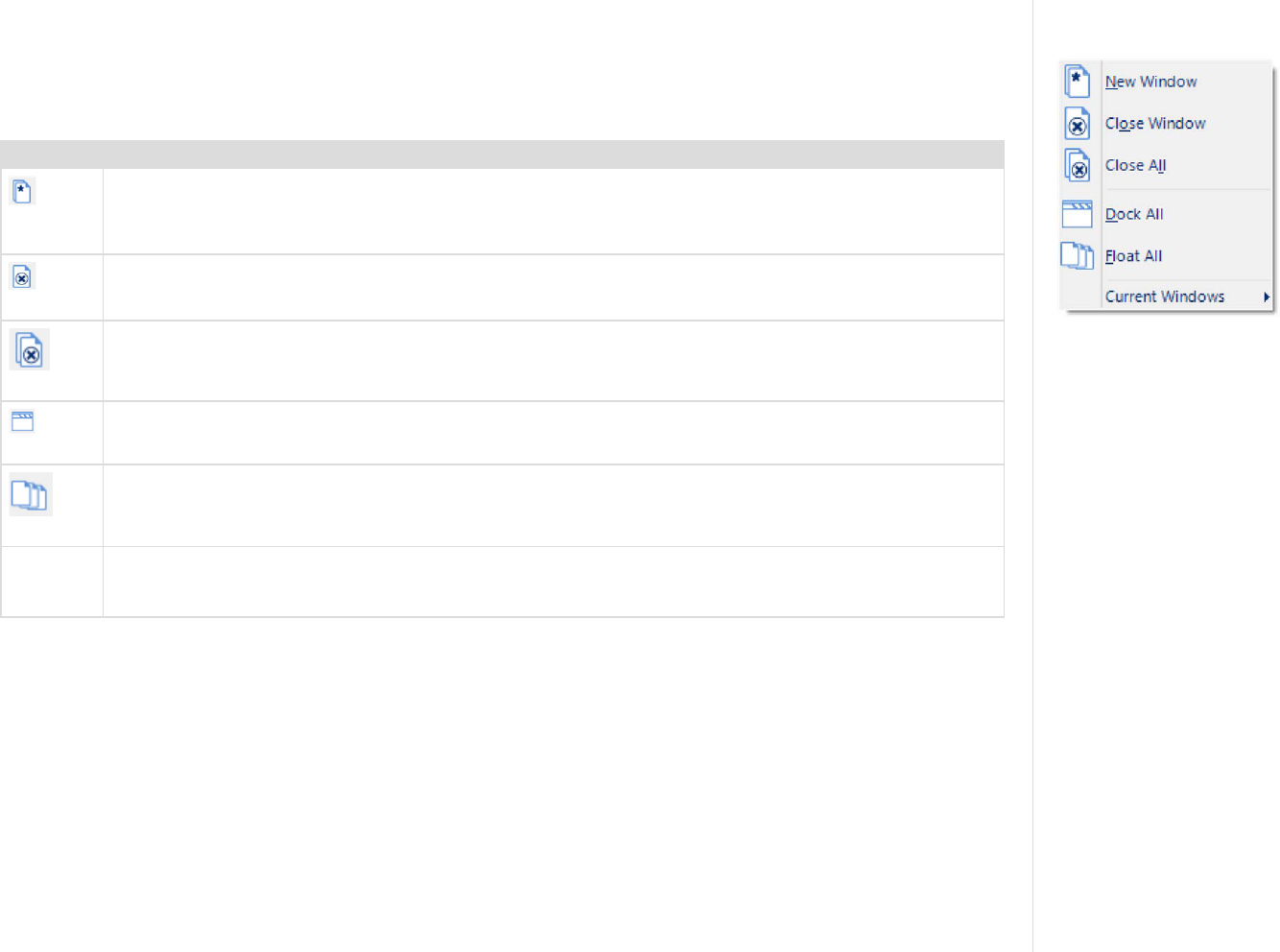
Dock All
Maximizes all windows inside LogTag Analyzer's docking canvas, with a tab for each window.
Float All
Un-docks all windows, so they can be positioned freely around the computer monitor.
Current
Windows
This sub-menu, when clicked, shows a list of the currently open windows. Click on an entry to bring the window
to the front. If you want to change the currently selected window to one of the windows listed, just click/select
the appropriate entry on this list.
Table 5: Window menu - available commands
Using LogTag Analyzer
LogTag
®
Analyzer User Guide
page 37

User Server Menu
Figure 27: User Server menu
The User Server menu contains commands that allow you to log on and off. When clicking on User Server (or
pressing ALT-U on the keyboard), a menu similar to the one one on the right appears.
The following table outlines the commands you can select along with a brief explanation. Some commands do not
appear if no file is open.
Command Explanation
User logon
This allows a user to log on to and use the Analyzer software. When the software is connected to the User
Server software, users must log on to the software prior to being permitted to use the software. Therefore, this
command will only be available if the Analyzer software is connected to the User Server software. If a user is
already logged on to the software, then this command is not visible. The section User Server explains in more
detail how to get the Analyzer software to connect to the User Server software.
User logoff
This allows the currently logged on user to log off the Analyzer software. The username portion of this
command will represent the name of the user currently logged on. If there is no currently logged on user, this
command is not visible.
Change
Password...
This allows the currently logged on user to modify their password that they use to logon to the Analyzer
software. This command will only be available if the Analyzer software is connected to the User Server
software and the User Server administrator has granted the appropriate user permissions.
Settings...
This will open a window allowing you to enter the settings required to connect to or disconnect from LogTag
®
User Server.
Table 6: User Server menu - available commands
Using LogTag Analyzer
LogTag
®
Analyzer User Guide
page 38

Help Menu
Figure 28: Help menu
The Help menu contains commands that provide you with help and assistance when using the LogTag Analyzer
software.
When clicking on Help (or pressing ALT-H on the keyboard), a help menu appears.
The following table outlines the commands you can select along with a brief explanation.
Command Explanation
Help
Topics
Opens a window that contains the online help.
User Guide
Opens the online user guide for viewing. Requires PDF viewing software (such as Acrobat Reader) that can read
version 1.6 compliant PDF files to be installed on the computer.
LogTag
®
Home Page
This will open your default Internet browser software and display the LogTag North America Inc Internet site,
https://logtag.com. This command requires that your computer be currently connected to the Internet to
successfully display the LogTag North America Inc Internet site.
Request
help
This will gather non personal information from your system to include in the email to be sent to software
support at LogTag North America Inc, so that the support team will be informed of the relevant information
about your system in order to provide you with quality and useful assistance. This command is explained in
further detail in the section about Getting more help on page206.
Check
Internet
for update
This is a simple way of checking to see if there is a newer version of this software available for download. This
command is explained in further detail in the section about Upgrading LogTag Analyzer on page24.
About
Analyzer
Display the version information for LogTag Analyzer.
Table 7: Help menu - available commands
Using LogTag Analyzer
LogTag
®
Analyzer User Guide
page 39

Wizard
Invokes the LogTag
®
Wizard. For more details please
refer to Using the LogTag Access Wizard on page78.
Open
Displays the file open window. This allows you to open
previously saved LogTag
®
data files.
Save
Save a copy of the LogTag
®
data to a file on your disk
drive.
Print
Opens the Windows Print dialogue. Please see Printing
the results on page132 for further details.
File properties
Displays file properties about the currently selected file.
File digital signatures
Displays information about any digital signatures
included in the currently selected file. Here you can also
add new digital signatures to files or print copies of the
digital signatures.
Send mail
Creates a new draft email and attaches a copy of the
currently selected file so it can be sent to a recipient of
your choice. Please see Sending a file by email directly
from LogTag Analyzer on page138
Upload
Uploads the file in the currently active window to an FTP
server, or sends it by email. Please see Automatic
emailing and uploading to FTP sites on page139
Table 8: Toolbar icons and their function
Copy
Places a copy of the currently displayed information to
the Windows clipboard, so you can paste it into another
Windows application.
Real Time
When this icon is active, the time axis represents the
elapsed time since the recording began. This is useful
when you want to inspected how long into a trip a certain
event occurred.
Clicking the icon switches to date and time display.
Elapsed Time
When this icon is active, the time axis represents the
date and time. This is useful when you want to inspected
at what date and time a certain event occurred.
Clicking the icon switches to elapsed time display.
Zoom
Controls
Zoom out
Zooms out one level of the chart in the currently active
window. If you are displaying a chart and this function is
not available, then all available data are already being
displayed and you cannot zoom out any further.
Zoom to inspection marks
This zooms the chart so readings are shown between the
oldest reading recorded and the first inspection mark
that exists in the data. If this function is not available
then there are no inspection marks in the data currently
being displayed.
The next two commands will not be available until this
command is activated.
Using LogTag Analyzer
LogTag
®
Analyzer User Guide
page 40
Toolbar commands
The icons on the toolbar give you access to some of the most frequently used commands.
Figure 29: LogTag Analyzer toolbar

Previous inspection mark group
This zooms the chart so readings are shown which were
recorded between the first inspection mark currently
being displayed and the previous inspection mark.
This function is disabled when either the oldest reading
is already being displayed, or the "Zoom to inspection
marks" function has not been activated.
Next inspection mark group
This zooms the chart so readings are shown which were
recorded between the last inspection mark currently
being displayed and the next inspection mark.
This function is disabled when either the newest reading
is already being displayed, or the "Zoom to inspection
marks" function has not been activated.
Average
Combines all open file windows into a single multi chart
window and activates the average tab, or, if already in
multi chart, activates or disables the average tabs. It is
recommended to deactivate this feature when processing
large data sets, as Minimum, Maximum and Average
Charts can require considerable computer resources when
activated.
Multi chart
Displays all currently open charts together in one window
using the same time axis.
Single chart
Opens all charts displayed in a multi chart in their own
individual tabs (the original multi chart remains open).
Options
This will open a window allowing you to customize the
software. You can find a detailed overview over all
settings in the chapter Customizing the Software on
page147.
Log on/Log off
These icons are only displayed if LogTag Analyzer
requires a connection to LogTag
®
User Server software in
order to operate and are used to log on or off. Please see
Connecting to LogTag® User Server on page199 and User
Server on page186.
If you are working with a small computer monitor, not all icons may be visible.
In that case click the down arrow next to the group where the icons are missing,
and you will get an expanded view of the toolbar.
Using LogTag Analyzer
LogTag
®
Analyzer User Guide
page 41

Print preview toolbar
Figure 30: Print preview
The print preview feature -available through the File menu- will
display a view of the data as it would appear printed out. When the
software is displaying a file in print preview mode, an additional
toolbar will appear, similar to the picture one on the right:
Command Explanation
Refresh
This will refresh the displayed data.
Page Navigation
This allows you to navigate between pages. These
controls are disabled if there is only one page to
be displayed.
Print...
This will open the operating system's print
dialogue, allowing you to print a copy of what
you see in the preview. This command is further
explained in the section about Printing the
results on page132.
View Zoom
Here you can select the zoom level with which
the preview window displays the data. This
works much the same as in other windows
applications. It does not influence the printed
data, just how you view them in the preview
window.
Export (Save As)
This function allows you to export the currently
previewed data to one of the listed formats.
These formats are additional to the export
formats listed in Exports and Reports
Table 9: Commands available in the print preview toolbar
Close the preview window with the Close button .
Using LogTag Analyzer
LogTag
®
Analyzer User Guide
page 42

The Status Bar
The status bar is located at the bottom of the LogTag Analyzer
program window.
The status bar shows information about some of the software's active
tasks and settings, and what you can do. You can also select the Time
Zone for the data display.
Using LogTag Analyzer
LogTag
®
Analyzer User Guide
page 43

Dates and Times
Every LogTag
®
product contains a real time clock, which it uses to
determine the recording start time, when to take a reading and when to
stop recording.
Often, the loggers are used for transit monitoring applications, where
goods are transported between different countries, and frequently
different time zones.
Time zone information is included in the loggers' memory, allowing
you to relate shipments from different time zones to each other.
During configuration with a PC, the clock of each logger is set to the
computer's time, and the local time zone of that computer is also
stored in the logger's memory. When the logger is downloaded by the
recipient, LogTag Analyzer is able to use the time zone information
from the logger and the information from the PC used for downloading
to display the data in a variety of different time zones.
Time zone What is displayed
Local PC Time
Zone
All times are displayed in the time zone of the computer
used for viewing the data. This is the most commonly
used option, as it displays the dates and times on screen
in your local time zone.
Note, that this is not the same as the download
time zone, if you were sent a file from a logger
downloaded in a different time zone.
Download Time
Zone
All reading times are displayed relative in the time zone
of the computer used for downloading the data.
Configuration
Time Zone
All reading times are displayed in the time zone of the
computer used for configuring the LogTag
®
product.
You would use this option if you wanted to view the data
in the same way the sender of the logger would see it.
UTC/GMT Time
Zone
All times are displayed in Greenwich Mean Time
(Universal Time Coordinated).
This is the best option when comparing different loggers
from different senders in different time zones.
Table 10: Time zones for data display
The currently used time zone is shown on the status bar:
The default time zone used when first opening a file is set in the
options settings. If you quickly want to switch to another time zone,
without affecting all other charts, you can click on Select Display Time
Zone and choose the desired the time zone from the list.
For additional time zone settings please see Time zones on page183
Upload Status
When either automatic or manual uploading or emailing of files is
enabled, the upload status is displayed at the bottom of the LogTag
Analyzer window in the status bar.
Figure 31: Status bar showing one pending email.
The email counter will decrease as emails are sent. Similarly, the
upload counter will decrease as files have finished uploading.
Using LogTag Analyzer
LogTag
®
Analyzer User Guide
page 44

Color Picker
Figure 32: Basic Color Selection
Figure 33: Advanced Color Selection
In a number of different places throughout the software you can set a color for lines, text or
shade areas. This is done with the help of a color picker, which works similar to selecting a
color in other windows applications such as Microsoft Word.
To change a color for an item, click on its color selection box.
Basic Color Selection
The basic color selection window will appear. If it doesn't, the color for this item cannot be
changed.
The color currently selected for the item is displayed on the right. Click on any of the colors in
the honeycomb to select it. The New color is now shown on the right above the old color, so
you can compare the two.
You can click the color picker and then click on any part of the screen to select that color.
You can enter a hexadecimal RGB color code directly into the field labeled #. This can be
helpful if you have a corporate color scheme you are trying to match.
Advanced Color Selection
You can click on the Advanced tab in the color selection window to bring up a more refined
selection mechanism. Here you have more detailed control over the color, and can also apply
transparency.
Move the slider up or down to select the basic color hue. Then set luminosity (horizontal
movement) and saturation (vertical movement) in the color square and click on the desired
color. Change the alpha value to change transparency (0 = fully transparent, 255 is fully
opaque). The corresponding hexadecimal RGBA color code is displayed in the field labeled #,
where you can also enter a hexadecimal RGBA color code directly. As with the basic window the
color picker is also available.
Using LogTag Analyzer
LogTag
®
Analyzer User Guide
page 45

Initial Set-up
Before you start configuring and downloading loggers we recommend you customize some of
the settings by clicking Options from the Edit menu:
l
Define the display language and temperature units used (General Settings on page149).
l
Choose how time and date are displayed (Date and Time Format on page182).
l
Select how LogTag Analyzer names downloaded files and where these are stored (File and
Folder Settings on page171).
l
Decide which communication ports LogTag Analyzer uses (Communication Ports on
page185).
Sometimes your network administrator will ask you to import settings from a configuration
file. You can read how to do this in the section about Importing and Exporting Option Settings.
Advanced Set-up
Once you are familiar with the basic settings, you can refine your work-flow:
l
Share data with colleagues and project stakeholders by exporting and emailing them (see
Sharing recorded data with others on page138).
l
Enable the report logs, so you can track which loggers you have configured, and what
settings were applied (see Activity Logs on page188).
l
Automate your work-flow with auto-downloading and auto-reconfiguration (see Automation
on page160).
Using LogTag Analyzer
LogTag
®
Analyzer User Guide
page 46

Connecting the Interface
Tip: You can skip this step if you only use USB Loggers.
The standard interface cradles available from LogTag North America Inc connect to a USB
(Universal Serial Bus) port.
Figure 34: Rear of PC with 4 USB ports
These ports are typically located at the rear of workstations, but you can also find ports at the
front, or at the sides if your computer is a laptop. If you are using a USB hub we recommend it
has its own power supply.
LogTag Analyzer can communicate with multiple interface cradles at the same time; you may
connect as many USB interface cradles as the computer supports, although we find that
connecting more than 4 interfaces becomes impractical.
If you install LogTag Analyzer on a computer with no internet connection you must ensure USB
interface cradles are not connected until the software installation is completed, since the
required drivers are installed as part of LogTag Analyzer.
If the software cannot identify a connected USB interface cradle there may have been a
problem during the installation of the driver software. Please refer to the FAQ on the LogTag
North America Inc website for further information.
The LogTag
®
range of USB loggers do not require an interface to communicate with LogTag
Analyzer.
LogTag North America Inc also offers a serial (RS232) port interface. This can be useful for
heavily visualized environments such as Citrix or VMWare, although should no longer be
required with the introduction of the HID-based USB interface. Please contact LogTag for more
information.
Using LogTag Analyzer
LogTag
®
Analyzer User Guide
page 47

Figure 35: Locating loggers and loading initial parameters
Figure 36: LogTag Menu Configure
Some of the LogTag
®
products are delivered to you ready to start, but
most of the time a logger will need to be configured before it can
record temperature or humidity data. During the configuration process
of a logger you define the settings that affect how it records data
during its next trip, such as
l
how and when to start recording, how many readings to record and
at which interval;
l
whether to stop recording after a defined number of readings or to
record continuously;
l
what alerts to process and at which temperature limits;
l
if password protection is required for configuring or downloading;
and
l
what information to show on the logger's display.
To start the configuration process, insert the logger to be configured
into the interface (or a USB socket if you have a USB logger) and click
Configure from the LogTag menu or press F3.
Note: By default the Auto Download feature is enabled, which
means LogTag Analyzer will download any previously recorded
readings. Please see Enable automatic download of readings
from LogTag® devices on page160 for an overview of this
feature.
The LogTag Configure window will be shown, and LogTag Analyzer will
check all connected interface cradles and USB ports for attached
loggers. Every LogTag
®
device found will be listed in the Progress Pane
on the left side, showing the progress of retrieving its configuration
settings.
When all loggers have been found, the configuration settings currently
stored in the logger in the first interface found are shown in the
Parameter Pane on the right. These are either the factory pre-set data,
or the parameters used when this logger was last configured. Model
number and serial number of this logger are shown in the Parameter
Pane.
Using LogTag Analyzer
LogTag
®
Analyzer User Guide
page 48
Configuring a LogTag
®
product for recording

Note: You can attach different logger models at the same
time, however, you can only configure loggers of the same
model at the same time.
Figure 37: Configuration screen for a HAXO-8
In the example shown the first detected logger was a HAXO-8
in the RS232 serial interface. Therefore, the configuration
parameters for this HAXO-8 are shown.
If you wish to configure any of the other loggers found, you
can click on that logger's progress bar, and the parameter
pane will now show the corresponding configuration data for
that logger.
Depending on the logger model, different parameter tabs and
different additional information will be shown.
You can now adjust the configuration parameters for the next trip.
Please note that some loggers are factory preset for specific
applications and will only allow some of the parameters to be
adjusted, but not all of them. Such loggers include, for
example, the WHO PQS listed vaxtag® or USRID-16W models,
which have fixed log interval and alarm settings.
Click the model name hyperlink, and your default web browser will
open, showing the user guide for this model. Here, you can get
additional information about specific configuration parameters for
your model, and how to operate it. For this feature to work, your PC
needs to be connected to the internet.
For some models, additional information is available, such as the
ability to support Smart Probes or being able to print calibration
certificates for the logger. Click the question mark symbol ( ) next to
the feature to get additional information from our online knowledge
base.
When you have entered or adjusted the settings as desired, click
Configure to upload these new configuration data to the device.
The logger is now ready to be started.
Using LogTag Analyzer
LogTag
®
Analyzer User Guide
page 49

Command Buttons
In addition to the Configure button, following other actions are available in this screen:
l
Rescan
Scans all connected interfaces and USB ports again. Click this button if you have inserted
additional USB loggers you wish to configure, or not all connected USB loggers appear in the
Progress Pane.
l
Save Profile
You can save the parameters as entered to a Configuration Profile. Please see Configuration
Profiles on page84.
l
Cancel
You can abort the configuration process by clicking this button.
l
Help
Clicking this button brings up a browser window, showing help for this topic.
l
Repeat Configure
This button is available only after one or more loggers have been configured. Clicking this
button will scan all interfaces and USB ports for loggers again, and upload the entered
configuration data to each eligible logger.
l
Restart
Click to start the configuration process from the beginning.
l
Certificate of Calibration
Click to view the logger's factory Calibration Certificate.
l
Recover logger
Click if a logger is to be recovered from a failed upgrade. Please see Recovering from a failed
firmware update for further details.
Depending on the possible actions, not all buttons may be shown. If a button is not shown, its
corresponding action cannot be performed.
Using LogTag Analyzer
LogTag
®
Analyzer User Guide
page 50

Progress Pane
Figure 38: Progress Pane Indicator
Each logger found will be listed in the Progress pane. It is represented by its model number,
serial number and operational status, shown via different icons, which change once a logger is
configured:
When you see this icon displayed in the progress bar, the parameters entered for configuration
will be applied to this logger when clicking Configure
When you see this icon, the logger will not be configured when you click Configure, since the
model is different from the one for which you have entered configuration parameters.
A logger showing this icon cannot be configured, as there are no trips remaining. This applies
to single use loggers or loggers that have a locked configuration. You will see this for example
on SRIC-4 or USRIC-8 loggers when you attempt to configure them for a second trip.
This logger has a low battery. Some models cannot be configured when they have a low battery.
This icon is displayed after the logger has been successfully configured. This logger can now be
started, or will start automatically, depending on the chosen start options.
The progress bar will also show the word Configured
This icon is displayed after an unsuccessful attempt to configure the logger. Further error
messages will be displayed to indicate why the logger was not configured.
This icon is displayed after the logger has been successfully configured, but the logger has some
advanced features that the software could not set. This typically happens if you try to configure
older and newer loggers together. When you hover the mouse over this icon you can see which
features were not set.
While the software is sending the new configuration data to each logger, progress bars in the
Progress Pane will identify the loggers that are being configured.
Figure 39: Logger configured
Once finished the progress bar shows Configured.
If you use Repeat Configure to configure another logger, you may update its configuration
without having first saved previously recorded data.
As soon as a logger is configured, previous data can no longer be downloaded. Please
ensure you have downloaded the readings before completing the configuring process to
avoid data loss.
Using LogTag Analyzer
LogTag
®
Analyzer User Guide
page 51

If additional loggers of the same model have been located, these loggers will also be configured
with the new data.
If you enable Retain Description/Password, existing descriptions and passwords for each logger
will be retained, instead of using the details from the configuration parameters entered. Note
that you will still need to provide a password for loggers that have an active configuration
password protection. On loggers with WiFi capability the existing network password will also be
retained.
The next sections describe each configurable option; please note, however, that not every
option is present for each of the LogTag
®
models.
Instead of entering every configuration detail repeatedly, you can configure loggers using pre-
configured profiles, or prepare them for a new trip with the same configuration data as used
for just completed trip by using the quick re-configure function. For more details on these
options please see Configuration Profiles on page84 and Quickly re-configuring a LogTag®
logger on page78.
Working with more than one logger
At some stage you may need to perform a similar task on multiple LogTag
®
devices, whether it
is retrieving readings or preparing them for a new trip. LogTag Analyzer has been designed to
make working with multiple LogTag
®
units easy.
1. You can connect multiple interfaces to your PC, so more than one logger can be
configured or downloaded at the same time.
2. Use the Auto-download feature. To retrieve a copy of the recorded readings from multiple
LogTag
®
products, simply insert each one into the Interface cradle (or plug them into the
USB port). The software will automatically retrieve the recorded data, save it to disk and
then display the information for you (Automation on page160). You can repeat this for
each product without needing to interact with the software.
3. Use the Repeat feature in the configuration window without having to re-enter the same
parameters more than once, even with different descriptions or passwords.
4. Use a pre-configured Profile (Configuration Profiles on page84) or the Quick Reconfigure
feature (Quickly re-configuring a LogTag® logger on page78)
Using LogTag Analyzer
LogTag
®
Analyzer User Guide
page 52

User Related Configuration Parameters
User related configuration parameters are entered at the top of the
Parameter Pane:
Description
(optional)
This can be used for identification of the load in transit to be
monitored, or simply an identifier that describes the purpose of the
monitoring. Bill of Loading information, Shipper, commodity, contact
name and other relevant information can be placed here. For loggers
with two recording channels, such as the new UTRED30-16 and
UTRED30-WiFi, a separate description field will be shown for each
channel. This will make it easier to identify in the files which probe is
monitoring what environment.
Each description can be up to 38 characters long (36 for loggers with a
display) and can contain a mix of letters, numbers and special
characters. The selected input language of the computer's operating
system determines which special characters can be selected.
If a user decides to make use of special characters, extra information
about the language used is stored inside the logger. Users will then
need LogTag Analyzer 2.3 Release 7 or later so the User ID is correctly
displayed.
If you use the special character sets for languages such as Greek or
Chinese, the maximum number of characters that can be used will be
reduced due to the increased memory required to store the characters.
Please Appendix on page195 for a more detailed explanation.
To view the PDF file generated by a USB logger, the fonts used
must be present on the receiver's computer. PDF Reader
software typically only installs a small number of fonts, none
of which support an extended character set. Therefore, you can
only use ASCII characters in the User ID field when configuring
a USB logger.
Configure requires a password
If you select this option, any user wishing to configure the logger in the
future must provide this password. A new entry field appears, where
you can specify which password you wish to use.
Passwords are case sensitive ("Bob" and "bob" for example are
different passwords).
If you enter a new password, or change an existing password, you will
need to verify the password when you click Configure.
If you use special character sets for languages such as Greek or
Chinese, the maximum number of characters that can be used will be
reduced due to the increased memory required to store the characters.
Please see the Appendix on page195 for a more detailed explanation.
Due to the restrictions in the Description field you can only use ASCII
characters in the password field when configuring a USB logger.
Download requires a password
If you select this option, the recorded data from the logger can only be
downloaded after entering the correct password.
Only one password can be provided for each LogTag
®
unit. The same
password applies to the Configure and Download actions.
Battery condition
If the battery in the logger reports 'low', it should no longer be used.
The software will display a warning in the top right corner.
Some LogTag
®
models display the remaining percentage in this screen
once it falls below half capacity. Some models cannot be configured any
longer once their battery capacity falls below a pre-determined
threshold.
Remaining Starts
If the logger you are configuring has a limited number of starts, this
will be indicated here.
Using LogTag Analyzer
LogTag
®
Analyzer User Guide
page 53
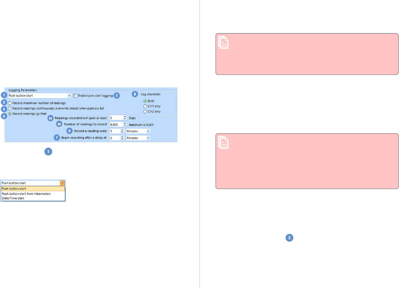
Upgrade logger
Some loggers can be upgraded, to enable new features that were not
previously available. One example is permitting the "Password on
download" option for some logger models. Such an upgrade can be
applied by enabling Upgrade logger. Please note, however, that older
software will most likely no longer be able to communicate with the
logger once it has been upgraded.
Logging Related Configuration Parameters
Logging related configuration parameters are entered in the middle
section of the Parameter Pane:
Start method
(mandatory)
Click the field to set how and when a logger will start recording its next
trip.
l
Push button start
When the 'Push button start' option is selected, the logger will start
recording when the START button has been pressed and held until
both the OK and Alert lights alternately flash on and off.
l
Date/Time start
When the 'Date/Time start' option is selected, the logger will
automatically start recording at a specified date and time. Two
additional entry fields will appear, one for selecting the date, the
other for the time. Enable pre-start logging and Begin recording
after... (delayed start) options are not available with a date/time
start.
Pressing the START button prior to the start date/time will have no
effect.
Note: When using the Date/Time start option, the start time
must be at least two minutes into the future. This delay
allows you to complete the remaining configuration options
and gives the software enough time to upload the
configuration to the device before it is due to start.
l
Push button start from hibernation
When the 'Push button start from hibernation' option is selected,
the logger will start as if programmed for 'Push button start'. The
difference is that once the configuration is successfully uploaded to
the logger it will be placed into hibernation. When the START/Mark
button is pressed and held, the logger will wake from hibernation
and start recording with the parameters as configured.
Note: When using this start option, the real time clock
inside the logger is suspended until logging starts. When
downloading at the end of the trip, the reading times are
back-calculated based on the time of the computer on
which the unit is downloaded. It is therefore necessary that
computer is set to the correct time, so the downloaded data
have the correct date/time.
Please see Hibernation - Prolonging battery life on page82 for more
information.
Not every LogTag
®
model can support every start mechanism. If a start
option is not listed during the configuration process, this option is not
available for this model.
Enable pre-start logging
(optional)
When you enable Pre-start logging, the logger starts taking readings as
soon as the configuration data have been uploaded. If you forget to
press the START button, the data for the trip will still be available. This
Using LogTag Analyzer
LogTag
®
Analyzer User Guide
page 54

ensures no critical data are lost. This option is further explained in the
section Pre-start data collection on page80.
Pre-start readings will not be recorded if the start method is
'Date/time' or 'Push button start from hibernation'.
Record maximum number of readings
(Profile only)
When you select this option in a profile, the logger fills the complete
memory with readings, and then stops. This feature is useful for
profiles that can be applied to products with different memory sizes,
for example the USRIC-8 and USRIC-16 models.
Record readings continuously, overwrite oldest when
memory full
(mandatory
1
)
When you select this option, the logger initially fills the complete
memory with readings, then overwrites the oldest data when the
memory is full. For a more detailed explanation see Continuous
operation on page79
Record readings so that:
(mandatory)
If this is selected, the logger stops logging taking after a pre-
determined number of readings. The following two fields determine the
time these recordings will cover.
Please note that some LogTag
®
logger models can be stopped
manually, so there may be fewer than expected readings.
1
You must select either continuous recording, or recording for a defined time span
Readings recorded will span at least X days
(mandatory
2
)
If you know how many days of data you want to record, enter this
number here. The shortest possible recording interval that covers this
period will be automatically calculated, based on how frequently the
logger takes a reading.
Number of readings to record (maximum is Y)
(mandatory)
This field will display the calculated number of readings if you select a
time period and an interval. Alternatively, you can select the number of
readings desired, and the time period will be calculated based on the
interval. Y represents the maximum number of readings the product
can store, however with a selected interval and a selected time span,
you may not need to use all of the available memory.
Record a reading every X
(mandatory)
This determines how frequently the LogTag
®
records and stores
humidity or temperature values. Select seconds, minutes or hours, then
change the number to suit
3
, either by clicking the up or down arrows,
or by typing a number value directly.
If you want to use a log interval such as 1 minute 30 seconds,
enter the number in full seconds.
Begin recording after a delay of X
(optional)
Enter the time that passes after a user has pressed the START button
on the logger until the start of the recording. Select minutes or hours
3
,
then change the number to suit, either by clicking the up or down
arrows, or by typing a number value directly. This feature is useful for
example, when the logger could falsely trigger an alert because the
2
The entries are interdependent, changing log interval may change the number of days the logger can
take readings for
3
Different models support different minimum/maximum log intervals and start delays. Please refer to
the individual models' data sheets for more information.
Using LogTag Analyzer
LogTag
®
Analyzer User Guide
page 55

environmental conditions to be monitored are quite different to the
environment in which it is started.
If pre-start logging is enabled, the LogTag
®
logger will still
continue to record pre-start readings during this delay period.
Log Channels
(mandatory, only for Dual-Channel loggers)
This option is displayed only for Dual-Channel loggers, such as the new
UTRED30-16. Here, you can select which of the channels you wish to
record. When you select CH1 only, the logger records temperature
values only for the probe connected to the socket marked CH1, while
CH2 only records only the probe plugged into CH2. Both means that
both channels will be recorded. This is also the ex -factory default.
Note that the number of activated channels has no influence
on the number of readings you can record. This will remain the
same, no matter how many channels are activated for
recording.
You will not be able to retrieve any readings from a channel
that is de-activated. If you select CH1 only, and plug the probe
into CH2, no readings will be recorded if no probe is plugged
into CH1. We therefore recommend to leave this settings on
Both, unless you have specific reasons to de-activate one
channel.
Using LogTag Analyzer
LogTag
®
Analyzer User Guide
page 56

Configuring Alarms
All LogTag
®
loggers can display a visual alert if one or more configured
alarm trigger conditions have been met. Some models also have the
option for the alarm to be audible (see Audible Alarm as described on
page60). Each alarm trigger condition consists of a threshold value, an
activation type (which can be instant, consecutive or accumulative
4
)
and a delay time, if it is not an instant alarm.
If an alarm trigger condition requires readings to exceed an upper
threshold temperature it is called an upper alarm. If an alarm trigger
condition requires readings to go below lower thresholds it is called a
lower alarm.
The threshold parameters are shown in LogTag Analyzer when the
logger's readings are downloaded and displayed.
Alarm related configuration parameters are entered in the bottom
section of the Parameter Pane:
4
l
Instant = one temperature reading is above (below) the threshold
l
Consecutive = temperature readings are above (below) the threshold for the time defined in the
activation delay without interruption
l
Accumulative = temperature readings are above (below) the threshold for the total time defined in
the activation delay time, but may not necessarily be sequential.
You will find one or more tabs, depending on the logger model you
wish to configure. Click the tab's label to show the parameters for that
tab.
HAXO-8, HASO-8 and UHADO-16 loggers show two tabs, one for
temperature alert conditions, one for humidity. Dual-channel loggers
also display two tabs, so you can configure different alarm settings for
each channel.
Note that some values apply to both tabs simultaneously, such as the
OK indicator field.
Standard Alert Related Configuration Parameters
Enable the OK (Green) indicator
This determines whether or not the green LED should blink while the
LogTag
®
is recording. This is not available for display products.
Enable the Alert (Red) indicator when...
This defines whether or not the red light should activate when an alert
condition has been detected. An alert occurs when one or more of the
conditions described below have been met. When an alert condition has
occurred, this indicator will flash at a regular interval.
Readings below X or above Y (inclusive)
You can set the upper and lower threshold limits by typing the
appropriate information directly in the boxes, or by moving the value
slider, or a combination of both. If readings stay inside the range
specified by X and Y the alert indicator will not activate. If a reading of
X and below, or Y and above is recorded, the alert indicator may light
up, depending on the alert conditions. Charts will display alert readings
according the settings made in the Charts section of the Options
Screen.
The values entered in these boxes are included in the alert range. In
the example later in this section 7 consecutive readings of 45 °C will
trigger an alert, whereas 7 consecutive readings of 44.9 °C will not
trigger an alert. Please set your alert values with this in mind.
Some logger models allow you to enable upper and lower alerts
independent of each other; this is useful in situations where one of the
Using LogTag Analyzer
LogTag
®
Analyzer User Guide
page 57

alert thresholds is irrelevant to your recordings and, if left activated,
may falsely activate the alert LED. In this case there will be one check
box for each alert.
After X consecutive alert readings (W minutes)
Tick this box and enter a number into the adjacent field if you want to
trigger an alert condition once X number of consecutive alert readings
are recorded. Note that the number of minutes shown will depend on
the number of alert readings you enter into the box AND the recording
interval already specified. For example, if X is 3 and two readings are
above the upper threshold limit, but the subsequent reading is below
the upper threshold limit and still above the lower threshold limit then
the alert indicator will not activate. Maximum value is 256, minimum is
2.
After X alert readings have occurred (W minutes)
Tick this box and enter a number into the adjacent field if you want to
trigger an alert condition once a total number of alert readings have
been recorded, regardless of whether they are consecutive or not.
Maximum value is 256, minimum is 2.
You can increase or decrease the values with the arrows next to the
fields. Please note these are linked and certain combinations may not
be allowed.
Leave alert indicator enabled even if readings return within alert range
If this option is enabled, the alert indicator will remain active, even if
the current reading does not meet the alert conditions specified by the
previous controls.
If this option is disabled, the alert indicator will remain active only if
the current reading meets the alert conditions specified by the previous
controls.
Please note, however, that this setting is only applicable if an
immediate alert is configured; if consecutive or accumulative alert
settings are configured this box has no effect, and the alert indicator
will always remain visible once an alert has occurred.
Clear and reset alert when START MARK button pressed
If this feature is enabled, any user can turn off an active alert by
pressing the START/MARK button directly on the device. This will also
reset the internal alert counters as if no alert condition had occurred at
all while the LogTag
®
was recording.
Should the logger subsequently detect a further alert condition, the
alert will activate again.
Once the LogTag
®
has finished recording, pressing the START/MARK
button will not clear and reset any active alert.
If the LogTag
®
being configured does not support this feature, it will be
disabled and its setting cannot be changed.
Example:
You wish to configure a LogTag
®
so alert conditions are indicated if 5
continuous readings are out-of-range or 7 total readings are out-of-
range. Alert parameters should be set as follows:
This table shows how different conditions would result in the Alert
Indicator flashing or not:
What the LogTag
®
recorded
What the LogTag
®
indicated
2 readings out-of-range, return
to normal, 2 readings out-of-
range, return to normal, 2
readings out-of-range, return to
normal
Neither alert condition is met.
The maximum number of consecutive out-
of-spec readings is only 2 (5 required.)
The total out-of-range events equals 2 + 2
+ 2 = 6. The alert condition is 7 total, so no
alert is triggered.
No Flashing Red Alert Indicator
Table 11: Alert examples
Using LogTag Analyzer
LogTag
®
Analyzer User Guide
page 58

What the LogTag
®
recorded
What the LogTag
®
indicated
4 readings out-of-range, return
to normal, 4 readings out-of-
range
The first alert condition is not met, as the
maximum number of consecutive alert
condition readings is only 4 (5 required.)
The second alert condition however IS met
since the total alert condition readings
equals 4 + 4 = 8. The alert condition is 7
total. so the alert IS triggered.
Flashing Red Alert Indicator
4 readings out-of-range, return
to normal, 2 readings out-of-
range
Neither alert condition is met.
The maximum number of consecutive alert
condition readings is only 4 (5 required.)
The total number of alert condition
readings equals 4 + 2 = 6. The alert
condition is 7 total, so no alert is triggered.
No Flashing Red Alert Indicator
6 readings out-of-range, return
to normal
The second alert condition is not met, as
the total out-of-range events equals 6 (7
required.)
The maximum number of consecutive alert
condition readings however is 6, the alert
condition is 5 consecutive readings, so the
alert IS triggered.
Flashing Red Alert Indicator
Please note following special conditions:
1. If you wish an alert to be indicated on the first reading that is
recorded out-of-spec, place a tick in the box next to "Enable the
Alert (Red) indicator when" and remove the ticks in both boxes
next to the "After X consecutive alert readings" and "After X
alert readings have occurred".
2. You cannot enter a number into the "After X consecutive alert
readings" field which is larger than the number in "After X alert
readings have occurred", since the latter alert condition would
always be met first.
3. Similarly, you cannot enter a number into the "After X alert
readings have occurred" field which is smaller than the number
in "After X consecutive alert readings". The software will adjust
field values as appropriate.
Advanced Alert Settings
Some loggers support more detailed alert settings than described
before. If LogTag Analyzer encounters one of these loggers, additional
tabs are visible in the Parameter Pane:
You can access the extra tab by clicking on the tab's label.
In the advanced settings the red alert indicator can now be configured
independently for upper and lower alert values.
Readings above X
Readings below Y
(inclusive)
In addition to entering the threshold levels, tick the boxes next to
"Readings above" or "Readings below" to enable the alert conditions
for only the upper or only the lower threshold settings, or for both. If
both boxes are ticked, the behavior is the same as for the standard
alert settings. The charts will display alert readings according to the
settings made in the Charts section of the 'Options' Screen.
After X consecutive alert readings (W minutes)
Readings above
Readings below
Tick the boxes next to "Readings above" or "Readings below" to
establish whether only readings above and including the upper
threshold or only readings below and including the lower threshold
should count towards the consecutive alert readings. If both boxes are
ticked, the behavior is the same as for the standard alert settings. If
the Alert Indicator is disabled for either the upper or the lower alert,
the respective box for the consecutive alert is grayed out and cannot be
ticked.
After X alert readings have occurred (W minutes)
Readings above
Readings below
Tick the boxes next to "Readings above" or "Readings below" to
establish whether only readings above and including the upper
threshold or only readings below and including the lower threshold
should count towards the total number of alert readings. If both boxes
Using LogTag Analyzer
LogTag
®
Analyzer User Guide
page 59

are ticked, the behavior is the same as for the standard alert settings. If
the Alert Indicator is disabled for either the upper or the lower alert,
the respective box for the alert total is grayed out and cannot be ticked.
The advanced settings tab is displayed automatically if an advanced
configuration is already found in the logger to be configured. If you do
not wish to use the advanced settings, click the Temperature Alarm
Settings tab.
Example:
You wish to configure a LogTag
®
so an alert is displayed if 5 continuous
readings are out-of-range or 7 total readings are out-of-range, but
only if the temperature goes to 20 °C and above. You wish to see in
LogTag Analyzer if the product has gone to 0 °C and below, but you do
not wish to trigger an alert for this condition. Alert parameters should
be set as follows:
Figure 41: Advanced Alert Settings - Sample settings
The following table shows how different conditions would result in the
Alert Indicator flashing or not:
What the LogTag
®
recorded
What the LogTag
®
indicated
2 readings of 20 °C or above,
return to normal, 8 readings at
0 °C or below, return to normal,
4 readings of 20 °C or above,
return to normal
Neither alert condition is met.
The maximum number of consecutive out-
of-spec readings is only 2 (5 required, the 8
readings below 0 °C do not count towards
alert readings).
The total out-of-range events equals 2 + 4
= 6. The alert condition is 7 total, so no
alert is triggered, as again the 8 readings
below 0 °C do not count towards alert
readings.
No Flashing Red Alert Indicator
Table 12: Advanced alert examples
What the LogTag
®
recorded
What the LogTag
®
indicated
4 readings of 20 °C or above,
return to normal, 4 readings of
20 °C or above
The first alert condition is not met, as the
maximum number of consecutive out-of-
spec readings is only 4 (5 required.)
The second alert condition however IS met
since the total out-of-range events equals
4 + 4 = 8. The alert condition is 7 total. so
the alert IS triggered.
Flashing Red Alert Indicator
Separate alert conditions are useful if you expect the monitored product
to encounter temperatures lower than the lowest possible alert
temperature. In this case a flashing alert indicator may not necessarily
indicate an unfavorable condition was encountered. In programs where
such conditions are monitored the lower alert should be turned off.
Audible Alarm
This option is available in TRED30-16R, UHADO-16, UTRED30-16 and
UTRED30-WIFI loggers and can be found in the Advanced Settings or
the Alarm Settings tab. When you enable this option, the logger will
sound an audible alarm when an alarm is triggered. Please refer to the
Product User Guide or Data Sheet of your specific model to establish if
it has a beeper fitted.
Please note, that continual activation of the audible alarm will
reduce the working life of the battery. When an alarm event is
triggered, the alarm should be cleared as soon as possible.
Please refer to the respective Product User Guides for more
information.
Display Logger Advanced Settings
The Alarm settings in loggers with a display (TRID30, TRED30, TRED30-
16R, TREL30-16, UHADO-16, UTRID-16, UTRED-16, UTREL-16, USRID-
16, UTRED30-WIFI, UTREL30-WIFI, UTREL30-16 and UTRED30-16
loggers) are similar to the Advanced Alert Settings on the previous page
or the USB Logger File settings on page66, hence they are not
explained again here.
The loggers do, however, have an additional configuration tab.
Using LogTag Analyzer
LogTag
®
Analyzer User Guide
page 60

When you select this tab, you can access the settings specific to the
display:
Figure 42: Advanced alert options for display loggers
Clear and reset alarm when STOP/CLEAR button pressed
If this option is enabled, any user can turn off an active alarm directly
on the device by pressing the STOP/Clear button. This will turn off the
alarm symbol and reset the internal counters as if no alarm had
occurred while the logger was recording. When the logger subsequently
registers a further alarm condition, the alarm will activate again. Once
the logger has finished recording, pressing the STOP/Clear button will
not clear and reset any active alarm.
An alarm will always be registered in the day summary and
cannot be cleared, regardless of whether the alarm symbol was
cleared or not.
Alarm remains on even if readings return to non-violation
range
If this option is enabled then the alarm symbol will stay on, even if the
current reading does not meet the alarm conditions specified by the
previous controls.
If this option is disabled, the alarm symbol will only stay on if the
current reading meets the alarm conditions specified by the previous
controls.
Please note: Unlike for units without a display these settings
also apply if consecutive or accumulative alert settings are
configured. If the Alarm conditions are no longer met, all
counters are re-set and an alarm is triggered when the alarm
condition is met again. In any case, an alarm will be registered
in the day summary, regardless whether conditions re-set or
not.
Pause alarm/statistics processing for X readings
If this option is enabled, pressing either button on the device while
recording excludes the next reading from the alarm and statistics
calculations; PAUSED will now be shown on the display. This allows the
user to review the statistics or clear an alarm without causing an
invalid reading, alarm or statistic.
Switch off display after 30 seconds
If this option is enabled, the display will turn off after 30 seconds to
save battery power.
Show total summary days collected
If this option is enabled, the display shows the number of days for
which statistics have already been collected.
Please refer to the LogTag
®
Product Specification & User Guide
documents for TRID30,TRED30 and TRED30-16R loggers on the LogTag
North America Inc website at https://logtagrecorders.com/product-
range/ for a detailed description of the functionality of these products.
Note: When referring to TRID30 and TRED30 products, versions
with both the fixed (F-suffix) and replaceable (R-suffix)
battery are included, unless a suffix is specifically mentioned.
For more information please refer to the UTRID-16 PDF Recorder User
Guide, available from the LogTag North America Inc website.
Using LogTag Analyzer
LogTag
®
Analyzer User Guide
page 61

Show user resettable Min/Max (if supported)
This option only applies to newer TREL30-16 and TRED30-16R models.
These devices can display trip min/max settings in addition to the daily
min/max settings. If you enable this setting, these min/max settings
will be displayed when you review the day statistics. The min/max
values can be reset any time while the unit is logging. For more
information please refer to the Product User Guides for the relevant
products.
Allow logging stop with STOP button
If this option is enabled, the logger can be stopped by pressing the
STOP button. It will no longer take any readings, however, you can still
review the day statistics and download the logged results to a PC with
LogTag Analyzer.
Allow reset of logger with START button
If this option is enabled, TRID30, TRED30 and TRED30-16R loggers can
be reset to the same conditions as if they had been freshly configured
by LogTag Analyzer. You can then start another trip by simply pressing
the START button.
When this option is enabled, anyone with access to the
logger can erase all recorded readings and statistics without
saving the data to a PC first. Please use this option with
caution!
A warning box will be displayed to remind you this is enabled and can
result in loss of data.
Enable Quick start/stop if available
This option only applies to TRED30-16R models. If enabled, starting
and stopping a TRED30-16R is faster than that of TRID30 and TRED30.
Instead of holding the start button for 6 seconds (TRID30 and TRED30),
you will only need to press the button for approx. 1 second until the
unit starts or stops. For more detailed information please refer to the
TRED30-16R User Guide, available on the LogTag North America Inc
website at https://logtagrecorders.com/product-range/.
If disabled, the standard start/stop method (6-second button press) is
used.
Show alarm screens during review
(not shown in sample screen)
This option only applies to the UTRID-16. If selected, up to 6 additional
screens are shown when reviewing the data on the display. These
screens show the temperature alarm threshold, and the time above or
below that threshold. If the box is cleared, only the minimum and
maximum screens are shown.
For UHADO-16, UTRED30-16 and UTRED30-WIFI models trip min/max
settings are permanently being shown on the display. If you enable this
setting, a user may reset the min/max values any time while the unit is
logging.
Using LogTag Analyzer
LogTag
®
Analyzer User Guide
page 62

Additional Features for TRED30-16R and TRED30-16CP models
These models show a further tab, where you can enable additional features for this product:
Figure 43: Inspection alarms and fridge/freezer symbols
Inspection Reminder Alarm
When enabled, this alarm triggers when the logger's REVIEW/Mark button was not pressed
between midnight and the time entered, on the selected days. Once triggered, the buzzer will
sound and the time digits will blink until the alarm is cleared by pressing REVIEW/Mark.
If the REVIEW/Mark button was pressed, no alarm will occur for that day.
In the screenshot above, the alarm would be activated if the REVIEW/Mark button has not been
pressed by 9:00am on weekdays. The alarm would not trigger on weekends as it has not been
enabled in the configuration.
If the feature is disabled, an Inspection Reminder Alarm will not trigger.
The feature is also available in the advanced options for a configuration profile and is carried
forward during quick-reconfigure. If a profile, that has the Inspection Reminder Alarm enabled,
is used to configure a TRED30 that does not support this feature, you will see the familiar
warning triangle, reminding you that not all loggers will have been configured with this feature
(see the table of icons on page51).
Fridge/Freezer Indicator
On the display you can show the number of days for which statistical data are stored in
memory. For newer TRED30 models you can select if you wish to show this number, or instead
a symbol, indicating if the logger should be placed in a fridge ( ) or a freezer ( ).
To enable this feature, select Show additional display text and select one of the three options.
Additional Features for TRED30-16R and TRED30-16CP models
LogTag
®
Analyzer User Guide
page 63

Simply selecting the display of the fridge or freezer symbol does not change any
temperature alarm levels. Please make sure you have selected appropriate temperature
alarm trigger conditions that correspond to the symbol you have selected to avoid
incorrectly placed loggers.
If you disable this feature, no text will be shown on the recording display.
The feature is available in the advanced options for a TRED30 configuration profile, and is also
carried forward when using the quick-reconfigure function. If a profile, that has the fridge or
freezer symbols enabled, is used to configure a TRED30-16R that does not support this feature,
you will see the familiar warning triangle, reminding you that not all loggers will have been
configured with all features enabled. Enabling this feature and selecting Show total summary
days collected will also work on earlier units.
For more information about these features and screen samples please refer to the
TRED30-16R Product User Guide.
You will require LogTag
®
Analyzer version 2.9 or later to configure and download
loggers with these features.
Enabling Smart Probes
This section of the window will only be shown for the new TRED30-16CP loggers, which
support the new CP110 Smart Probes. Unlike the UTRED30-WiFi and UTRED30-16 models, you
must select which probe you will use with the logger during the configuration process.
If your probe features a small case as shown below, it is one of the new Smart Probes. You
must enable the Smart Probe feature so your logger records temperature data.
Figure 44: CP110 Smart Probe for TRED30-16CP Loggers
If your probe does not have such a case, it is a standard (analogue) probe, and you must enable
the standard probe.
Additional Features for TRED30-16R and TRED30-16CP models
LogTag
®
Analyzer User Guide
page 64

If you enable the feature without using a Smart Probe, or vice versa, you will not record
the correct temperature!
How is my calibration affected when swapping probes?
Probes of the same type can be swapped during recording, however, you will need to observe
some rules if you wish to maintain a calibrated system:
l
You can swap one Smart Probe with a different one without re-configuring the unit. If the
new probe is calibrated, the complete logger and probe system will remain calibrated.
l
You can also swap one standard probe with a different standard probe, however, to maintain
system calibration the logger and probe will have to be re-calibrated as a system.
l
If you swap a Smart Probe with a standard probe you will need to re-configure the logger,
select "Standard Probe" during configuration and also re-calibrate the system if required.
l
If you swap a standard probe with a Smart Probe you will need to re-configure the logger
and select "Smart Probe" during configuration. If the probe itself is calibrated, re-
calibration of the system is not required.
Additional Features for TRED30-16R and TRED30-16CP models
LogTag
®
Analyzer User Guide
page 65
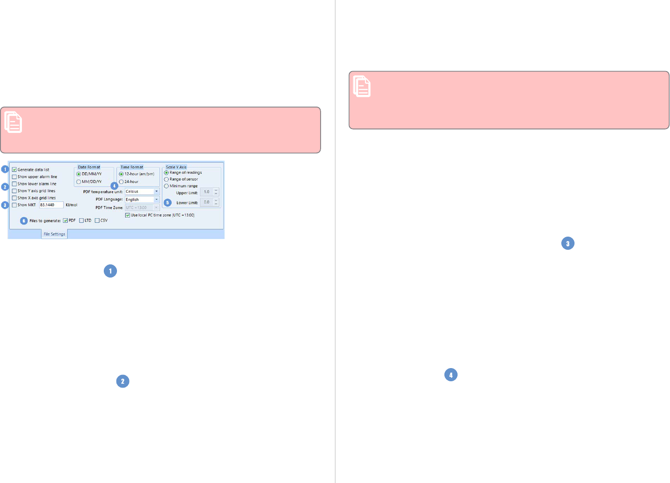
USB Logger File settings
LogTag Analyzer allows you to set additional options for USB loggers,
which decide:
l
which type of files are generated at the end of the trip
l
settings for time, temperature units, MKT parameters and
l
how the individual elements of the generated PDF file will be
displayed.
Note: The appearance of the PDF file can only be defined
during configuration of the logger. It is not possible to alter
the appearance once the USB logger has completed its trip.
Figure 45: File Settings tab for USB loggers
Generate Data List
The PDF file always contains a one-page overview report. Please refer
to the individual USB Product guides for information about the
contents of the report.
Select this check box to show additional data list pages with a single
row for each reading, along with the with date, time and temperature
values, plus any special events that were recorded against this reading.
When you clear this box only the report summary page will be created.
Alarm and Grid Lines
To assist with orientation on the chart, several lines can be shown or
hidden. Following options are available:
Show upper alarm line
Show lower alarm line
Select which alarm line will be displayed on the PDF. Clear the boxes if
you don't wish to see the alarm lines.
The chart will not automatically zoom to include the alarm
lines, if they lie outside the selected Y-axis scale. If you wish
to always see the alarm lines, set a custom range Y-axis zoom
which includes the alarm values.
Show Y-axis grid lines
Show X-axis grid lines
Select which grid line will be displayed on the PDF. Clear the boxes if
you don't wish to see the grid lines.
The position of the grid lines is automatically determined; it depends
on the Y-axis settings and the time span covered by the readings.
Show Mean Kinetic Temperature (MKT)
Selecting this box calculates and displays the MKT value on the PDF
report. If selected, you can accept the suggested default value of the
Activation Energy of 83.144 KJ/mol, or type a custom
ΔH
value in the
text entry field. This value is then used for the MKT calculations.
Typical values range from 60.000 to 100.000 KJ/mol.
When you use LogTag Analyzer to download a USB logger, the custom
value can also be used for the MKT calculations in the software. This is
controlled by a setting in the customization for the Mean Kinetic
Temperature (on page136)
Regional Settings
This group of parameters allows you to customize regional settings of
the PDF report. Usually, this would be set to the region of the person
evaluation the data.
Additional Features for TRED30-16R and TRED30-16CP models
LogTag
®
Analyzer User Guide
page 66

Date format
Select one of the options that corresponds to the date format you wish
to use for the PDF report. You can choose between DD/MM/YY and
MM/DD/YY formats.
Time format
Select one of the options that corresponds to the time format you wish
to use for the PDF report. You can choose between 24- and 12-hour
(am/pm) formats.
PDF Language
Select the language of the PDF generated by the logger. Available
languages are:
l
English
l
French
l
German
l
Russian
l
Spanish
Please note that this feature is only available on newer models. If you
are unable to select a language other than English during configuration,
the feature is not available for your logger. The unit's display always
shows English characters regardless of the chosen language.
PDF Temperature units
Select the temperature units used on the PDF report and in the CSV file
from the list. For USB logger models with display this also sets the unit
shown on the display. It is not possible to configure different units for
PDF and Display, or to configure this after the trip has completed.
PDF Time Zone
You can clear the Use local PC Time Zone box and choose a different
time zone. This is useful if you ship to receivers in a different time
zone and you wish them to see the times in their local time.
If you choose your own time zone settings, you will need to adjust the
time zone for daylight saving yourself. For example, if you want the
PDF data to show the correct time for a user in New York, set the time
zone to UTC-5 during Standard Time and to UTC-4 during Daylight
Saving.
Note: The time zone displayed in the PDF cannot be adjusted
by the receiver! To view the logger's data in other time zones
the receiver will need to download it with LogTag Analyzer and
adjust the displayed time zone. See Date and Time Format on
page182 for further details.
Use local PC Time Zone
When selected, the PDF file will display times and dates in your local
PC's time zone. The time is automatically adjusted for daylight saving.
Chart Scaling
These settings control the zoom level of the chart display. Please note
that you cannot zoom the date/time axis of the chart.
Y-axis scaling
Select one of the available options to scale the temperature axis for the
chart of the recorded readings.
l
Range of readings; this scales the chart area, so the highest and
lowest temperatures recorded are displayed at the top and bottom of
the area. If you choose this option, the maximum screen area is
used to display all recorded readings.
l
Range of sensor; this scales the chart to show the full temperature
measurement range of the logger.
l
Minimum range: When you select this option, the entry fields for
the two temperature values become active. Enter the values you
wish to use as maximum and minimum values for the chart's y-
axis. This is useful if you wish to easily compare readings from
multiple loggers in similar environments.
If readings outside your selected range are recorded during
the trip, the scaling is adjusted so the chart always displays
all recorded readings.
Additional Features for TRED30-16R and TRED30-16CP models
LogTag
®
Analyzer User Guide
page 67

RH-axis scaling
For UHADO-16 loggers, two Y-axis scales are displayed, one for
temperature (left) and one for humidity (right). The scaling selection
made here affects the RH scale only, the temperature is adjusted to
suit.
l
Range of readings; this scales the chart, so the maximum and
minimum recorded humidity values are displayed at the top and
bottom of the area. If you choose this option, the maximum screen
area is used to display all recorded readings.
l
0-100%; this scales the chart to show the full humidity range of the
logger.
l
Minimum range: When you select this option, the entry fields for
the two humidity values become active. Enter the values you wish to
use as maximum and minimum values for the chart's RH-axis. This
is useful if you wish to easily compare readings from multiple
loggers in similar environments.
If readings outside your selected range are recorded during
the trip, the scaling is adjusted so the chart always displays
all recorded readings.
Files to generate
Select which file type the USB logger should automatically create when
plugged into a USB port. Once generated, the files will be accessible on
a read-only drive or mounted device via your file system.
The files created by the USB logger are not automatically
copied to a permanent storage volume on your computer. If
you wish to retain the files you need to manually copy them to
a location such as your Documents folder.
If you clear all check boxes, no files will be generated, and you will
need to access the data with LogTag Analyzer.
USB Loggers
There is a short delay after a USB logger is plugged in, before it can be
accessed by LogTag Analyzer. The logger starts a registration process
with the operating system called USB Device Enumeration. It will take a
few seconds while the operating system loads the required drivers.
l
If LogTag Analyzer is running when a USB logger is plugged in, the
file generation that usually takes place is suppressed to allow fast
communication with the software.
l
If the software is not running, the logger now generates the on-
board files it has been configured for. This process can take some
time, especially if the unit has a full memory buffer and has been
configured to create PDF, CSV and LTD files. While the files are
being generated, the green LED is permanently lit. Loggers with a
display show a blinking USB symbol, or the word 'busy'.
If you need to access the files, and LogTag Analyzer is running, please
close the software and wait for the on-board files to be generated.
Additional Features for TRED30-16R and TRED30-16CP models
LogTag
®
Analyzer User Guide
page 68

Figure 46: Alarm ranges for USRIC-8M
Figure 47: Representation in LogTag Analyzer
USB loggers can be configured for up to 6 different alarm trigger
conditions, depending on the model.
l
All USB logger models have a primary upper and a primary lower
alarm. For some loggers such as USRIC-4, USRID-16 and some older
USRIC-8 and UTRIX-16 models these are the only alarms available.
l
USRIC-8, UTRIX-16, USRID-16W, UTRED30-WIFI and UTRED30-16
allow four freely configurable alarms in addition to the primary
upper and lower alarms, for a total of 6 temperature alarms.
l
UTRID-16 and UTRED-16 allow two upper and two lower alarms in
addition to the primary upper and lower alarms, for a total of 6
temperature alarms.
l
UHADO-16 allows two freely configurable temperature alarms in
addition to the primary upper and lower alarms, for a total of 4
temperature alarms. It allows a single primary upper and lower
humidity alarm, but each alarm can be configured with different,
independent delay values.
Initially, start with the primary upper and lower alarms trigger
conditions and activate additional conditions separately. For each
threshold value you enable, you can set the usual values such as
threshold temperature, activation type and alarm delay value.
You need to observe some basic rules when entering alarm conditions
into the configuration screen in LogTag Analyzer:
l
A primary upper alarm must be entered before more upper alarms
can be entered.
l
A primary lower alarm must be entered before more lower alarms
can be entered.
l
Any additional upper alarms must have higher threshold values
than any previously entered alarm.
l
Any additional lower alarms must have lower threshold values than
any previously entered alarm.
l
You can enter a different number of upper and lower conditions, or
only upper, or only lower conditions, or none at all. You can,
however, not make all alarms upper alarms, and you cannot make
all alarms lower alarms either.
Additional Features for TRED30-16R and TRED30-16CP models
LogTag
®
Analyzer User Guide
page 69
Multi-Alarms in USB Loggers

Figure 48: Entry line for alarm trigger conditions
Figure 49: Entry line for RH alarm trigger conditions
l
Threshold values for adjacent alarms can be equal and combined
with different alarm types and delay time values. For example, you
can enter a primary upper alarm with an 8 °C threshold and 10
accumulative readings, plus an alarm with an 8 °C threshold and 5
consecutive readings. In this instance the alarm will be triggered, if
either 10 readings in total are above 8 °C, or 5 consecutive readings
above 8 °C have occurred.
Any alarm condition that is activated will be shown on the PDF and in
the software.
Dual-Channel loggers
For Dual-Channel loggers, two alarm tabs are presented, one for each
channel. All alarm parameters are set individually for each channel,
except that the red Alert LED will light and the buzzer will sound as
long as one of the channels still has an active alarm.
If only one of the channels is activated in Log Channels, you cannot
enter data into the tab for the other channel.
USRIC-8M and UTRIX-16M models
For a short period in 2017, USRIC-8 and UTRIX-16 models with
multiple alarm threshold values were sold with the suffix M after the
model name, i.e. USRIC-8M and UTRIX-16M. Effective November 2017
this suffix has been dropped from the model designation, and USRIC-8
(from serial number 5035127752) and UTRIX-16 (from serial number
5040022407) now support multiple alarm threshold values. Models
without the M suffix delivered before this date only allow simple alarm
settings with one upper and one lower alarm (they can also not be
upgraded).
If you are configuring earlier USRIC-8 and UTRIX-16 models
that do not support multiple alarm thresholds you will not be
able to select the AdvancedAlarmSettings.
For any loggers that do not support the advanced alarm
settings, only primary upper and lower alarms will be set. The
remaining alarms will be disregarded.
Additional Features for TRED30-16R and TRED30-16CP models
LogTag
®
Analyzer User Guide
page 70

Figure 50: Alarm ranges for UTRID-16
Figure 51: Representation for UTRID-16
For UTRID-16, UTRED-16 and UTREL-16 loggers a slightly different
screen is shown. Here, the alarm symbols that appear on the LCD are
depicted next to the entries in the software. The rules above are the
same with one notable addition; a maximum of three upper and three
lower alarm conditions can be entered.
The way alarms are shown on loggers with a display depends
on the model. Please refer to the particular model's product
user guide for information on what symbols will show with
what alarm.
Additional Features for TRED30-16R and TRED30-16CP models
LogTag
®
Analyzer User Guide
page 71

Updating USB Loggers
Starting with version 3.1 release 10, LogTag Analyzer allows the option to update USB loggers
directly through the software, rather than via separate apps.
Figure 52: An update is available for a USB logger
From time to time LogTag North America Inc will publish updates that can be applied to a USB
logger to enhance functionality and add new features, or to improve how the logger currently
works.
This feature can be enabled or disabled in the General Settings (on page149).
You will need an active internet connection and access to the LogTag North America
Inc website at logtagrecorders.com to be able to use this feature.
If the feature is enabled, you will be given the option to update any logger for which an update
is available, as part of the configuration process.
You will see:
l
the model ID of the USB logger for which an update is available
l
if the update is critical (an existing feature isn't working as expected) or a feature update
(new functionality or enhanced features are available)
You can find more information about the new and updated features on the LogTag
®
USB
Logger Update page.
l
a progress bar once you have started applying the update
Additional Features for TRED30-16R and TRED30-16CP models
LogTag
®
Analyzer User Guide
page 72

To start the update process, click Apply Update. The progress bar indicator changes according to
this sequence:
(the logger is being switched to accept the update)
(the current firmware is erased)
(the update process is about to start)
(the update is in progress)
Figure 53: The update has successfully completed
During the update process the logger's Alert LED will be permanently on. For models with a
display, the word boot will appear.
You should not remove any loggers during this process. If, however, the update process is
interrupted, you may see this on the screen:
If this happens, simply start the logger configuration from the beginning.
You can skip the update process by clicking Skip Update. You will then be presented with the
normal configuration screen.
Once the upgrade has successfully completed, you will see this confirmation screen:
Keep the logger connected until you see the Configuration screen, then continue as normal
with the configuration.
If -for some reason- the upgrade process fails, and your logger continues to show boot or a red
LED, please follow the steps in Recovering from a failed firmware update (on page210)
Additional Features for TRED30-16R and TRED30-16CP models
LogTag
®
Analyzer User Guide
page 73
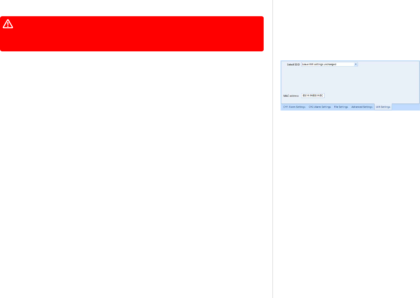
Wireless Connection Parameters
Factory-new UTRED30-WIFI or UTREL30-WIFI loggers do not contain any wireless LAN
settings. Although you can configure your wireless settings in LogTag Analyzer, we
strongly recommend you run the WiFi Connection Wizard first before configuring the
recording parameters here.
Figure 54: WiFi Settings tab for units without a WLAN configuration
When configuring a logger with built-in wireless capability such as the UTRED30-WIFI, an
additional tab is available, allowing you to enter the connection details for your Wireless
Network (WLAN, WiFi Network).
Since units from the factory do not come with any pre-configured wireless connection data,
you will need to enter details here when you configure a device for the first time.
You will need to have the following details available to connect to your WLAN:
l
SSID (Service Set IDentifier) or Network Name
This is the identification of the wireless network you wish to connect to.
Click Select SSID to show a list of available networks. Select one of the network names from
the list of available networks.
l
Wireless Security Settings
This is sometimes also called the Authentication Method. You need to ensure the logger is
configured for one of the authentication methods your network supports:
o
WPA2-PSK
This is one of the most common connection methods for small businesses, which only
requires a password and the network name to be set correctly in order to connect to the
network.
o
Open
This security method does not require you to enter a password, however, open networks
often require a login on a special web page called a captive portal. Although newer
models of the UTRED30-WiFi supports open networks, it does not support a captive
portal. Your IT administrator can add an exception in your network, so your logger can
still connect.
o
EAP-PEAP (with MSPCHAP2)
EAP-PEAP is an enterprise authentication method, which requires a username and
password to connect to the wireless network. Your IT administrator will be able to tell
you if your organization uses such a method, and what you need to enter.
Additional Features for TRED30-16R and TRED30-16CP models
LogTag
®
Analyzer User Guide
page 74
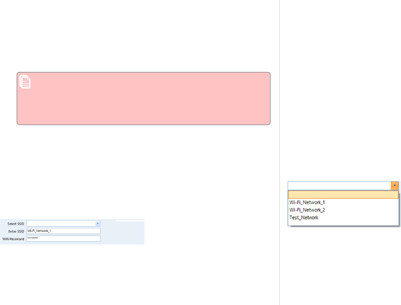
o
Other
Occasionally, we may provide new authentication methods for our wireless loggers
through an updated Connection Wizard, and someone else may have configured these
settings in the logger for you. If LogTag Analyzer detects one of these new authentication
methods, it will still show the configured SSID when you click Select SSID, however, it
will not be able to identify the authentication method, but display "Other" instead. You
can also not see password or user name entry fields. Unless you wish to connect to a
different network, we suggest you click "Leave WiFi settings unchanged", this will ensure
the wireless settings stored already inside the logger will remain unaltered.
Note: You can change the authentication to a known method, but once the logger
is configured, you will not be able to restore the previous authentication method
with this version of LogTag Analyzer. This can only be done using the same
software that generated the new authentication method in the first place.
If during configuration you are not offered a specific authentication method,
your logger does not support that method.
l
WiFi Password
This is sometimes also called the Network Security Key, Pre-Shared Key (PSK), Passphrase or
simply the Network Password. This is required for all WPA2-PSK networks.
l
User name, Password
When you use an enterprise authentication method, you will need to provide a user name
and a password to be able to connect to the network.
Figure 55: Available wireless networks
If necessary, your IT Network Administrator can advise you of these settings, usernames and
passwords.
If the network to which you want to connect the logger is not in range or hidden (in other
words, it does not appear on the list of networks), you will need to specify the settings by
typing the SSID and password of that network, once you have clicked Select SSID.
This is required, for example, if you intend to deploy the device at a location with a different
WLAN to what is available at your current location.
Additional Features for TRED30-16R and TRED30-16CP models
LogTag
®
Analyzer User Guide
page 75
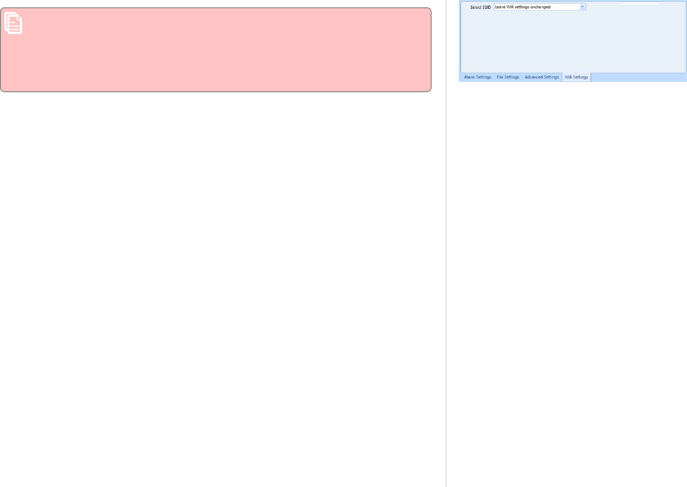
Figure 56: WiFi Settings tab
Please note that LogTag Analyzer does not check the validity of SSID or password.
Please ensure that the correct password is entered. The majority of connection errors
are a result of entering an incorrect password.
LogTag Analyzer will allow you to configure a logger with an empty SSID. This is
equivalent to disabling WiFi and you will get a warning symbol and a tooltip in the
Progress Pane indicator that such a logger will not connect to any wireless networks.
When re-configuring a UTRED30-WIFI at a later stage, you have the option to leave the
settings unchanged. This is the default setting offered when you re-configure the device.
Additional Features for TRED30-16R and TRED30-16CP models
LogTag
®
Analyzer User Guide
page 76

Using the LogTag
®
Online Connection Wizard
To enter WLAN settings you can also use the LogTag
®
Online Connection Wizard.
The LogTag
®
Online Connection Wizard is available by clicking Connection Wizard from the
LogTag Online menu, or from the Windows Start menu in the Start - Programs - LogTag
Recorders shortcut folder. The connection wizard allows you to:
l
configure wireless and network parameters of your WiFi enabled loggers
l
configure wireless and network parameters of your WiFi enabled interfaces
l
create an account with LogTag
®
Online (or sign in if you already have an account)
l
register wireless devices against your account
You can find more information about the LogTag
®
Online Connection Wizard at
http://lt.help/c843e.
Additional Features for TRED30-16R and TRED30-16CP models
LogTag
®
Analyzer User Guide
page 77

Using the LogTag Access Wizard
Figure 57: LogTag Access Wizard from toolbar
Figure 58: LogTag Access Wizard from menu
You can use the LogTag®Access Wizard by either clicking the toolbar icon (as shown) or by
selecting Wizard from the LogTag menu.
The LogTag
®
Access Wizard performs following tasks:
1. All connected interface cradles and USB ports are checked for attached LogTag
®
products.
If any of them contain previously recorded data these are downloaded and saved.
2. The configuration window is displayed.
The Wizard performs the functions Downloading and Configuring in sequence, so you do not
lose any data.
Note: While the wizard is visible the Automatic download feature will be temporarily
disabled. You will also not be able to access the Wizards while an automatic download
is in progress.
When the wizard completes, you can click Restart Wizard, and the process will start from the
beginning.
Quickly re-configuring a LogTag
®
logger
Figure 59: LogTag
®
quick-reconfigure function
You can configure a LogTag
®
logger without first displaying the configuration screen. To do
this, you can click Quick Re-Configure from the LogTag menu, and you will see the Upload
configuration screen, where a logger will simply be re-configured with the settings used for the
previous trip.
You can also press the F6 function key.
There are certain rules when using this function:
l
You can use multiple interfaces. Each LogTag
®
device detected in an interface is re-
configured with the same data used for its previous trip. Loggers do not have to be of the
same model, and can each have different configuration settings.
l
Re-configuration is only possible for loggers which used the "Push button" or the "Push
button from hibernation" start method for their previous trip. If the logger's previous trip
was started by the date/time start method the quick re-configure option will result in an
error message being displayed.
l
If a logger requires a password for configuration you will be requested to provide this
password. If you enter an incorrect password, the configuration process will be aborted.
Additional Features for TRED30-16R and TRED30-16CP models
LogTag
®
Analyzer User Guide
page 78

l
If the unit is still logging when you reconfigure it, you will be asked to confirm whether or
not you wish to stop the current trip.
Automatic Re-Configuration after Download
To process loggers even faster, you can set-up an option to re-configure a logger with the same
settings after it has been downloaded by using the automatic download option.
This feature is set up in the Automation section of the general options by selecting Re-
configure with same settings after automatic download.
Once enabled, a logger is automatically downloaded once inserted in the interface cradle, and
immediately re-configured for logging, using the same settings as for the trip just completed.
You will receive a confirmation once the configuration is complete.
Figure 60: Confirmation request to allow stopping the logger
If the logger is still logging during download, you also need to acknowledge that it must stop
recording before a re-configuration can proceed.
Please note this option only works when a logger is automatically downloaded when inserted
into the interface, i.e. the "Enable automatic download of readings from Loggers" option must
be enabled, and the download triggered by inserting the logger into the interface. This does not
apply when the product is downloaded through the menu of by pressing F4.
If the logger you have downloaded does not have a configuration password and has also
finished logging, the only visual feedback on the PC will be after the logger has already
been re-configured for a new trip You will only be able to access the data from the trip
just downloaded on the PC, but not within the logger. Therefore, if the file location for
storing data is not accessible at the time of downloading, the re-configuration will not
proceed.
Continuous operation
All LogTag
®
products have a limited amount of memory to store the readings they record.
When selecting the option to Record readings continuously, the LogTag
®
will not stop once the
memory is full; instead it will replace the oldest reading stored with the newest reading.
Not every model supports continuous operation. If you configure a LogTag
®
and you cannot
select this option, your model does not support this feature.
Additional Features for TRED30-16R and TRED30-16CP models
LogTag
®
Analyzer User Guide
page 79

Pre-start data collection
LogTag
®
products support a feature called pre-start logging, which can be selected during
configuration.
When pre-start logging is enabled, the logger will automatically start recording as soon as
configuration is completed. It will record at the same sampling interval as defined in the
configuration and will continue to record until the user starts the product by pressing the
START/MARK button. Once started, it will record started readings as per the configuration
settings. While the LogTag
®
is recording pre-start readings the Alert LED will not activate,
even if an alert condition is present.
Pre-start logging is useful as a fail-safe recording setting so if the logger accidentally is not
started at the appropriate time, the readings will still be available to view later.
When the readings are retrieved later, any pre-start readings will be separately displayed, so
the user can quickly identify the readings recorded before and after the logger was started.
All LogTag
®
models have a finite amount of memory to store the readings they records.
Therefore, while the logger is recording pre-start readings it will operate in its 'continuous
operation' mode, which is explained further in the section Continuous operation on the
previous page. Once its memory is full, the oldest pre-start reading will be overwritten with
the latest pre-start reading, or the latest started reading if the logger has been started.
Once started, the logger will first fill any remaining memory, then overwrite the oldest pre-
start readings until the complete memory is filled with started readings.
If a LogTag
®
product has been configured to start recording at a certain date/time, or for push
button start from hibernation, no pre-start readings will be recorded.
Restricting Access
You can enable a password protection feature, which requires any user to enter the correct
password when they next configure the LogTag
®
logger for recording. This prevents a user
from accidentally erasing data
Figure 61: Password entry
During configuration, select Configure requires a password. A password entry field appears,
where you can enter a password.
A confirmation of this password is required.
Additional Features for TRED30-16R and TRED30-16CP models
LogTag
®
Analyzer User Guide
page 80

Tip: Sometimes users tick the password required box, but don't enter a password. Such
a "blank" password is valid, hence the password request dialogue will appear when re-
configuring such a unit. In this case simply selecting OK will advance to the next
screen. A warning message will inform you when you are using a blank password.
Protecting Recorded Data
Not only can you protect a logger's configuration; most models can also be set up so they
require a password before you can access recorded data. This function can be enabled in the
main configuration screen by selecting Download requires password. The same password is
used to protect configuration and download.
The features can be used independently. You can use a download password without a
configuration password, and vice versa, or use both passwords, or none.
Note: For USB loggers, Download requires password cannot be enabled if you enable
any on-board files to be generated.
Password Rules
The password can be up to 6 characters long (16 characters for USB loggers) and can contain a
mix of letters, numbers and special characters. The selected input language of the computer's
operating system determines which special characters can be selected.
If a user decides to make use of special characters, extra information about the language used
is stored inside the recorder. Users will then need LogTag Analyzer 2.3 Release 7 or later so the
password is correctly interpreted.
This feature is not available in USB loggers.
If you use special characters for languages such as Japanese or Chinese the maximum number
of characters that can be used will be reduced due to the increased memory required to store
the characters.
Please see Code Pages on page196 for a more detailed explanation.
Additional Features for TRED30-16R and TRED30-16CP models
LogTag
®
Analyzer User Guide
page 81

Verify Access Password
Figure 62: Password confirmation
If the Configure requires a password option was enabled or the password was changed during
the configuration process the user is required to verify the password before it will be stored in
the logger. A window similar to this will appear:
Once a password has been stored in the device, it can only be accessed by providing the correct
password. Therefore, if you forget the password you will no longer be able to access the
LogTag
®
Passwords are case sensitive - the passwords "Bob" and "bob", for example, are
different.
Hibernation - Prolonging battery life
If your LogTag
®
device is not going to be used for extended periods of time you should
hibernate it. While in Hibernation it will consume minimal power, which will extend the
battery life when compared with leaving an idle LogTag
®
device operating.
While a logger is hibernated it will:
l
not record and store any new readings;
l
not activate the Alert and OK lights; and
l
not respond to the START/MARK button being pressed.
Figure 63: Hibernating a logger
The only exception is when the logger has been configured for Push button start from
hibernation in the configuration screen. In this case pressing the START/MARK button will
'wake' the product and commence logging according to the configured settings. Not every
model supports this feature.
To 'wake' a hibernated logger, go through the usual process of Configuring a LogTag® product
for recording (on page48).
To hibernate a logger, select Hibernate... from the LogTag menu.
You can also use the F5 function key.
Additional Features for TRED30-16R and TRED30-16CP models
LogTag
®
Analyzer User Guide
page 82

Figure 64: Hibernating multiple loggers
You will see the window one on the right when hibernating a logger.
One of the following icons will show next to each of the items in the list:
l
(No picture) indicates the logger is still in the process of being hibernated.
l
The logger was successfully set to hibernation
l
The software was unable to set the logger to hibernation
Once a LogTag
®
device has been successfully hibernated it should be removed from the
Interface Cradle before pressing any other button. As soon as the software communicates with
a hibernated logger (for example through automatic download) it will be returned to normal
operation.
The extent to which Hibernation will prolong the battery life of a LogTag
®
product varies
between different models and versions.
Starting and using the LogTag
®
logger
Once a logger has been successfully configured, it must be started to take readings.
A logger can start automatically at a date and time set during configuration, or manually by
pressing the START button on the logger.
The different start methods are explained in more detail in the section about Configuration
Parameters.
For exact procedures how to start a logger please refer to the individual Product User Guides
and Quickstart Guides, available for download from the product web pages at
https://logtag.com.
Additional Features for TRED30-16R and TRED30-16CP models
LogTag
®
Analyzer User Guide
page 83

Figure 65: LogTag Profile Menu
Figure 66: Configuration Profiles Main Window
Configuration Profiles
To simplify the task of configuring multiple loggers with the same
parameters, you can store the settings you would enter during
configuration (such as alert limits, logging interval, number of
readings etc...) in a Configuration Profile, then use the profile to
configure loggers as required.
Configuring a logger with a pre-defined profile requires only three
steps:
1. Select Profiles from the LogTag menu.
The window now displayed gives you an overview of the profiles
already installed. You can also add new profiles or edit and
delete existing ones.
2. Select the profile you wish to use in the Configuration Profiles
main window.
3. Click Configure loggers.
The next few pages detail the steps required to add and manage
configuration profiles.
Additional Features for TRED30-16R and TRED30-16CP models
LogTag
®
Analyzer User Guide
page 84

Profiles Grid
Figure 67: Profiles in the profile grid
When you first select this feature the profiles grid will be empty. You will fill the grid by adding
profiles, or importing profiles.
Profiles from the grid can then be used to configure loggers. A single click on the column title
will sort the profile using this column. Double-clicking on a profile will configure all loggers
currently in connected interfaces using the parameters stored in the configuration profile. You
can select multiple profiles for export or deletion when you hold down the CTRL key while
clicking, but you cannot edit or apply more than one profile at the same time.
Profile Control Buttons
Figure 68: New profile window
Clicking on a profile row and clicking Configure LogTags will configure all loggers currently
attached, using the parameters stored in the profile (you can also do this by simply double-
clicking the profile name).
To be configured, loggers must have the same model name as in the profile.
Use the control buttons to add new profiles and to edit or delete existing profiles.
Clicking New will bring up the Edit Profile window without any parameters. Type a Profile
Name into the text entry field and select a Model from the list.
Once you have selected a model, the configuration parameters for this model appear. They are
the same parameters as already described in Configuring a LogTag® product for recording
When you enter the configuration parameters for a WiFi enabled logger, but do not
enter any WiFi settings, any logger configured with that profile will not connect to a
WiFi Network. Use the WiFi Wizard to connect this logger to the desired WiFi network.
Additional Features for TRED30-16R and TRED30-16CP models
LogTag
®
Analyzer User Guide
page 85

Figure 69: Editing a TRIX-8 profile
The same window will be displayed when you click Edit. Every entry field is now populated
with the saved value for this profile. Any entry field can be edited, with the exception of the
model type and the profile name.
Click Save to store the profile in the Profile file, Cancel to discard any changes and Help to
display the help screen for this window.
Profile Storage File Name and Path
The collection of profiles displayed in the profiles grid is saved in a single file on your PC,
which is called the Profile File. This file is typically stored in a folder called LogTag
Configuration Profiles inside the My LogTag Documents folder. Every time you open LogTag
Analyzer this profile file is activated.
You can select alternative collections by opening different files. This can be useful if for
example you want to keep different profiles for different customers, or you prefer to separate
and organize your profile collections.
You can click on the button and select a different profile file. If you have unsaved changes
you will be asked to confirm if you want to first save these changes. An explorer window will
then open, where you can select a new profile file.
Note: To create a new profile file, export one or more profiles to a new profile file. You can
then open the new profile file and add, edit or delete profiles as usual. Alternatively, you can
download an empty profile file template from http://lt.help/68jib.
Profile File Controls
If you have stored your profiles in different profile files, you can transfer data between
different files with the Import and Export buttons.
Figure 70: Prompt when overwriting an existing Profile
When you click on the Import button, a file explorer window will open. Browse to the profile
file from which you want to import the profiles and confirm your selection by clicking Open.
All profiles from the selected profile file will be imported into the currently active profile. If a
profile is imported that has the same name as an already active profile, you need to confirm
whether you wish to skip the import of this profile or overwrite the active profile with the
imported profile.
You can export selected profiles to a new file by highlighting a profile and clicking Export. A
file explorer window will open, where you can enter a new profile file name (the file will be
created when you click Save), or overwrite an existing profile. If a profile is exported, and a
profile file already exists, you need to confirm whether you wish to cancel the export of this
profile or overwrite the profile file. You can export more than one file at the same time by
selecting the desired files while holding down the CTRL key.
Additional Features for TRED30-16R and TRED30-16CP models
LogTag
®
Analyzer User Guide
page 86

You cannot amend a profile file by exporting a profile to it. Exporting a profile will
always overwrite the target profile file.
Profile Dialogue Controls
Clicking Save and Exit will store the profile in the location entered above. Clicking Cancel will
discard any changes and return you to the main window.
Please note there are some restrictions when you work with configuration profiles:
l
Configuration profiles cannot use the date/time start mechanism. If a defined start time
were to be applied to a profile, this time would most likely have passed by the time the
profile is applied. If you need to configure a number of loggers and you want them all to
start at the same time you should use the standard configuration method and the Repeat
function.
l
You cannot configure one type of logger model with a profile written for another model.
l
You cannot have multiple profiles with the same name.
l
If you have exported a profile to a profile file, canceling the main edit window will not undo
the changes.
l
If you try to apply a profile to a logger with a password protected configuration, this same
password must be provided in the profile. There is no separate password confirmation
dialogue.
l
Loggers that can be upgraded to use a download password will automatically be upgraded
when a profile is applied using this feature.
Additional Features for TRED30-16R and TRED30-16CP models
LogTag
®
Analyzer User Guide
page 87
Sometimes a logger cannot be configured using a particular profile. In this case one of the
following errors will be displayed:
Message What it means
"Logger does not
support advanced
alert settings"
You have selected a profile which has separate upper and lower alert settings, but
the logger you wish to configure does not support this. You will need to use a
different profile, or use a different logger if this feature is important for this trip.
"Logger cannot
record more than
X readings"
You have selected a profile that requires the logger to take more readings than fit
into its memory. You will need to use a different profile, or use a different logger if
this feature is important for this trip.
"Password in
profile does not
match logger
password"
You have selected a profile with a password, and the password currently stored in
the logger is different. You will need to use the normal configuration process to
remove the password; after that you can use the profile function to configure the
logger with the new password. If the logger does not allow the password to be
changed, you will need to use a different profile.
"A password
cannot be applied
to this logger"
You have selected a profile with a password, but the logger is factory configured so
the user cannot change or enter a password. You will need to use a different profile
that doesn't have a password protection, or use a different logger if this feature is
important for this trip.
"Logger only
supports latched
master alarm"
Loggers typically can have a setting applied that allows an alarm to reset if
conditions go back to within specification. Some older TRID30 loggers do not
support this feature, and if you attempt to configure such a logger with a profile
using this setting you will see this error. You will need to use a different profile or
use a later model TRID30 if this feature is important for this trip.
"Profile logger
type does not
match"
You are trying to configure a unit with a profile that was created for another model.
A profile is specific to a logger model, so you will need to use a different profile.
"Lease expired.
The max. number
of starts has been
reached."
You are trying to configure a unit which has no more trips left. You will need to use
a different logger.
Table 13: Profile error messages
Additional Features for TRED30-16R and TRED30-16CP models
LogTag
®
Analyzer User Guide
page 88

Figure 71: Factory Calibration Certificate
Starting with version 3.1.6, you can view and print a logger's factory calibration certificate
directly from LogTag Analyzer.
You can access the certificate:
l
by clicking Show Certificate from the report tab after the logger was downloaded
l
by clicking Certificate of Calibration during configuration of the logger
The certificate issue date is the date the logger was first configured.
You can also access the factory calibration certificate from the report tab when opening a saved
data file, provided the recorded data are from the period during which the certificate was still
valid.
You will not be able to access the certificate:
l
before the logger is configured for the first time. You will not be able to click Show Certificate
until the configuration is uploaded successfully to the logger
l
after the logger was adjusted by a third-party calibration laboratory using LogTag
®
Calibrate
l
if a logger was manufactured before 1. April 2019
l
for indicator products
l
on a multi chart report
If a logger was first configured with a version of LogTag Analyzer prior to 3.1r6 you
may still be able to view the calibration certificate. Please note, however, that the
certificate date may differ from that on the certificate issued by your distributor. In
this case, the distributor issued certificate is correct.
For additional information you can click the icon next to the calibration certificate button:
Even if you choose not to view the certificate, a PDF of the certificate document will be saved
to "My LogTag Documents", in the "Certificates" folder when you configure a logger for the
first time.
Additional Features for TRED30-16R and TRED30-16CP models
LogTag
®
Analyzer User Guide
page 89
Calibration Certificates

Figure 72: Calibration certificate with multiple tabs
Starting with version 3.2r2, LogTag Analyzer can show additional calibration information for
LogTag data files from loggers that used Smart Probes to record temperature, in addition to the
logger's own certificate.
Following applies when viewing these certificates:
l
When you display the contents of a data file from a logger, that had Smart Probes connected
when it was recording, up to two additional tabs are available in the certificate window.
The tabs show :
o
The calibration certificate for the logger itself.
This certificate only applies when the logger is operated with an ST10 or ST100
analogue probe.
o
The certificate for the Smart Probe connected to channel 1.
o
The certificate for the Smart Probe connected to channel 2.
Either tab will only be shown if a Smart Probe was connected to this channel during
logging.
l
Click the corresponding tab to display the certificate for the Smart Probes.
Additional Features for TRED30-16R and TRED30-16CP models
LogTag
®
Analyzer User Guide
page 90
Smart Probes
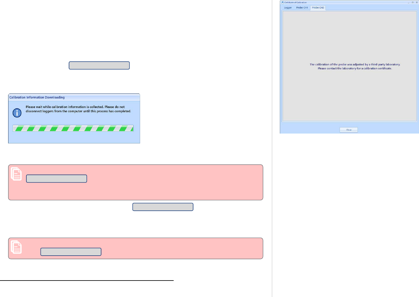
Figure 73: Probe calibration was adjusted
l
If a Logger or Smart Probe were calibrated and adjusted by a third-party laboratory, a
message will be displayed on that tab, as shown on the right.
You can also view certificates for Smart Probes currently connected to a logger during the
configuration process:
l
If a logger is being configured for the very first time, the calibration information for both
the logger and the probes can only be accessed after the logger has completed the
configuration process.
l
To view the calibration information for the Smart Probes, these must be connected to the
logger when you click Certificate of Calibration after the configuration has finished. At this
point, LogTag Analyzer interrogates the logger to determine if Smart Probes are connected,
and to retrieve their information.
1
During this time you will see a warning message, asking
you not to remove the logger from the PC.
l
When this process is complete, you will see the Certificate tab for the logger, plus any Smart
Probe certificates.
The logger's certificate will be automatically stored, even if you do not click
Certificate of Calibration (this is the same as with other logger models). To store the
Smart Probe certificates, however, you will need to view the certificates, so the
Calibration information can be downloaded from the probes.
l
If a logger was previously used, you can click Certificate of Calibration even before the
configuration data have been transferred to the logger. In this case, any Smart Probe
certificates displayed in the tabs will be of the probes last connected, which may be
different to the currently connected probes.
You can only view the certificates for the currently connected Smart Probes if you
click Certificate of Calibration after the logger configuration is complete.
1
This process will proceed, even if no Smart Probe is connected to either logger channel.
Additional Features for TRED30-16R and TRED30-16CP models
LogTag
®
Analyzer User Guide
page 91

Once a LogTag
®
has finished its trip, you can:
l
download the data to a PC (the section below explains this in more detail);
l
view and analyze the information (as detailed in the section Analyzing the results; and
l
print the information or save it to other formats (as shown in Printing the results).
LogTag
®
products store all recorded data in their internal, non-volatile memory. You can
download the data as many times as you want, as long as the logger is not re-configured or
hibernated.
When you download the data, a file is automatically created in a pre-defined folder. Typically
this is the C:\Users\User\Documents\My LogTag Documents folder, but it may also be a folder
in Public Documents. You can customize this location to your requirements File and Folder
Settings as described on page171.
Downloading data stored in a logger does not erase the data from memory, however if you have
enabled the "Automatically re-configure..." option you will no longer be able to access the data
in the logger once this process has started.
If the LogTag
®
is currently recording while you retrieve the information, it will continue to
record without interruption. If the logger is in the process of taking a log you may see a slightly
longer download time as communication pauses to allow the log to be taken.
There are three ways to retrieve the recorded results from a LogTag
®
logger:
l
via automatic download
Figure 74: Downloading a LogTag
®
automatically
Slot the product into the interface cradle, or plug it into a USB port while the LogTag
Analyzer software is running (even when minimized). If the automatic download feature is
enabled, the software will automatically retrieve the recorded readings, save the information
to your disk drive and display the information. While the software is retrieving the readings
you will see an animation. A new animation will be displayed for every new logger attached.
You can also enable the option to automatically re-configure the device with its current
settings (see Automatic Re-Configuration after Download on page79).
Additional Features for TRED30-16R and TRED30-16CP models
LogTag
®
Analyzer User Guide
page 92
Results from LogTag
®
Loggers

Figure 75: Download Menu
Figure 76: Wizard Toolbar Icon
l
via the menu system
Click Download from the LogTag menu.
You can also press the F4 function key.
l
Using the Wizard
Click the LogTag
®
icon on the toolbar or click on Wizard from the LogTag menu.
The wizard retrieves the readings stored in the logger and then offers to configure it for its
next trip.
Progress Pane
Figure 77: Progress Pane when downloading data
When you initiate the download manually, rather than using the auto-download feature, the
LogTag Download window will be displayed. Each logger found will be listed in the Progress
pane, much the same as in the Configuration Window.
When you see this icon displayed, communication was established, but no data were
downloaded. The most likely cause is that there are no readings in the logger.
When you see this icon, no logger was found in the attached interface.
Data from this logger was downloaded, but the logger has a low battery. It should not be
used for another trip
This icon is displayed after the logger has been successfully downloaded and the data saved.
The progress bar will also show the word Downloaded
This icon is displayed after an unsuccessful attempt to download the logger. Further error
messages will be displayed to indicate why the logger was not downloaded.
When the logger has completed its trip and you wish to see the recorded readings, place the
LogTag
®
into the Interface Cradle.
Additional Features for TRED30-16R and TRED30-16CP models
LogTag
®
Analyzer User Guide
page 93
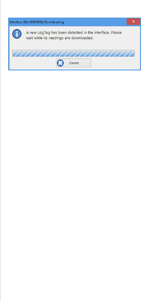
If the LogTag
®
is still recording it will continue to do so. A USB logger, however, will not record
temperatures while plugged in; instead it will record Paused readings.
Figure 78: Downloading a LogTag
®
logger
The software will automatically download any readings and save them in a file.
Once the readings have been successfully downloaded, the software will display the
information. The chapter Results from LogTag® Loggers on page92 explains in more detail
what information is displayed and how you can influence its appearance.
Your LogTag
®
may now also be reconfigured for another trip with the same settings as before,
if you have this option activated (see Reconfigure with same settings after automatic download
on page160.)
Additional Features for TRED30-16R and TRED30-16CP models
LogTag
®
Analyzer User Guide
page 94
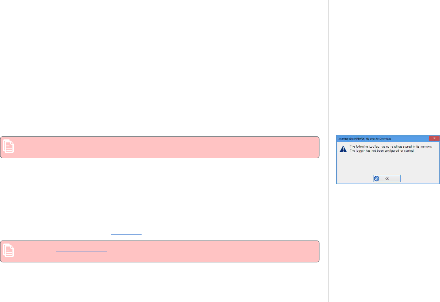
LogTag
®
Data files
Every time you download a LogTag
®
Logger to your computer the data are automatically saved to a file with a
*.ltdx file extension (LogTag
®
Data Extended). This file is then opened, and presented to you on screen. When
you download a LogTag
®
product, and view the data, you are therefore viewing the file that was saved when the
LogTag
®
was downloaded.
The *.ltdx file is unique to LogTag
®
products and can only be read by LogTag Analyzer software.
You can customize a number of options for this file in the Edit - Options window:
l
You can define the file's name, for example by specifying details about the logger from which the data were
downloaded (File Name on page172)
l
You can decide if existing files with older data should be overwritten or kept (Uniqueness on page177)
l
You can automatically have files sent to email recipients and FTP sites (Automation on page160)
l
You can decide which additional other file formats are created, for example PDF files (Exports and Reports on
page179)
You can also combine data from multiple files as on page99.
Please refer to the respective sections in this user guide for more information.
Figure 79: No Readings to download!
Note: If the logger you are downloading has not taken any readings, a message such as the one one on
the right will be displayed.
File generation for Dual-Channel loggers
When downloading Dual-Channel loggers, such as the new UTRED30-16 or UTRED30-WiFi models, several files
will be generated:
l
a *.ltd file, containing the complete data for both channels
l
a *.ltdx file, containing only the data for channel 1
l
a *.ltdx file, containing only the data for channel 2
Both *.ltdx files will be saved, then opened and be presented in the selected default tab. File names will be
generated as usual, with the suffix CH1 and CH2 added as appropriate. The *.ltd file will only be saved, but not
opened, and will also not appear in the Recent File list.
Note: If your default file format is set to *.ltdx, the *.ltd file will be deleted once both *.ltdx files have
been generated.
If you decide to open the *.ltd file again, instead of the *.ltdx file, no new files will be generated. Instead, the
already saved file will be opened, including any changes you have made, such as 120.
Digital signatures
Additional Features for TRED30-16R and TRED30-16CP models
LogTag
®
Analyzer User Guide
page 95

Support for digital signatures is primarily provided for compliance with the US FDA 21 CFR Part 11 regulation -
Electronic records and electronic signatures. Various industries, however, may find inclusion of digital signatures
beneficial for their quality control and assurance systems.
Digital signatures allow users to record an event in a LogTag Analyzer file along with their digital signature. To
add digital signatures to data files, LogTag Analyzer must be connected to the LogTag
®
User Server software. For
more information how to connect see User Server on page186, or contact your local network administrator.
Figure 80: Digital Signatures toolbar button
To add a signature to a file, open the file and click Digital Signatures from the Edit menu, or click Signatures
located on the toolbar, which will display the File Properties window with the Digital Signatures tab already
activated.
Then click New to start adding a digital signature.
Once the Add Digital Signature dialog box appears, enter your LogTag Analyzer user password and select the
meaning for the digital signature that is being added.
Click OK to permanently add the digital signature to the file or Cancel to abort. Multiple digital signatures from
the same or different users can be added to a single LogTag Analyzer file. You can see all digital signatures that
were applied to a file when Viewing file properties (on page98) or in the Report Display on page124.
Note: The time and date displayed in the signature window is always UTC, regardless of the date and time
settings made in Date and Time Format on page182.
How secure are my data
LogTag
®
files are encrypted and contain checks to detect if the file changed since it was originally created. If
LogTag Analyzer detects that a file has been tampered with, or has become corrupted, it will not open the file.
In addition, LogTag
®
devices automatically insert error detection codes during recording, which are used to detect
data errors. When these detection codes for a block of recordings fail the integrity validation, the relevant
readings are marked as non validated readings. Non validated readings are displayed differently to validated
readings to indicate that they have failed this integrity test.
Non validated recordings typically occur in the following scenarios:
1. One or more readings in the non validated block of readings is not the genuine recorded value.
2. A communications or hardware failure has occurred during the transfer of the data from the LogTag
®
to the
computer. Try downloading the recordings from the LogTag
®
again; make sure the contacts on the back of
the LogTag
®
are clean, the contact pins in the Interface Cradle slot are clean and return evenly to their
normal position when the LogTag
®
is removed.
As the software does not modify any of the recorded data in a LogTag
®
file at any time, if the software can open
the file, regardless of how long ago it was created, the contents of the file will still represent the original recorded
information retrieved from the LogTag
®
.
Therefore, the files created by the LogTag Analyzer software meet all criteria for data integrity and data security
as set out in the US FDA 21 CFR Part 11 regulations. The firmware code that is embedded in the processor chip of
Additional Features for TRED30-16R and TRED30-16CP models
LogTag
®
Analyzer User Guide
page 96

each LogTag
®
cannot be extracted or reverse-assembled. Accordingly, data sets that are recorded in the memory
of the LogTag
®
cannot be downloaded or modified except by being transferred to a LogTag
®
file. There is no way
to interfere with the process of the transfer of information between the LogTag
®
and the software in such a way
that data integrity would be compromised.
Additional Features for TRED30-16R and TRED30-16CP models
LogTag
®
Analyzer User Guide
page 97

Viewing file properties
Figure 81: File properties Menu
The file properties window provides users with a summary of the key
properties of the data included in the file, such as model ID and serial
number, alert range and range of readings, start time end time and
total number of readings as well as the battery status. If the LogTag
®
has a limited number of trips left, this is also indicated here.
Figure 82: File properties
The file properties window is accessed by clicking on Properties in the
File Menu or via the toolbar command.
Additional Features for TRED30-16R and TRED30-16CP models
LogTag
®
Analyzer User Guide
page 98

Saving a Multi Chart File
If the main LogTag Analyzer window currently displays a multi chart (see Combining charts onto a single chart), you can save it by clicking on the
toolbar or selecting Save from the File menu. Select a file name and location for your multi chart file. The file extension for multi chart files is
*.multix.
A multi chart file contains a copy of each individual file that makes up the chart along with any zoom settings, annotations and the information that
describes which relation the data files have to each other.
To open a previously saved multi chart configuration file, click on the toolbar icon or select Open from the File menu , then select the "*.multix"
file to be opened. To save a multi chart file under a different name, select the Save As command from the File menu and enter a new file name.
You can save a multi chart file as a PDF, but not as any of the other export file types.
Selected LogTag
®
Data files (*.sltd)
The file type *.sltd is a legacy file type, which you can open with this version of LogTag Analyzer. In this file LogTag Analyzer version 2.X allowed you
saving data zoomed to a particular time window. When opening a *.sltd file, LogTag Analyzer version 3.X will extract the data for the complete trip
and present the data zoomed to the time window stored in the file.
Since the new *.ltdx format has this function built in, the support for saving this file type has been discontinued.
Additional Features for TRED30-16R and TRED30-16CP models
LogTag
®
Analyzer User Guide
page 99

Calling up previous results
Figure 83: File Open dialogue window
To open a stored file, click the Open toolbar icon or click Open... from the File menu. This will
display the Open file dialogue.
Browse to any location accessible by the Windows
®
Operating System, including network and
ftp locations. Select the desired file and click Open. Please refer to your operating system's
help for more information.
You can also open files directly from your LogTag
®
Online account. Please refer to the section
about Integrating LogTag Analyzer with LogTag
®
Online for more information.
The files that have most recently been opened are listed in the Select Recent File sub-menu the
bottom of the File menu. After the software has been installed for the first time, there are two
files in this list, even though no files have been opened yet. These are sample files, which have
been installed along with the software, so that users can see an example of how a LogTag
®
file
looks. These files are not required for the correct operation of the software and therefore may
be deleted at any time.
You can also open files directly from Windows
®
Explorer or your email software by double
clicking on the file or right-clicking and selecting Open. When opening files from email
programs that store attachments in temporary folders such as MS Outlook, you may be asked
to store the file in a new location when performing further actions such as selecting multi
charts or uploading to FTP sites.
Figure 84: File not compatible with
current version of LogTag Analyzer
If the software is unable to open the file, it will display an error.
Additional Features for TRED30-16R and TRED30-16CP models
LogTag
®
Analyzer User Guide
page 100

Figure 85: View tabs and reading range selection
Data are displayed and analyzed in file windows, which appear inside the main LogTag Analyzer
window. Each file window displays the data of a single logger and has a series of View tabs
along the bottom. Clicking on a tab changes the way the information is displayed; different
windows can display different tabs.
You can activate multi chart display, and all open file windows are combined into a single
window. You can find more information about this feature in Multi Charts (Combining Charts
into a Single View) on page111.
These are the different ways to display the information in the file windows.
Tab selected Information displayed
Report Tab A summary display of the downloaded data, including a summary of the important
trip information and an overview graph.
Chart (or Log
Chart)
A display of the data in a humidity and/or temperature versus time chart.
Data A listing (spreadsheet style) of the time versus humidity and/or temperature data.
Summary A summary of the data, including averages, ranges, alert results, LogTag
®
identification data, and other information.
Day Summary A summary of the day statistics for display loggers.
Table 14: View Tab summary
Not all tabs may be displayed. You may for example see only Report, Chart, Data and Summary,
if the LogTag
®
does not have a statistics memory.
The readings range determines which section of the trip is shown in the view tabs. Click on the
drop down arrow and select the range you wish to display. Note that you can only make this
selection in the Chart and Data view tabs.
Tab selected Information displayed
Pre-start Readings The file window only shows data for pre-start readings, but omits any
readings taken after the logger started. This cannot be selected if the logger
has not taken any pre-start readings.
Started Readings The file window only shows the data for readings taken after the logger
started, but omits any readings taken prior to the start. This cannot be
selected if the logger has only taken pre-start readings
All Readings The file window shows the data for all readings taken by the logger.
Table 15: Reading range selection
Additional Features for TRED30-16R and TRED30-16CP models
LogTag
®
Analyzer User Guide
page 101
Analyzing the results

The most used tabs will typically be the report tab or the chart tab, as the information
displayed in either of them gives an instant overview of the data, whether just recorded and
downloaded from a LogTag
®
, or retrieved from previously stored data files.
The following sections describe each type of information display (Report, Chart, Data,
Summary, Day Summary and Day Summary Chart) in more detail.
Additional Features for TRED30-16R and TRED30-16CP models
LogTag
®
Analyzer User Guide
page 102

Figure 86: Chart display
Clicking on the Chart tab presents the
information in the file window as a 2-D line
chart with markers. When you first start
LogTag Analyzer, this tab is activated by
default, but you can change this in the
Options .
You can see how temperature (and humidity
if applicable) changed during the trip.
If you want to see parts of the graph in more
detail, you can zoom in and display a smaller
section of the data. Move the cursor to the
upper left corner of the area you wish to
magnify, hold down the left mouse button
and move the cursor so it covers the area you
wish to see.
Additional Features for TRED30-16R and TRED30-16CP models
LogTag
®
Analyzer User Guide
page 103
Chart Display

Figure 87: Chart display while zooming with the mouse
When you release the left mouse button, the
area highlighted now fills the window.
Depending on the zoom level not every data
point may have a marker displayed. LogTag
Analyzer intelligently adjusts the display of
markers so the graph line is still visible.
These markers can also be turned off, and
their appearance can be altered. You can learn
more about this in the Charts Section. You
can also see a number of other marks.
Inspection marks are recorded in the
LogTag
®
's memory each time its
START/MARK button is pressed.
Download marks are recorded in the
LogTag
®
's memory each time it is
downloaded to a PC.
A Paused mark will be shown when
the product records readings for
which the statistics functions are
suppressed.
A Min/Max reset mark will be
displayed for each time the min/max
display on a logger is reset.
When the mouse pointer is moved over the
chart, a tooltip is displayed near the mouse
pointer (as shown in the example). It displays
the reading closest to the mouse pointer
position. If the readings are very close
together, you may want to zoom in further
and then inspect individual readings with the
help of tooltips.
When elapsed time is chosen for the x-axis
display, the tooltip will also show the elapsed
time.
You can also add annotations (Chart
annotations) to the chart.
Additional Features for TRED30-16R and TRED30-16CP models
LogTag
®
Analyzer User Guide
page 104

The chart area displayed in the window can be copied to the clipboard by:
l
right-clicking anywhere on the chart and clicking Copy from the shortcut menu;
l
pressing CTRL-C; or
l
clicking Copy from the Edit menu.
This picture can then be pasted into any Microsoft Windows
®
application.
The chart is copied to the clipboard at its current zoom range.
You can change the appearance of all charts permanently by changing the options in Charts. If
you wish to temporarily change the appearance of only a single chart in the file window you
can use the Chart Control Panel, or the shortcut menu when you right-click on the chart.
These controls influence general items on the chart, such as turning on and off marks and grid
lines; these can be useful for finding information on the chart easier. Clicking on an enabled
item will disable it and vice versa.
The shade controls can be used to highlight the alert and non alert areas of the chart for easier
identification.
You can use the zoom controls to define which part of the data is displayed on screen (see
Zoom Controls) and the Annotation menu (see Chart annotations on page120) to display text
on the chart.
To close a window, click on the file window tab. You can also click on the right side of
the window. When you right-click in a file window tab, you can also close the file itself, but
also close all other files, or close all files.
The Chart Control Panel
Figure 88: Upper Chart Control Panel
The chart control panel provides you with an easy way to turn elements of the chart on or off,
to annotate the chart and to manipulate which part of the data is being displayed.
The upper part of the chart control panel contains some of the functions you can also find on
the toolbar. These are replicated here to give you easy, convenient access in one location. These
include scaling functions, time axis and inspection mark zoom.
Additional Features for TRED30-16R and TRED30-16CP models
LogTag
®
Analyzer User Guide
page 105

Figure 89: Lower Chart Control Panel
The lower part of the Chart Control Panel controls what additional information is displayed on
the chart. The default values for the various grid lines, markers and shadings are set in Edit -
Options - Charts.
The options you set in the chart control panel are stored with the chart, provided you
save the file after you have made the changes in the chart.
At a later stage, if you wish to return to the default settings you can click Reset do
defaults.
You may also receive charts from other users with settings different to your own.
These charts can also be reset to default values using this method.
Feature What this feature does
Align charts
(multi chart only)
Shifts all charts so their first readings align on the canvas. Please see
Aligning Charts on page114 for more information.
Reset do defaults Changes the appearance and position of all charts so they correspond with
the settings made in Edit - Options - Charts.
Annotate chart Opens the Annotation Panel and allows you to annotate the chart. Please see
Chart annotations on page120 for further details.
Show annotations Select, if you wish to show the chart's annotations, clear, if you wish to hide
them.
Inspection Marks Select, if you wish to show each recorded Inspection Mark in the chart, clear,
if you wish to hide them. This setting also controls the Min/Max Reset Marks.
Reading Marks Select, if you wish to show the chart's Reading Marks, clear if you wish to
hide them.
Download Marks Select, if you wish to show each recorded Download Mark in the chart, clear,
if you wish to hide them.
Paused Marks Select, if you wish to show each recorded Paused Mark in the chart, clear, if
you wish to hide them.
X-Axis Grids Select, if you wish to show the X-Axis (vertical) grid lines, clear, if you wish
to hide them.
Y-Axis Grids Select, if you wish to show the Y-Axis (horizontal) grid lines, clear, if you
wish to hide them.
Show only validated Select, if you wish to show only validated readings on the chart, clear, if you
wish to hide them. Please see How secure are my data on page96 for further
information about non-validated readings.
Table 16: Additional information for Charts
Additional Features for TRED30-16R and TRED30-16CP models
LogTag
®
Analyzer User Guide
page 106

Feature What this feature does
Above Alert Shade
(single-chart only)
Select, if you wish to show readings above the upper alarm limit with a
different background color, clear, if not.
Loggers with more than 2 alarms may show more than one
background color. Please note these cannot be turned off
individually.
Non Alert Shade
(single-chart only)
Select, if you wish to show readings in the non-alert area with a different
background color, clear, if they should appear with a white background.
Below Alert Shade
(single-chart only)
Select if you wish to show readings below the lower alarm limit with a
different background color, clear, if not.
Temp alert range/
Hum alert range
(HAXO-8 single-chart
only)
If the button shows Temp alert range, the alert shading uses the temperature
maximum and minimum alert values for the shading. If the button shows
Hum alert range, the alert shading uses the humidity maximum and
minimum alert values for the shading.
The Y-Axis grid lines also adjust so they align with the corresponding
divisions.
Hide/Show (/ )
Clicking hides the Chart Control Panel when it is currently shown, clicking
shows the panel when it is currently hidden.
Manual Scaling
Figure 90: Manual scaling window
Sometimes you will want better control over the temperature and humidity scale, or the time
window in which readings are displayed, than you can achieve with the mouse zoom.
To do that, you can enter the zoom values directly:
Right-click anywhere on the chart area and select Manual Scaling. The dialogue as shown will
be displayed.
You can select:
l
Range of sensor; the chart is zoomed to the minimum and maximum values for each
sensor. These values are dependent on the logger model.
l
Range of readings; the chart is zoomed so the axis covers the minimum and maximum
reading values (with a small margin added).
l
Custom Range
When selecting this option you have complete control over which part of the graph is
displayed.
You can specify
Additional Features for TRED30-16R and TRED30-16CP models
LogTag
®
Analyzer User Guide
page 107

o
The temperature (and humidity ranges if applicable) for the y-axis.
o
the date and time range for which the readings will be shown. Please note that you
cannot enter dates and times outside the span of the logger's logged data.
o
Alternatively you can specify an index range for the readings. You can see each reading's
index in the data tab. This is useful if you wish to display a certain part of multiple files
that do not cover the same date and time range.
Initially the dialog shows the current zoom settings.
If you select the check box Apply to all open charts, these settings will be applied to all
currently open charts as follows:
l
The Y-axis scaling (temperature and humidity) will be applied to every open chart. Range of
sensor and Range of readings use the currently active chart's sensor range or reading range
for all charts. If you want each chart to display its own sensor or reading range, please select
the corresponding option in Default Zoom in the chart options.
l
The X-axis scaling (time) will be applied to every chart with readings inside the selected
time frame, including pre-start readings.
If a chart's readings fall completely inside the specified range, the X-axis will not be scaled.
If a chart's readings fall partially inside the specified range, the X-axis will be scaled so only
those readings inside the range will be displayed.
A chart will always display the readings at the time they were recorded. As a result the first
and last readings may not always align perfectly with the selected time frame, particularly
with long log intervals.
l
No scaling will be applied to files where the active tab is the summary tab, day summary tab
or one of the data list tabs.
If you clear the check box Apply to all open charts, the chosen settings will only be applied to
the currently active chart.
Click OK to apply your selected settings, or Cancel to abort.
To return to the previous zoom level, click Zoom Out from the Edit menu, click on the
toolbar or right-click anywhere on the graph area and select Zoom out. You can do this
individually for each chart. You can also right-click and select Zoom Readings.
Additional Features for TRED30-16R and TRED30-16CP models
LogTag
®
Analyzer User Guide
page 108

Inspection and download mark zoom
You can also zoom directly to certain parts of the chart by using the inspection mark zoom
icons on the toolbar and in the context menu. Note that these controls are disabled when a
multi chart tab is active.
Zoom to inspection marks
This zooms the chart so readings are shown between the oldest reading recorded and the first
inspection mark in the data. If this function is not available then there are no inspection
marks in the data currently being displayed.
The next two commands will not be available until this command is activated.
Previous inspection mark group
This zooms the chart so readings are shown which were recorded between the first inspection
mark currently being displayed and the previous inspection mark.
This function is not available when the oldest reading is already being displayed.
Next inspection mark group
This zooms the chart so readings are shown which were recorded between the last inspection
mark currently being displayed and the next inspection mark.
This function is not available when the newest reading is already being displayed.
Zoom out
Zooms out one level of the chart in the currently active window. If you are displaying a chart
and this function is not available, then all available data are already being displayed and you
cannot zoom out any further.
For this function, Min/Max Reset Marks are treated as if they were Inspection Marks.
In addition to zooming out and manually scaling the chart, you can right-click anywhere on the
chart and use these additional functions:
From first reading to first inspection/download mark
This zooms the chart so readings are shown between the oldest reading recorded and the first
inspection mark or download mark that exists in the data. This is different from the "Zoom to
inspection marks" feature as it also evaluates download marks. You can use this function to
look at the first set of data where a logger is downloaded more than once during a trip, for
example in a cold chain transport where goods are transferred from a cargo ship to a
distribution truck and you are only interested in the shipping portion of the trip.
Additional Features for TRED30-16R and TRED30-16CP models
LogTag
®
Analyzer User Guide
page 109

From last inspection/download mark to last reading
This zooms the chart so readings are shown between the last inspection mark or download
mark and the newest reading in the data.
If either of the these menu points are grayed out you are either already looking at this part of
the data, or there are no inspection or download marks present.
In the General section of the Options you have the opportunity to define these and two
additional settings as the default when files are opened or loggers are downloaded.
From last download mark to last reading
This zooms the chart so readings are shown between the last download mark and the newest
reading in the data. You can use this function to look at the last set of data where a logger is
downloaded more than once during a trip, for example on a distribution truck which has
multiple drop off points and you are only interested in the last portion of the trip.
From last inspection mark to last reading
This zooms the chart so readings are shown between the last inspection mark and the newest
reading in the data. You can use this function to look at the last set of data where inspection
marks are placed at multiple points in the trip and you are only interested in the last portion of
the trip.
Additional Features for TRED30-16R and TRED30-16CP models
LogTag
®
Analyzer User Guide
page 110

Figure 91: Seven charts combined into a multi chart
You can overlay data from multiple loggers in
one view. When you click in the
toolbar, all file window tabs containing data
for a single logger are combined into one
window, where you can access a Multi Chart,
a Multi Report and a Multi Data listing by
clicking the corresponding tab.
Charts will be shown in different colors, as
chosen in the color palette in the Options for
Charts, where you also define the
composition of the Chart Legend. The legend
contains an entry for each chart showing the
chart's color and the description defined in
the settings.
You can annotate a multi chart in the same
way you annotate a single chart, including a
summary statistic.
You can also view Min, Max and Average
Charts, and select other options.
When you close a newly created multi chart,
it will either be stored automatically, or you
will be asked if you want to store the chart.
This depends on the settings made in File and
Folder Settings as described on page171.
Additional Features for TRED30-16R and TRED30-16CP models
LogTag
®
Analyzer User Guide
page 111
Multi Charts (Combining Charts into a Single View)
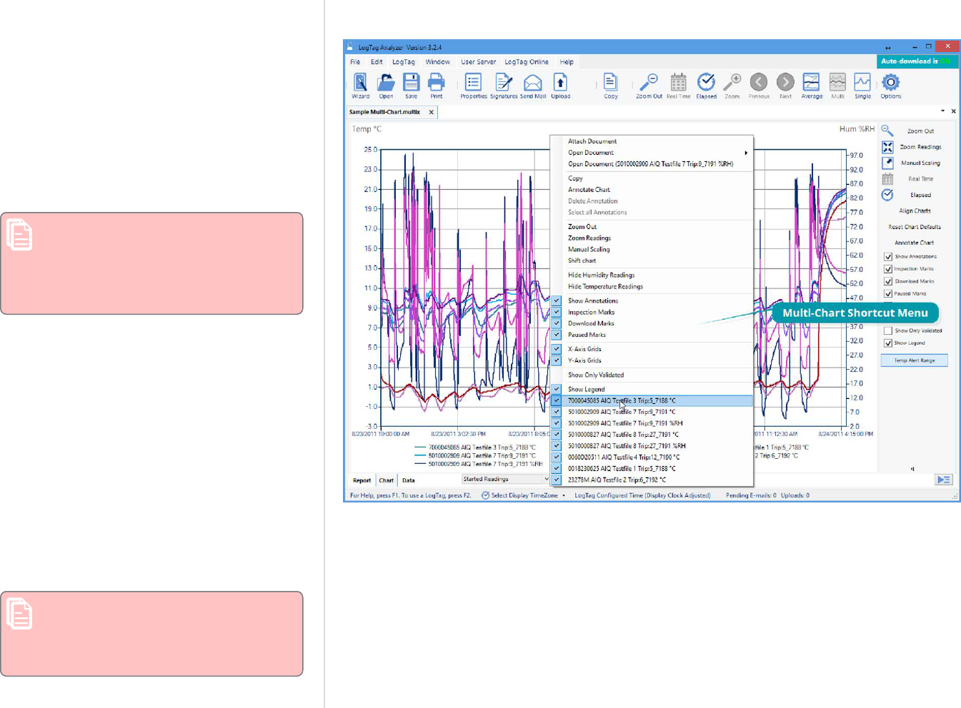
Hiding and Showing Charts
Figure 92: Shortcut Menu after right-clicking on chart area
In the multi chart window you can hide each
chart individually. Right-click anywhere on
the chart, point to the entry of the file you
wish to hide and click to clear the tick. To
show the chart again, repeat the procedure
and select the name again.
You can also hide all humidity readings, or all
temperature readings. A tick will indicate the
readings that are hidden. To show these
readings again, click the entry once more.
Note: If the temperature readings are
hidden, and you click Hide Humidity
Readings, the temperature readings
will be shown and the humidity
readings hidden.
Opening additional files
If you open additional files, these will initially
be shown in separate file window tabs,
including data from freshly downloaded
loggers. You can add the data for these files
to an existing multi chart. Right-click
anywhere on the multi chart and point to
Attach Document. Click the name of the file
you wish to add.
Removing files from the multi chart
If you wish to permanently remove a file from
the multi chart , hide the chart as described
above, then save the file.
Once saved, hidden files will be
permanently removed from this
chart. To prevent data loss, ensure a
copy of the individual file was saved.
Additional Features for TRED30-16R and TRED30-16CP models
LogTag
®
Analyzer User Guide
page 112

More than one multi chart window
If you open at least two additional files, you
can generate a second multi chart by clicking
the multi chart icon from the toolbar. All files
shown in separate windows will be combined
into a new multi chart window. The new multi
chart window additionally contains all charts
from the original multi chart, but they are
initially hidden. They can be shown as
described on the previous page.
The Summary tab is not available in
the multi chart display. If you require
additional information about the
chart data, activate the display of the
desired statistics in the Chart
Statistics section in the Options
Window (Chart Statistics on
page154). The chosen values will be
displayed separately for each chart.
Extracting individual files from a multi chart
A multi chart contains the complete data sets
for each of the loggers from which is was
generated.
You can view the data for each individual
chart in a single-chart window by extracting
them to a *.ltdx file.
Right-click anywhere on the chart, click Open
Document and click the name of the file you
wish to extract. A new file window tab will
open, showing the contents of the extracted
file, which is saved in the same location as
the multi chart.
Additional Features for TRED30-16R and TRED30-16CP models
LogTag
®
Analyzer User Guide
page 113

Aligning Charts
Select Align Charts from the Chart Control Panel to automatically align all charts in the current
multi chart window to the earliest start time:
l
When Started Readings is selected, the charts are aligned so the first started reading is
shown at elapsed time zero. Charts with no Started readings (i.e. charts with only pre-start
readings) are hidden in this view.
l
When Pre-start Readings is selected, all charts with Pre-start readings are aligned so the
earliest Pre-start reading is shown at elapsed time zero. Charts with no pre-start readings
are hidden in this view.
l
When All Readings is selected, all charts are aligned so the earliest reading is shown at
elapsed time zero, regardless whether this is a Pre-start reading or a Started reading.
Every chart is assigned a different color based on the Chart palette and elapsed time is shown.
If you use the toolbar Icon to switch to Real Time, the charts will be shown in their
original relative position.
Shifting Charts
Figure 93: Shifting a chart
For easier data comparison, chart start times can be shifted while you are viewing the multi
chart display.
To shift a chart, move the mouse pointer over the chart until a tooltip from that chart is
displayed. Right-click, then click Shift Chart. A dialog box will be displayed, where the new
start time and date can be selected.
Click the down arrow next to the date to display a calendar where you can select the new start
date. Highlight the hours or minutes from the time and use the up and down arrows next to
the time to change the numbers.
You can revert the chart to its original display by clicking Original start time.
To apply the selected start date and time click OK .
Min/Max/Average Chart Display
When you click the Average icon in the toolbar, the currently active multi chart file tab
will now show charts for the calculated values of minimum, maximum and average readings,
instead of the individual charts.
Switching from Average display to Standard display and vice versa, or changing the Readings
Range will force the multi chart to be re-drawn according to the default settings. You can then
use the standard zoom controls to show the portion of the charts you want to see.
Additional Features for TRED30-16R and TRED30-16CP models
LogTag
®
Analyzer User Guide
page 114

You can annotate the Average Chart in the same way as any other chart tab; such annotations
will be visible in the other chart tabs and are stored with the multi chart when saved. An
annotation that is linked to a data point on the chart will still be shown, even if the data point
itself is no longer being displayed.
Please note the following behavior:
l
Zoom settings will not transfer to the Average tab.
l
Download marks and inspection marks will not be displayed in the "Average" tabs.
l
Non-validated readings and re-calibrated readings will not be displayed with the special
attributes, even if set in the options. If you have chosen to show non-validated readings,
they are included in the minimum/maximum/average calculations, otherwise not.
Figure 94: Warning: Too many charts open
l
To avoid memory overflows, the maximum number of data points or loggers that can be
shown in the average chart is restricted. If you try to show average charts outside these
limits, you will see this warning message:
l
If one or more of the charts have sections with readings outside the LogTag
®
's sensor
range, LogTag Analyzer is unable to calculate the minimum, maximum and average values,
and those sections of the graph will not be displayed. This will likely result in a "broken"
graph line, regardless of whether show readings beyond specifications in the Charts section
in the Options Window is enabled or not (Charts on page155).
l
Due to the large number of calculations performed in this feature, specifically when opening
large numbers of charts spanning long periods, having the Average displayed can occupy
large amounts of memory and run slow. Therefore we recommend only turning the feature
on when required.
Clicking on the Average Icon in the toolbar again will turn the average display off. Selecting the
single charts command in the toolbar will open each chart in the multi chart in a separate File
Window, however the Average Chart tab will not be closed.
Additional Features for TRED30-16R and TRED30-16CP models
LogTag
®
Analyzer User Guide
page 115

Behind The Scenes
Figure 95: Multi chart data - as recorded
To create some meaningful results, LogTag Analyzer uses a special trend line process to
calculate the minimum, maximum and average values across multiple charts, rather than a
histogram. It is important you understand this mechanism, so you can interpret the displayed
readings correctly.
This is an example of two loggers, one with a 5 minute log interval (A) and the other (B)
logging every 2 minutes.
Figure 96: Multi chart data - normalized
Before the data are displayed in an average tab, LogTag Analyzer normalizes every chart's
readings so they fall in line with the logging interval of the LogTag
®
with the shortest log
interval, in this case unit (B). It does not shift any charts, but rather calculates a theoretical
value for those reading times by linear interpolation. Interpolation determines probable
environmental conditions, i.e. what the LogTag
®
would have recorded had it taken a reading at
that time.
Without this method, it would not be possible to compare units with different log intervals, or
those that have the same log interval, but were started at different times.
Figure 97: Multi chart data - normalized min/max/average curves
As a result of this process, absolute values for minimum and maximum may not always be
shown if they do not fall on normalized times, as seen in the example at 10:35 - despite 21 ºC
being the maximum it will not be displayed as it is not a normalized value.
Note: The charts in above example are based on loggers started at the same time. If
unit (A) had been started earlier, depending on the start time unit (B) may also have
its readings interpolated. To ensure the chart with the shortest log interval always has
its real values shown, please use the Aligning Charts function from the context menu.
Additional Features for TRED30-16R and TRED30-16CP models
LogTag
®
Analyzer User Guide
page 116

Dew Point
Theoretical background
At any given temperature, air can contain no more than a certain amount of water vapor before
it is saturated. Relative humidity is one way of describing how much water vapor is currently
present in the air in relation to how much there would be if the air was saturated.
Figure 98: Formula used for dew point
Dp
(T,RH)
Dew point calculated from
relative humidity and
temperature
T
The temperature at the
calculated data point.
RH
The humidity at the calculated
data point.
β
17.62, Sonntag ITS-90
constant
λ
243.12°C, Sonntag ITS-90
constant
Relative humidity is therefore described as a percentage. The higher the temperature, the more
water vapor the air can hold, the lower the temperature, the less.
The dew point is defined as the temperature air needs to cool down to, so it becomes saturated
with moisture. The water vapor then condenses and forms, for example, dew, rain, fog or
snow.
If a foreign body is brought into an environment, and it is colder than the dew point, moisture
will form on the surface of that object.
Knowing dew point and its difference to the current temperature will allow you to assess how
likely it is that condensation will form on the goods or materials you monitor.
Since dew point is closely related to temperature and relative humidity, it can be calculated if
those are known, for example, using a temperature and humidity logger such as the HAXO-8 or
UHADO-16. LogTag Analyzer uses the Magnus formula with the Sonntag ITS-90 constants for
an approximation of the dew point, that does not take into account atmospheric pressure. The
approximation is typically accurate for temperatures between -45 °C and +60 °C, but carries
some small errors, which can be estimated from the chart below. The formula is less accurate
for water vapor over ice.
Additional Features for TRED30-16R and TRED30-16CP models
LogTag
®
Analyzer User Guide
page 117

Figure 99: Approximate dew point error for humidity/temperature
Additional Features for TRED30-16R and TRED30-16CP models
LogTag
®
Analyzer User Guide
page 118
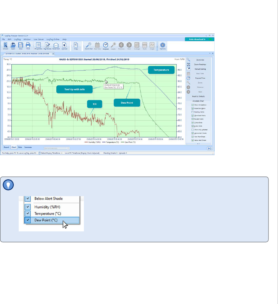
Application
The dew point shows as an extra line on charts for temperature and humidity loggers, such as
the HASO-8, HAXO-8 or UHADO-16.
By default, this feature is disabled. You can enable it in Options in the section about Charts on
page155.
If the dew point line is enabled, you can toggle it off and on by right-clicking
anywhere on the chart and clicking the Dew Point entry:
If the dew point line is disabled, this menu entry is not available.
Dew point lines are not currently supported on multi-charts.
Additional Features for TRED30-16R and TRED30-16CP models
LogTag
®
Analyzer User Guide
page 119

Chart annotations
Figure 100: Chart Right-Click Menu
Figure 101: Chart Annotation Panel
You can include additional information in your chart tab by adding textual and graphical
annotations. Annotations are stored in the *.ltdx file and will be shown again when you next
view the file. Annotations will be printed, and will also be shown on anyone else's computer, if
you are sharing annotated files. You can place up to 58 individual annotations.
If a chart's annotations are currently shown, you can hide them by right-clicking anywhere on
the chart and clearing the tick for Show Annotations. You can show them again by selecting
Show Annotations. You can also perform both actions via the Chart Control Panel.
Adding Annotations
To start annotating charts, right-click anywhere on the chart and select Annotate Chart from
the menu. This will open the basic view of the Annotations Panel.
You can also open this by clicking Annotate Chart from the Chart Control Panel.
When the Annotations Panel is open, an annotation will be placed at the position of the mouse
pointer every time you click the mouse button on the chart canvas. You can choose different
types of annotations with different behavior.
The following table explains what each of the options in the Annotations Panel mean and how
they influence the look and position of the annotation:
Option Selection What it does
Anchor type Chart Point If a Chart Point annotation is placed, the annotation will always be
linked to the time stamp of the reading on which the mouse pointer is
positioned when placing the annotation. If the chart is zoomed or
panned, and the data point is not visible, the annotation is also not
shown. When a chart becomes part of a multi chart, all chart point
annotations for the single chart are also visible in the multi chart.
Chart point annotations are good for marking specific times on the
chart with additional information.
Background If a Background annotation is placed, the annotation will always be
linked to the position on the canvas in which it was placed. Even if the
chart is zoomed or panned, the annotation will always stay in the
relative position from the canvas edges.
Background annotations are good for placing information relating to
the entire chart. The Statistics Information for example is placed on
the canvas using a background annotation.
Table 17: Basic annotation options
Additional Features for TRED30-16R and TRED30-16CP models
LogTag
®
Analyzer User Guide
page 120

Option Selection What it does
Add DataPoint
Information
Enabled
Disabled
This option can only be selected when the Anchor type is Chart Point.
If enabled, text will automatically be added to a callout, showing date,
time, value and type of reading. If disabled, the callout will be empty.
Add Series
Information
Enabled
Disabled
This option can only be selected when the Anchor type is Background.
If enabled, text will automatically be added to a callout, showing the
charts series information from the legend. If disabled, the callout will
be empty.
Type Callout
Rectangle
When this annotation
type is selected, a
rectangular callout shape
is used when placing the
annotation. If the Anchor type is Chart Point, a pointer to the related
reading is also added, To add text or change the automatically placed
text double-click the annotation.
Callout Ellipse When this
annotation
type is
selected, an
elliptical
callout shape
is used when
placing the
annotation. If
the Anchor type is Chart Point, a pointer to the related reading is also
added, To add text or change the automatically placed text double-
click the annotation.
Line When this annotation type is selected,
you can place a line on the drawing
canvas:
l
Move the mouse pointer to where you wish the line to start
l
Press and hold the mouse button
l
Move the mouse pointer to where you wish the line to end
l
Release the button
Additional Features for TRED30-16R and TRED30-16CP models
LogTag
®
Analyzer User Guide
page 121

Option Selection What it does
Arrow When this annotation type is selected from
the drop down, you place an arrow on the
drawing canvas:
l
Move the mouse pointer to where you wish the arrow head to start
l
Press and hold the mouse button
l
Move the mouse pointer to where you wish the arrow tail to end
l
Release the button
Rectangle When this annotation type is
selected from the drop down, a
rectangular shape is placed on the
drawing canvas. This rectangular
area is useful for highlighting
sections of the chart, but please note that you cannot place text inside
this shape.
Chart Statistics This annotation is only available as a Background annotation. When it
is selected from the drop down, a rectangular callout is placed on
drawing canvas, and text will automatically be added to the callout,
showing the information defined in Chart Statistics on page154, for
example range of readings or min/max/average values.
Tip: If you wish to place a rectangle with text inside, place a
Chart Statistic Annotation and replace the text with your
own.
Figure 102: Advanced View of the Annotations Panel
You can refine the appearance of annotations in the advanced view of the Annotations Panel.
This view can be activated by clicking the Advanced button when the Annotations Panel's basic
view is shown.
You can click Basic to return to the basic view. If you close the Annotations Panel while in
advanced view, next time you open it, it will also show the advanced view.
You will be familiar with these options from many other Windows programs:
Group Selection What it does
Style Line width
Line Style
Line Color
Color
Transparency
These parameters define the look of the shape object that is
placed with every annotation. Line width, style and color define
the outline of the object, color determines the object's fill color
and transparency defines how opaque or transparent the object
will be. 100 is equal to the object being fully opaque, 0 to the
object being fully transparent.
Table 18: Appearance settings
Additional Features for TRED30-16R and TRED30-16CP models
LogTag
®
Analyzer User Guide
page 122
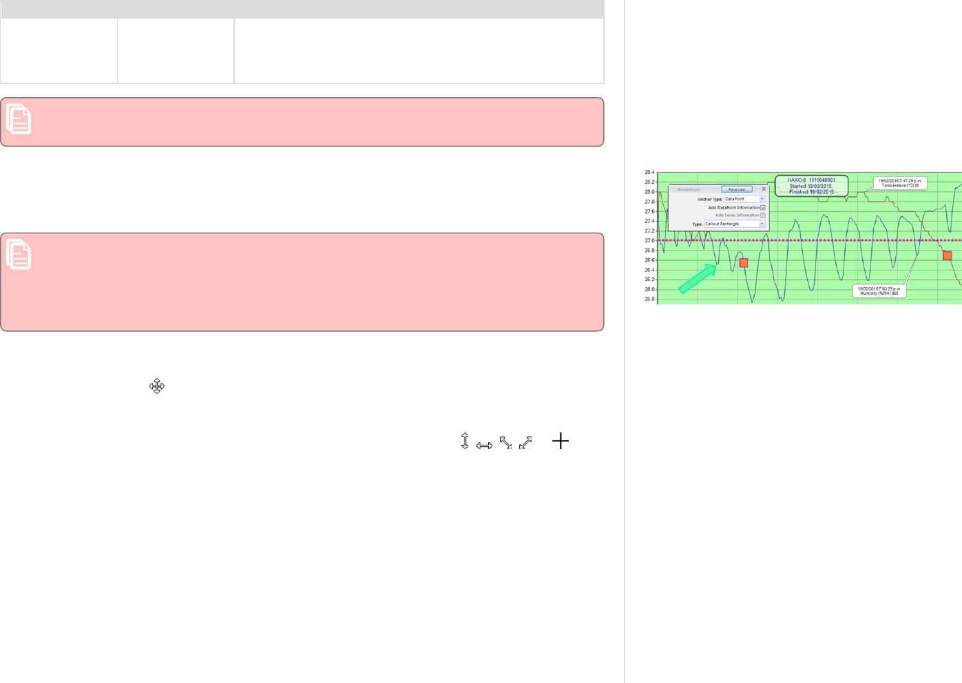
Group Selection What it does
Font
Font Color
Size
Font
Font Style
These parameters define the properties of the font used for text
inside the callouts. Note that only a small selection of system
fonts is available.
Note: Mouse zooming and panning is disabled when making annotations.
You can, however, still use manual scaling to zoom to the desired section of the chart.
Figure 103: Chart with different types of annotations
To stop annotating the file, close the Annotations Panel; right-click anywhere on the chart and
select Annotate Chart from the menu. You can also close it by clicking Annotate Chart from the
Chart Control Panel or by clicking the Annotations Panel's Close button . If you change file
window tabs, the Annotations Panel closes automatically.
Chart annotations added in the chart tab will also show in the chart displayed at the
bottom of the Report Display on the next page, which is much smaller. If you want the
text to remain legible in the Report tab, you may need to choose a larger font and
increase the size of the surrounding frame to suit. If you intend to print the Report we
recommend you trial a suitable size for the font using the advanced view.
Editing Annotations
To change the position of an annotation, use the mouse and point to the annotation. When the
pointer has changed to , press and hold the mouse button, move the annotation to the
desired location and release the button.
To change the size of an annotation, click inside the annotation. The sizing handles appear.
Use the mouse and point to one of the handles until the cursor changes ( , , , or ).
Press and hold the mouse button and drag the handle to the desired size.
To edit the text of an annotation, double click the annotation.
Deleting Annotations
To delete an annotation, click inside the annotation and press the Delete key. You can also
right-click inside the annotation and click Delete Annotation.
Additional Features for TRED30-16R and TRED30-16CP models
LogTag
®
Analyzer User Guide
page 123
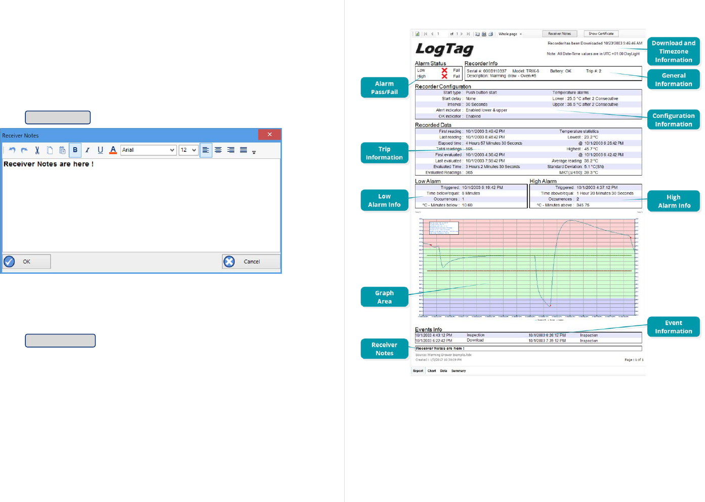
Report Display
Figure 104: Report Tab
The Report display tab provides a convenient and quick way of seeing
all important information for a trip in one single screen.
The graph area shows the same chart segment as the one you see in
the chart tab. The zoom controls do not work in the report tab, so if
you wish to show only a particular segment, you need to zoom to this
segment in the chart tab before viewing the report. Annotations are
visible, but the chart cannot be annotated when in the Report Tab.
Click Receiver Notes to open a window where you can add text:
Figure 105: Receiver Notes Entry Dialogue
This text is stored in the file, and displayed in the report's Receiver
Notes section every time the file is opened. Use the dialogue toolbar's
controls to format the text.
Click Show Certificate to display a window with the logger's factory
calibration certificate (if available). See Calibration Certificates on
page89
The Events Info section lists all events that have taken place during
the trip. You will see if a logger has been previously downloaded ,
when an inspection mark was placed, when readings were paused or
when the clock was manually changed on a logger with a display.
If a probe was changed during the time shown in the chart, a Probe
Change event will be shown in this list, if either the removed or the
added probe was a Smart Probe.
Additional Features for TRED30-16R and TRED30-16CP models
LogTag
®
Analyzer User Guide
page 124
You will also see an entry for each time a digital signature was applied
to the file, together with information which signature was applied by
which user.
For each block of paused readings in USB loggers only the first
and last reading are listed.
Additional Features for TRED30-16R and TRED30-16CP models
LogTag
®
Analyzer User Guide
page 125

Multi Chart Reports
A multi chart can also be viewed in the report tab, where you can see a
brief summary for each logger, a and a smaller version of the chart.
Chart annotations added here will also show in the chart that is
displayed at the bottom of the Report Display on page124, which is
much smaller that the one in the chart tab. If you want the text to
remain legible in the Report tab, you may need to choose a larger font
and increase the size of the surrounding frame to suit. The report also
shows a summary for the combined data of all loggers that make up
the multi chart, separately for all readings and the zoomed readings.
Additional Features for TRED30-16R and TRED30-16CP models
LogTag
®
Analyzer User Guide
page 126

Data Display
Figure 106: Data tab
When you click the data tab, the readings are displayed in a
spreadsheet-like list in chronological order, including an index, date &
time and elapsed time.
The data tab only displays those readings shown on the chart. If the
chart is zoomed in, the data tab only shows those zoomed readings.
You cannot use the scroll bar or arrow keys to display readings before
or after the currently zoomed readings; to expand the number of
readings switch to the chart and zoom out.
For temperature and humidity loggers such as HASO-8, HAXO-8 or
UHADO-16 the humidity values will be displayed in their own column,
so will dew point values if this feature is enabled.
On the list you can also identify any special marks attached to the
reading, such as download marks (identified through rose
background), inspection marks (identified through red background),
paused marks (identified through blue background) and min/max reset
marks (identified through green background). The text color identifies
if a reading has been above the upper alert value (red), below the
lower alert value (blue) or within specification (black). You can scroll
through the readings with the arrow, page up/down, home and end
keys, or use the mouse wheel.
You can sort the list by clicking one of the column headers. This can
be useful, for example, when you want to look at all events and the
times they occurred.
You can add a comment for each reading. This comment will be stored
against the reading when you save the file. In the row for which you
wish to add a comment, click in the Comment column and type your
text.
The list grid can be copied to the Windows clipboard and pasted into
other windows applications such as Excel. Press CTRL-C to copy the
entire currently displayed list. Copied data always include the header
row, even if it is not highlighted, and are always sorted by index. You
can also click Copy from the Edit menu, or right-click in a row and
click Copy All. You can also copy only the highlighted rows if you
Additional Features for TRED30-16R and TRED30-16CP models
LogTag
®
Analyzer User Guide
page 127

right-click anywhere in the highlighted section and click Copy
Selected. You can select as many rows as you wish using the mouse.
Point to the first row you want to select. Press and hold the mouse
button, drag the pointer to the last row you wish to select, and release
the button.
Additional Features for TRED30-16R and TRED30-16CP models
LogTag
®
Analyzer User Guide
page 128

Multi Chart Data Tab
Figure 107: Multi chart data tab
Data listings are also available when viewing a
multi chart. Here, the data listings for the
individual loggers are combined into a single
list, with each row representing one reading
from a single logger.
Marks, text and background colors are shown
in the same way as for single file lists.
Readings are initially sorted and indexed
chronologically, but can be sorted by clicking
one of the column headers. This can be
useful, for example, when you want to look at
all readings from a specific logger. If you wish
to return to the original chronological sort
order, simply click the Index column header.
You can add a comment for each reading. This
comment will be stored against the reading
when you save the file. In the row for which
you wish to add a comment, click in the
Comment column and type your text. Copy
and Paste functions work identical to the
single file data tab.
If you combine more than 10 charts
into a multi chart, the data tab is not
available. Dew point readings are not
shown in the multi chart data tab.
Additional Features for TRED30-16R and TRED30-16CP models
LogTag
®
Analyzer User Guide
page 129

Figure 109: Statistics tab with summary for all readings
Summary Display
The summary tab offers a brief statistics overview of some of the important trip data. You can
customize the statistical data you wish to include in this tab in the Options dialogue for the
Summary Statistics on page152.
The first section shows the data for the complete trip, regardless of whether or not the chart is
zoomed in. The second section is only displayed if the chart is zoomed in, and displays the
statistics for only the zoomed readings.
If there are readings beyond the limits of the sensor within the time interval displayed, the
statistics for this interval will show "**".
The zoom controls available for the chart tab are inactive in the summary tab.
Figure 110: Statistics tab when inspection marks are included
If inspection marks are present in the data, statistics summaries for each of the inspection
mark groups in the data can be seen amended to the end.
The list grid can be copied to the Windows clipboard and pasted into other windows
applications such as spreadsheets, including the list header row.
Displaying statistics
The statistics displayed on the Summary tab can be configured in the Options dialog. Refer to
the topic on Summary Statistics on page152. By default, all statistics are displayed on the
Summary tab.
For temperature and humidity loggers two additional statistics are automatically shown when
the dew point feature is enabled:
l
Dew point offset range
The dew point offset is the difference between the temperature and the calculated dew
point. The closer this offset gets to 0, the closer the temperature is to the dew point. The
dewpoint offset range is a measure of how close the dew point got to the actual temperature
during the trip.
l
Average dew point offset
The average dew point offset for the recorded data.
Statistics can also be displayed on the chart, in a Chart Statistics Annotation. Refer to the topic
on Chart Statistics on page154 for more information about configuring the chart statistics.
If there are readings beyond the limits of the sensor within the time interval being displayed,
the statistics for the relevant interval will be displayed as "**".
Additional Features for TRED30-16R and TRED30-16CP models
LogTag
®
Analyzer User Guide
page 130

Day Summary Display
The day summary tab is displayed for
LogTag
®
models with an integrated statistics
memory.
LogTag
®
logger products with display
Figure 111: Day summary for loggers with display and
statistics memory
For these logger models the day summary
display shows the history of up to 30 days,
arranged into 24 hour periods, with
information about maximum and minimum
values for the day, and if alarms have been
triggered on those days.
The Day summary grid can be copied to the
Windows clipboard and pasted into other
windows applications such as spreadsheets,
including the header row.
Additional Features for TRED30-16R and TRED30-16CP models
LogTag
®
Analyzer User Guide
page 131

Printing the results
Figure 112: Page Setup Window
Printing from LogTag Analyzer is similar to printing from other
Windows software.
Before you print for the first time, however, we suggest you take some
time to set-up your preferred page settings.
Page Setup
Click Page Setup from the File menu; the Page Setup window will be
displayed.
You can set page margins, paper size and orientation. You can check
what the print will look like by clicking Print Preview from the File
menu, as described on page42.
Figure 113: Printer dialogue
Printing a single document
Click the Print icon ( ) on the toolbar or click Print from the File
menu to display the Print window.
Choose a printer and, if required, adjust its properties.
Choose the range of pages to be printed:
l
All - All pages will be printed
l
Selection - Prints the range of readings you selected, for example
by highlighting rows in the data tab.
l
Current page - Prints only the current page.
l
Pages - Prints only the pages you specify in the text entry.
Please note that LogTag Analyzer will try to print charts and reports
on a single page where possible.
Printing multiple documents
You can print all currently open documents at once.
Click Print All from the File menu; the printer dialogue will be
displayed. After you have made your selection click print, and each
document's currently active tab will be printed with the respective
zoom settings.
Additional Features for TRED30-16R and TRED30-16CP models
LogTag
®
Analyzer User Guide
page 132

Printing multiple documents on high-resolution monitors can make
your computer unresponsive for long times. We recommend to print
no more than three documents at the same time.
Additional Features for TRED30-16R and TRED30-16CP models
LogTag
®
Analyzer User Guide
page 133

Automatically calculated statistics
When displayed recorded data, the software will automatically calculate and display some
statistics calculated from those data. These statistics are shown on the summary tab and are
also calculated for each sequence of data points between the inspection marks.
If any readings within the time interval are beyond the limits of the sensor, the values for
Average Reading, Standard Deviation, and Mean Kinetic Temperature will not be displayed for
the relevant time interval .
Average Reading
Figure 114: Formula for average reading
av
is the calculated arithmetic mean
n
is the number of data points to include in
the calculation
t
i
are the sequence of data points to include in
the calculation
The Average Reading is the arithmetic mean of the sequence of data points. It is calculated by
adding all the data point values together and then dividing the total by the number of data
points. Mathematically this formula can be expressed as illustrated.
For example, if there were 5 data points to calculate the arithmetic mean of and they were,
12.3, 15.9, 16.2, 14.7, 14.9, then the arithmetic mean would be 14.8.
The number of decimal places displayed can be set to 1, 2 or 3 by clicking Options from the Edit
Menu, then navigating to the Summary Statistic section and selecting the number of decimal
places from the Decimal Places entry. Please note this setting is shared amongst all statistics
calculations.
Additional Features for TRED30-16R and TRED30-16CP models
LogTag
®
Analyzer User Guide
page 134

Degree Minutes
Figure 115: Formula for degree minutes
deg min
Total Degree Minutes spent
above/below the alert
threshold.
ti
The temperature that was
above/below the alert
threshold.
a
The alert temperature
threshold.
s
The duration of time, in
minutes, the temperature was
sustained.
Some products and materials change their characteristics or degrade, if they are exposed to
temperatures outside the ideal conditions for extended periods. For example, some products
may experience freezer burn if they experience an extremely cold condition or experience a
colder than ideal temperature for a long period of time. LogTag Analyzer will automatically
display the results of two separate Degree Minutes calculations. The result of the first is based
on the readings recorded below the "ideal conditions", the second on the readings above the
"ideal conditions". The "ideal conditions" used in the calculation of the Degree Minutes
formula are represented by the non-alert range based on the upper and lower alert values
entered during configuration of the LogTag
®
.
Mathematically the formula for calculating the degree minutes above alert can be expressed as
illustrated.
For example, if there were 5 data points to calculate the degree minutes of and they were, 12.3,
15.9, 16.2, 14.7 and 14.9 degrees, each of these temperatures were recorded at 2 minute
intervals and the high alert temperature threshold was 12.6 degrees, then the degree minutes
temperature above the upper alert threshold would be 22.6 degree-minutes.
Additional Features for TRED30-16R and TRED30-16CP models
LogTag
®
Analyzer User Guide
page 135

Mean Kinetic Temperature
Figure 116: Formula for mean kinetic temperature
mkt
is the mean kinetic
temperature, in degrees
Celsius
ΔH
is the activation energy.
R
is the universal gas constant,
which is 0.0083144 KJ/mol K
n
is the number of data points
to include in the calculation
t
i
represents the data points to
include in the calculation, in
degrees Celsius
Some products and materials have accelerated rates of degradation at higher temperatures. For
example, perishable food items and pharmaceutical products can degrade and many forms of
bacteria grow exponentially as the environmental temperature increases. Mean kinetic
temperature is a calculation that accommodates the non-linear thermal effect, which
temperature can have on products. Mean kinetic temperature is represented as the equivalent
temperature the product was thermally subjected to during the time the various temperature
readings were recorded.
Mathematically the formula for calculating the mean kinetic temperature can be expressed as
illustrated.
For example, if there were 5 data points of which to calculate the mean kinetic temperature,
they were, 12.3, 15.9, 16.2, 14.7 and 14.9 degrees Celsius, then the mean kinetic temperature
would be 14.9 degrees Celsius using the default
ΔH
.
By default LogTag Analyzer uses an activation energy value of 83.144 KJ/mol for the calculation.
To enter a custom value for
ΔH
, click Options from the Edit Menu, then navigate to the
Summary Statistic section where you can enter the desired value in the Use the following value
text field.
Charts and the Statistics page display the
ΔH
parameter if it is different to the default value,
and display Logger deltaH if the parameter from the logger was used.
Additional Features for TRED30-16R and TRED30-16CP models
LogTag
®
Analyzer User Guide
page 136

Standard Deviation
Figure 117: Sample based standard deviation
Figure 118: Population based standard deviation
s
the calculated sample based
standard deviation
sN
the calculated population
based standard deviation
n
the number of readings to
include in the calculation
av
the calculated arithmetic
mean
t
i
a reading to include in the
calculation
The standard deviation is a useful measure for determining how spread out the readings are
from the arithmetic mean (Average Reading). Most controlled environments typically try to
keep the environmental conditions at a stable and consistent humidity and/or temperature.
The standard deviation can be used to help indicate how stable the environmental conditions
were maintained. One standard deviation (sometimes expressed as "one sigma") away from the
mean, positive or negative represents approximately 68 percent of all the readings. Two
standard deviations, or two sigmas, away from the mean represents approximately 95 percent
of the readings. Three standard deviations represent about 99 percent of the readings.
For example, if the arithmetic mean of the readings was 50.6 °C and the standard deviation was
2.3 °C, then approximately 68% of the readings were between 48.3 °C and 52.9 °C, 95% of all the
readings were between 46.0 °C and 55.2 °C and 99% of the readings were between 43.7 °C and
57.5 °C. Further more, if all the readings were recorded over a span of 1 day (24 hours) then the
temperature was between 48.3 °C and 52.9 °C for approximately 16 hours and 19 minutes during
the recorded period of time.
Mathematically standard deviation can be expressed as illustrated.
LogTag Analyzer allows the calculation of sample or population based standard deviation.
Which of those is used for the calculation can be set by clicking Options from the Edit Menu,
then navigating to the Summary Statistic section and selecting sample based or population
based.
Here you can also adjust the number of decimal places used to display the result, but please
note this setting is shared amongst all statistics calculations.
For a more detailed explanation of the various ways to calculate standard deviation please
consult the relevant literature related to statistical and probability calculations.
Additional Features for TRED30-16R and TRED30-16CP models
LogTag
®
Analyzer User Guide
page 137

Sharing recorded data with others
You can share data downloaded from a LogTag
®
device with other users in a number of
different ways.
l
If the person you wish to share the data with has access to the same software version of
LogTag Analyzer as you, you can send the latest *.ltdx file via email, or upload it to an FTP
server.
You can find more details about sending files automatically or upon request in the sections
about Automatic emailing and uploading to FTP sites on the next page and Sending a file by
email directly from LogTag Analyzer below
l
If they have an earlier copy of LogTag Analyzer prior to version 3, it may be easier for them
if you send a legacy file, such as the *.ltd format. You can use the Save As function, then
send the file manually via the Send Mail function.
l
If the other user does not have access to a version of LogTag Analyzer, you can send the data
in various export formats, such as spreadsheet files, PDF files and various other text format
files. You can find the relevant information in the sections about Saving a file for use in
spreadsheets on page140, saving Exports and Reports on page179
l
If you have access to LogTag
®
Online you can upload the data to your account, and add the
other person to your team. See Integrating LogTag Analyzer with LogTag Online on
page143for more information.
Sending a file by email directly from LogTag Analyzer
You can email files to someone else directly from inside LogTag Analyzer.
Figure 119: Send Mail Toolbar Icon
When you click the Send Mail icon from the toolbar, a new email message will be created in
your default email program, with the currently active file already attached to the message. Type
the recipient's email address, add a message that you wish to include and then click Send.
Clicking on Send in the File menu will achieve the same results as clicking the Send Mail icon.
Note, the recipient of the file will need to have LogTag Analyzer software installed to open and
view the file you sent. LogTag Analyzer software is free and can be downloaded from
https://logtagrecorders.com/software/lta3/download/.
If you want to send data in file formats other than the LogTag Analyzer format, specify the
desired file formats in the Exports and Reports section in the Options Window (Exports and
Reports on page179). The data files will automatically be attached to your emails in the desired
formats.
Additional Features for TRED30-16R and TRED30-16CP models
LogTag
®
Analyzer User Guide
page 138

To send a multi chart, it must first be saved to disk (Saving a Multi Chart File on page99).
Note: You can automatically send emails and upload files to ftp sites using LogTag
Analyzer's automated SMTP and FTP functionality. Please see Automatic emailing and
uploading to FTP sites below for further details.
Automatic emailing and uploading to FTP sites
Every time data are downloaded from a LogTag
®
, LogTag Analyzer can automatically email the
resulting data files to pre-selected recipients or upload them to an FTP site.
Email uses SMTP (Simple Mail Transfer Protocol), which defines how electronic mail is
distributed across networks.
FTP (File Transfer Protocol) describes a mechanism by which files are transferred between
different computers and networks.
LogTag Analyzer supports different authentication methods for each protocol, which you can
select when you configure the settings for each service. Here, you also set whether the process
should be automatic, on request, or both.
If you wish to learn more about FTP, SMTP, email and networking please refer to one of the
many good articles available on the Internet, such as the ones on Wikipedia or the various FTP
and SMTP client providers.
If you activate manual uploading/emailing, but not automatic uploading/emailing, you need to
click the Upload button on the toolbar to upload or send the file in the currently active window.
Figure 120: Active and inactive Upload Toolbar Icon
If the button is inactive, neither email nor FTP options are enabled.
When uploading or emailing files this will be shown in the status bar Upload Status on page44.
Tip: The manual email function described here is different from the "send mail"
button on the toolbar. The Send mail button opens a draft message in your standard
email program and attaches the data file. You then need to complete the recipients'
email addresses and press the send button. The manual email function via SMTP does
not use your standard email program, but the configured SMTP settings and requires
no further action once the Upload button on the toolbar is clicked. You can, however,
not change the recipient without changing the SMTP settings.
Additional Features for TRED30-16R and TRED30-16CP models
LogTag
®
Analyzer User Guide
page 139

Note: The automatic functions only work if a file is created by downloading data from a
LogTag
®
in the interface. If the uniqueness settings in the File and Folder Settings are
set so that certain conditions do not result in creation of a new file, no file is uploaded
or emailed either. If you always want to upload a file, we suggest you add the file
creation time variable (%TIME) to the file name, that way a new file will always be
generated .
Note: If you upload a file via the manual or automatic FTP function, any file that
already exists on the server with the same name will be overwritten without warning.
It is up to you to make sure files are created with unique file names.
Saving a file for use in spreadsheets
Occasionally you may wish to export a LogTag
®
data file so you can analyze it in more detail
using a spreadsheet program such as Microsoft™ Excel. You can choose between a few different
options to achieve this.
CSV File export
You can use the File - Save as command from the menu, and select the *.csv option. CSV files
can be read by most spreadsheet programs and text editors. CSV files are the most flexible
export files, as they can be customized in Exports and Reports to suit your particular export
needs.
The *.CSV file contains a section at the top with a summary of the recorded data, followed by
the list of readings. You can also decide to include index, date, time, elapsed time, events and
comments when you customize the export. You can also choose the day summary for loggers
containing such a summary.
Please note that files created by LogTag Analyzer may not always be true CSV files (
Comma Separated Values), as they use the list separator from the Windows operating
system. It does however mean the file can be opened with MS Excel without going
through the data import facility. To create a true CSV file select "Use custom list
separator" and enter a comma in the adjacent field. You can also use the custom list
separator to generate files for applications which require other list separator
characters.
You can also automatically export the data into a CSV file when a logger is downloaded. Please
Exports and Reports on page179 for further details.
Additional Features for TRED30-16R and TRED30-16CP models
LogTag
®
Analyzer User Guide
page 140

LogTag North America Inc also offer a conversion program, which you can use to bulk convert
legacy *.ltd files to *.csv files. You can download this utility called LogTag
®
Convert
from the
software download page at https://logtagrecorders.com/software/.
XLS file export
You can use the File - Save as command from the menu, and select the *.xls option. This
creates a file that can be opened directly with MS Excel. It contains two tabs, one with a listing
of the readings, including index, date, time, elapsed time, events and comments, the second
with the contents of the summary tab. Files from loggers with a day summary will contain a
third tab showing that summary.
XLS files cannot be customized or exported automatically.
Using the Windows Clipboard
Select the Data tab and press CTRL-C or click Edit - Copy from the menu. Open an empty
worksheet in your spreadsheet program and select CTRL-V or click Edit - Paste from the
application’s menu. The data will be pasted in the cells and you can save the file in the format
of your spreadsheet program.
PDF files
Figure 121: PDF Export Settings
LogTag Analyzer can save the currently active LogTag
®
file to a PDF file. One single file will be
generated, which contains the report, chart images, summaries and a data list.
PDF files can be generated automatically, or by selecting Save as from the File menu. Select a
file name and location for your PDF file. Automatic generation of PDF files is enabled in the
section about Exports and Reports on page179. Here you can also define the composition of the
PDF file.
Click the Customize PDF button; the PDF Export Settings dialogue is displayed, allowing you to
select which content of the PDF file will be created.
Note: The report page is always included in the PDF.
If a chart is zoomed, the PDF file will also contain a zoomed setting.
Saving a file as text
Occasionally you may wish to export a LogTag
®
data file so you can import it into other
software as text. You can either do this manually using Save as from the File menu, or
automatically when you download a logger.
You can choose between different text formats:
Additional Features for TRED30-16R and TRED30-16CP models
LogTag
®
Analyzer User Guide
page 141

l
You can save the file as a *.txt file.
This file is a tab delimited file that can be opened in any text editor on a PC.
l
You can save the file as a *.txtm file.
This file is a tab delimited file that can be opened in any text editor on a Mac.
l
You can save the file as a *.html file.
This file is a mark-up text file that can be opened in any browser.
You can define the contents of these files by clicking Options from the Edit menu and selecting
the Exports and Reports tab.
LogTag
®
Data files (*.ltd)
The legacy file type *.ltd is the main file format of LogTag Analyzer software before version 3
was introduced.
You can open these files with LogTag Analyzer version 3 without loss of information.
Annotations, chart titles and receiver notes will all be converted and visible when saved using
the new *.ltdx format.
You can also save data in the *.ltd format using LogTag Analyzer version 3, so they can be
accessed by LogTag Analyzer version 2 or earlier. However, none of the additional settings such
as annotations, zoom and notes are saved.
You can decide which file format you want to be the default format in File and Folder Settings
on page171.
Additional Features for TRED30-16R and TRED30-16CP models
LogTag
®
Analyzer User Guide
page 142

LogTag
®
Online is a web based storage, analysis and sharing portal for data recorded by
LogTag's range of data logging products. You can upload complete trips or live temperature
data recorded from loggers, associate the data with locations and share them with members of
a collaboration team.
What LogTag
®
Online can do is described in detail on the Help Center web page at
https://logtagonline.com/support.
The following section shows the integration of LogTag Analyzer with LogTag
®
Drive, one of the
features of LogTag
®
Online:
l
Signing in on the next page and out of your LogTag
®
Online account
l
Automatically uploading files to LogTag® Online on page145 Drive from Analyzer
l
Uploading data to LogTag
®
Online locations
l
Opening files directly from LogTag® Drive using Analyzer
l
Working with multiple teams on the next page
You can automate some of these steps in the LogTag
®
Online settings.
Note: To maintain compliance with the FDA CFR 21 Part 11 guidelines, you cannot
connect to LogTag
®
Online while being connected to User Server and vice versa. These
options are mutually exclusive.
Additional Features for TRED30-16R and TRED30-16CP models
LogTag
®
Analyzer User Guide
page 143
Integrating LogTag Analyzer with LogTag Online

To upload data to LogTag
®
Online you must be able to access an active LogTag
®
Online account
and connect LogTag Analyzer to your LogTag
®
Online account by entering the sign in
credentials for that account.
Figure 122: Sign in window
You can create a new LogTag
®
Online account by clicking Create an Account in the
LogTag Online menu, which will open a browser window. Complete the details and
follow the on-screen instructions.
Initially, a red dot shows next to the LogTag Online menu, indicating that you are not signed
in. Click Sign In from that menu, and a window opens where you can enter your details:
Provide the email and password for your LogTag
®
Online account and click OK.
Once you are connected, the dot next to the LogTag Online menu changes to green, indicating
that you are now signed in.
In the settings for LogTag
®
Online you can choose to complete the sign in process
automatically next time you start LogTag Analyzer. You can also choose to sign in manually
every time you start LogTag Analyzer.
Working with multiple teams
Figure 123: Team selection for your account
LogTag
®
Online allows you to be part of multiple teams, but you can only upload or view files
for one team at a time. If you are part of multiple teams, you need to select which of these
teams you wish to be the currently active team.
Click Current team from the LogTag Online menu and click the name of the team you wish to
be active.
Now, when you upload files to LogTag
®
Online they will be uploaded to this team, and only
this team's data files are available for opening.
If you are a member of only a single team, this will automatically be selected.
Additional Features for TRED30-16R and TRED30-16CP models
LogTag
®
Analyzer User Guide
page 144
Signing in

If you have a LogTag
®
Online account you can upload data from your loggers directly to
LogTag
®
Online, using LogTag Analyzer. This is useful if you wish to share data online with
others who do not have access to a PC with LogTag Analyzer.
This feature is enabled in the LogTag
®
Online section of the Option settings. If enabled, the
data for each LogTag
®
product you download to your PC is uploaded automatically to your
team's account, provided you are signed in (The LogTag menu shows a green dot). Loggers you
upload are automatically registered as a device in your team's account.
The logger's data are always stored locally in the folder defined in File and Folder
Settings on page171.
Data is, however, only uploaded if a new file is generated when the logger is
downloaded. If no new file is generated, for example when downloading a logger that
has stopped, for a second time, no data is uploaded.
Note that you can only upload the data at the time it is downloaded from the logger. At
the moment, it is not possible to upload files manually.
If your logger is attached to a location
If your logger is attached to a location, the logger's data are added to the location data each
time you download it via LogTag Analyzer.
You can attach all logger models to a location
2
, including USB loggers.
If your logger is not attached to a location
If your logger is not attached to a location, a data file will be uploaded to LogTag
®
Drive in
addition to being stored locally on your PC. This can be viewed in LogTag
®
Online in the same
way as a file uploaded via one of the wireless interfaces (LTI-WIFI or LTI-WM-WIFI). Other
team members can then download the file and view it in LogTag Analyzer.
2
Attaching a logger to a location is done in LogTag
®
Online or via the WiFi wizard. For more information about locations please see the
LogTag
®
Online help.
Additional Features for TRED30-16R and TRED30-16CP models
LogTag
®
Analyzer User Guide
page 145
Automatically uploading files to LogTag
®
Online

If LogTag
®
Online is not available
Figure 124: Sign-in reminder
If LogTag
®
Online is not available at the time you download the logger, for example when the
network is down or you are not logged in, LogTag Analyzer will keep trying to upload the file at
regular intervals, if this is set up in Options - LogTag
®
Online.
You will receive regular reminders to complete the sign-in process.
Opening files directly from LogTag
®
Drive
When you are signed in to your LogTag
®
Online account from LogTag Analyzer, you can open
data files stored in LogTag
®
Drive directly. Click Open from the File menu, or click the Open
toolbar icon.
The folder list contains an Analyzer entry (similar to your Dropbox or Onedrive entries),
showing the currently selected local storage folder as well as an entry LogTagOnline.
Click LogTagOnline to show a list of files currently stored in your LogTag
®
Online account.
These files represent shortcuts to the actual file content stored in LogTag
®
Drive. Once you
have selected a file for opening, it will be copied to your local storage folder, then opened in
LogTag Analyzer in the same way you would open a locally stored file.
Any file you open will be copied to your local storage folder, regardless of the settings
made in Automation. This means the file will be available even after you have signed
out from your LogTag
®
Online account. The shortcut in the Select recent File menu
will reference the local file.
Additional Features for TRED30-16R and TRED30-16CP models
LogTag
®
Analyzer User Guide
page 146

Chapter 4
Customizing the Software
This chapter explains in detail how to customize the software to your needs.
General Settings 149
Summary Statistics 152
Chart Statistics 154
Charts 155
Automation 160
File and Folder Settings 171
Exports and Reports 179
Date and Time Format 182
Communication Ports 185
User Server 186
Activity Logs 188
LogTag® Online 190
Importing and Exporting Option Settings 191

Figure 125: Edit Options Menu
Many of LogTag Analyzer's features can be customized to suit your specific requirements.
This is done in the Options dialogue, which you can open by clicking the Options icon in the
toolbar or by clicking Options from the Edit menu.
Figure 126: Toolbar Icon
To change any of the options, select the corresponding category in the left pane of the options
window. You will the see what can be changed in the right pane. Most of the options available
will be applied as soon as you click OK. For example, if the language selection or the date
format are changed, all windows that are open will be updated without the need to restart the
software.
Some of the display settings, such as decimal point and date/time formats, are
controlled by the regional settings of the Windows operating system. These can usually
be found in the Control Panel under "Regional and Language Options". Please refer to
your Operating System's documentation for further assistance.
Customising the software
LogTag
®
Analyzer User Guide
page 148

General Settings
Figure 127: General settings
The General Settings options allow you to change various preferences that will effect the
overall appearance of the information shown by LogTag Analyzer.
Show temperatures in...
Here you set the unit used for temperature values displayed in the software's dialogues, lists,
charts and reports. The options are:
l
Fahrenheit (°F)
l
Celsius (°C)
l
Kelvin (K)
For loggers with a display and USB PDF loggers the temperature unit used on the
display or in the PDF is set during configuration. It is independent of the temperature
unit chosen here.
Note that if your Windows Region is set to Japan, you will not be able to select
Fahrenheit as your temperature unit.
Default time interval to display
Here you set the default time zoom level. This is zoom is applied when a file is opened or a
logger is downloaded. You can set this to:
l
All readings
l
From first reading to first inspection/download mark
l
From last inspection/download mark to last reading
l
From last inspection mark to last reading
l
From last download mark to last reading
The section about Inspection and download mark zoom on page109 explains in more detail
how this feature works.
Language
This setting determines which language the software uses. Supported languages are:
Customising the software
LogTag
®
Analyzer User Guide
page 149

l
English US
l
Chinese (Simplified)
l
French
l
German
l
Italian
l
Japanese
l
Portuguese
l
Russian
l
Spanish
l
Turkish
Enable automatic checking for a newer version
Figure 128: A software update is available
The LogTag Analyzer software can periodically check to determine if a newer version is
available for download from the LogTag North America Inc website.
To enable this feature select Enable automatic checking for newer version and set the number
of days between checks by entering or selecting a number in "Check every XX days". To disable
the feature, clear the box.
If you enable the automatic check, and a new version is available, a window with an overview
of the update will be displayed. Please see Upgrading LogTag Analyzer on page24
Enable USB Logger Update Check
If you enable this feature, the LogTag Analyzer software will check the LogTag North America
Inc website for available updates that can be applied to USB loggers, at the same time it checks
for a newer version of the software. If updates are available, the required files are downloaded
immediately and offered during the configuration process of any USB loggers that are eligible
for an update. You still have the option of declining the update at the time the configuration
process takes place. Typically, these updates are mandatory or recommended, particularly if
they improve the performance of the unit or add more features.
If you disable this feature, upgrade files are not downloaded or applied.
Optional Updates
Sometimes these updates are entirely optional, because they may impact how -if at all- the
product will work with earlier version of LogTag Analyzer. If you enable the check for optional
updates, these will be offered during configuration just as if they were a mandatory or
recommended update, but the feature will automatically be disabled once you restart LogTag
Analyzer the next time.
Customising the software
LogTag
®
Analyzer User Guide
page 150

Note: Optional updates will always be downloaded when you check the internet for
updates, regardless of this setting. Enabling this feature will only affect if this is
offered during configuration or not.
If you know there is an optional update, and you have enabled this feature, but no
update is offered, please do a manual update check via Help - Check internet for
update, then enable this feature again in the options, then configure your logger again.
This will ensure the required file is available.
Customising the software
LogTag
®
Analyzer User Guide
page 151

Summary Statistics
Figure 129: Statistics Options dialogue
This option allows you to specify which statistics are displayed in the Summary tab.
Automatically calculate and display following data
Select all options you wish to be shown, and clear all options you wish to hide.
What is enabled What LogTag Analyzer shows
Elapsed time The time between the first reading and the last reading of the
recorded data.
Reading range The lowest and highest reading of the recorded data.
Average reading The average reading of the recorded data. Please see
Average
Reading
Degree Minutes below lower
alert
The below degree minutes reading of the recorded data. Please
see
Degree Minutes on page135
for details on how this is
calculated.
Degree Minutes above upper
alert
The above degree minutes reading of the recorded data. Please
see
Degree Minutes on page135
for details on how this is
calculated.
Mean Kinetic Temperature The Mean Kinetic Temperature of the recorded data. Please see
Mean Kinetic Temperature on page136
for details on how this
is calculated.
Time below/equal lower alert The total time of all readings below or equal to the primary
lower alarm threshold.
Time above/equal upper alert The total time of all readings above or equal to the primary
upper alarm threshold.
Time not in alert The total time of all readings not in alarm.
Table 19: Calculated Statistics
For the calculated statistics data you can specify additional parameters. These parameters are
shared with the Chart Statistics.
Customising the software
LogTag
®
Analyzer User Guide
page 152

Decimal Places
Select the number of decimal places displayed for Mean Kinetic Temperature (on page136),
Average Reading (on page134), Standard Deviation (on page137) and Degree Minutes (on
page135).
Standard Deviation
Select the basis for the method used to calculate the Standard Deviation. The default is Sample
Based (S)
Mean Kinetic Temperature
You can select the value for the activation energy or use the default value of 83.144 KJ/mol.
Use logger stored value (if defined)
When enabled, Analyzer will use any custom activation energy value that was stored in the
logger during configuration in its MKT calculations.
Ignore paused readings when calculating statistics
If you enable this, any readings marked as paused will not contribute to the overall statistics
calculations. This is the default setting. If disabled, all values will be included.
Customising the software
LogTag
®
Analyzer User Guide
page 153

Chart Statistics
Figure 130: Chart Statistics Options dialogue
This window allows you to specify which statistics are displayed on the chart tab.
Display the following statistics in Chart Statistics annotations
Select all options you wish to be shown, and clear all options you wish to hide.
Insert chart statistics annotation when a new document is
created
Select this if you wish to include the statistics you selected automatically when a new chart is
generated. Initially the box will be placed in the upper left corner of the chart, but you can drag
it to a different location if desired.
Clear this box if you want to do this manually for each chart.
Panel Transparency Setting
Set the level of transparency for the chart statistics box. The lower this value, the more
transparent the box will be, so you can see the chart behind the box, and vice versa.
Annotation font defaults
This group of settings determines the default look for the font used in annotations. You can set
the font, size, style and color. you can later change these parameters in the annotation panel.
Humidity statistics
Here you can set if you wish to insert only the statistics for temperature, only the statistics for
humidity, or both when you download or open HAXO-8, UHADO-16 and HASO-8 logger data.
The default is both statistics.
Customising the software
LogTag
®
Analyzer User Guide
page 154

Charts
Figure 131: Chart options
In the Chart Options window you can influence how charts are being displayed in the chart tab.
Restore defaults
Clicking this will re-set all controls and values on this window to the default settings.
Heading
You can combine a number of different variables and your own text to create a chart title. The
controls work the same as described in the section about the File Name on page172.
Chart defaults
The various settings can be enabled or disabled by clicking the check box for the relevant item
in the list. If ticked, an item is enabled.
When you highlight an item, relevant controls below the list will become active.
You can click on the color selection box to change the color.
Some items cannot have their color set, for example the axes. In this case the color selection
box will not appear.
Markers:
Aside from turning markers on and off you can select color, style and size.
Shaded areas
You can set the chart background so different colors are used for the regions "at or above high
alert limit", "between high alert limit and low alert limit" and "at or below low alert limit".
This allows out-of-range and in-range data to be recognized easily on the listed or charted
data.
Select the shading for each area independently, and select a color.
By default these settings are enabled, with red for "above alert", blue for "below alert range"
and green for the non-alert range.
By selecting a line style for the "above high alert limit" and "below low alert limit" regions you
can improve the readability of the charts on black and white printouts.
Customising the software
LogTag
®
Analyzer User Guide
page 155

Gridlines
Enabling the grid lines displays vertical (x-axis) or horizontal (y-axis) lines which help you
identify readings relative to each other. By default both grids are enabled.
Non-validated readings
You can choose to include or exclude non-validated data from the chart display by clearing or
selecting the "Show only validated" check box. If non-validated data is to be displayed, it can
either appear just like validated data, or you can define a different color and marker style to be
used. Select "Mark non-validated readings" to display non-validated data in the selected color
and style.
Readings beyond specifications
Sometimes the LogTag
®
can record readings beyond the specified measurement range. In this
case
l
the Chart and report tabs will not show the out of range values and the chart curve will
appear with broken lines
l
the Data tab will include "<" or ">" for each reading that is beyond the specification range
l
the Statistics display will include "**" for each statistic that includes readings that are
beyond the specification range.
If the option "Show readings beyond specification" is enabled, all recorded reading values will
be displayed, even if they are beyond the operating range of the LogTag
®
.
For example, the TRIX-8 has a published minimum temperature of -40 °C. Temperatures down
to -41.5 °C may be displayed if the Show readings beyond specification is enabled, however the
accuracy of recordings between -40 °C and -41.5 °C is unknown. -41.5 °C will be displayed even
if the temperature falls to a much lower actual value.
LogTag North America Inc provides no guarantee of temperature reading reliability or accuracy
beyond the published range for any product; enabling this option for general use is not
recommended.
Chart Palette Colors
Select the colors for the chart lines. In single charts the first color is used for temperature, the
second for humidity.
In multi charts the colors are used in the order the charts are opened. The same colors are also
used when the multi chart is switched to display average/min/max.
When you choose custom you can set your own colors.
Some experimentation with these settings will show very quickly how they work. Select a color
in the color panel, click OK and go to the Data screen to see the resulting change.
Customising the software
LogTag
®
Analyzer User Guide
page 156

Default Zoom
You can define the minimum and maximum y-axis values initially displayed when opening the
chart.
Figure 132: Custom range selection window
l
Range of readings: this scales the chart so the maximum and minimum temperature
displayed is just above/below the highest/lowest temperature reading recorded by the
LogTag
®
. If you choose this option the maximum screen area is used to display all recorded
readings.
l
Range of sensor: this scales the chart to show the full temperature measurement range of
the logger.
l
Custom range: When you select this option, an additional dialogue appears. Here you can
enter two temperature values and two humidity values, which are used as maximum and
minimum values for the chart's y-axis, regardless of the value of the recorded readings.
These settings are stored when the software is closed.
Regardless of these settings, you can always zoom in or out using the various zoom settings
(see Zoom Controls). When using the context menu in the chart tab you can also temporarily
override the manual settings with new ones.
Multi Chart Series ID
Here, you select which property of the file is listed in the legend for a multi chart next to the
color code for the chart. You can choose one of the following combinations of properties:
l
Filename
l
Model and Serial Number
l
Model and Description
l
Serial Number and Description
l
Model, Serial Number and Trip number
l
Model, Description and Trip number or
l
Serial Number, Description and Trip number
Auto-hide Chart Menu
If you wish to see more of a chart when it is first opened, you can select this feature. The Chart
Control Panel will then be minimized when a chart tab is first opened. If selected, you need to
click the toggle button in the lower right corner of the screen to view the chart panel.
Customising the software
LogTag
®
Analyzer User Guide
page 157

Disable chart anti-aliasing
Figure 133: Anti-Aliasing turned on
Figure 134: Anti Aliasing turned off
Selecting this option will enable charts to draw faster on the screen, however they will not look
as smooth and have more ragged edges.
Reset all open documents
When selected the options as entered will be applied to all open documents when the clicking
on .
Dew Point Display
Starting with version 3.1 release 9, you can enable a line on charts for humidity loggers
representing the due point. This feature is explained in more detail in the section Dew Point on
page117.
Please note that due to the extra calculations performed when showing dew point your
chart may take a little longer to open.
Zoom and Pan Controls
These settings control how you pan and zoom using the mouse's wheel and buttons. You
cannot use the same control for different actions, i.e. you cannot use mouse zoom and mouse
pan with the same button.
Customising the software
LogTag
®
Analyzer User Guide
page 158

Mouse Zoom
By default you zoom in by dragging a rectangle on the chart while holding down the left mouse
button. You can change this to the right or middle button, or disable the function.
Mouse Pan
By default you pan by holding down the right mouse button and dragging the chart. You can
change this to the left or middle button, or disable the function.
Wheel Zoom
By default you can use the mouse wheel to zoom in and out without holding a key on the
keyboard. You can change this so you need to hold the CTRL key or the SHIFT key while
rotating the wheel, or you can disable the function.
Wheel Pan.
By default you can use the mouse wheel to pan left and right (when the chart is already
zoomed in) by holding the CTRL key while rotating the wheel.
in and out without holding a key on the keyboard. You can change this so you need to hold the
SHIFT key while rotating the wheel, requiring no key, or you can disable the function.
Customising the software
LogTag
®
Analyzer User Guide
page 159

Automation
Figure 135: Automation Options dialogue
The Automation options determine what the software does automatically when it detects a
LogTag
®
in the Interface Cradle.
Enable automatic download of readings from LogTag
®
devices
When enabled, LogTag Analyzer will automatically retrieve the recorded data from any LogTag
®
product as soon as it is connected to the computer, either via an interface cradle or via USB.
While the software is retrieving the recordings you will see this window:
With this function enabled, it is not necessary to go through the download wizard procedure.
This function is very useful when working with multiple loggers.
This function can be temporarily disabled by holding down the CTRL key on the keyboard while
placing the logger in the interface.
You can also easily enable or disable this function by clicking the button in the top right of the
toolbar. It changes color and shows whether auto download is currently on or off.
Reconfigure with same settings after automatic download
When this is selected, a LogTag
®
will be automatically re-configured with the same settings
that were used for the previous trip, once the data have been downloaded. You can also disable
the re-configuration warning that appears if the logger is still taking readings by selecting
Disable Warning (this field only appears once you have selected the automatic re-configuration
option).
This option can only be selected if Enable automatic download of readings from LogTag
®
is also
enabled.
Customising the software
LogTag
®
Analyzer User Guide
page 160

Display readings after successful download
If selected the software displays the downloaded data immediately after the download has
finished, either after an automatic download or when downloading using the Wizard.
Only show the latest set of readings after download
When selected only the most recently downloaded data set is display on the screen. If multiple
windows are being displayed, they will be automatically closed and only the most recently
downloaded readings will be shown.
Automatically save data files to default folder if source is
read only
If selected, LogTag Analyzer creates a permanent copy of any *.ltdx file opened from a read-
only source. This copy will be stored in the folder specified in File and Folder Settings on
page171. This is useful if for example you open a file directly from the mass storage device of a
USRIC-8 or from an email you received. In this case you do not have to explicitly create a copy
of the file yourself to retain a local copy, and you will be able to make and save annotations.
Clear the check box if you do not wish to create these copies. In this case you will need to copy
a file manually from a read-only folder to a read/write folder if you wish to make annotations.
Tip: If you open a *.ltd file from a USB logger's mass storage device directly, you will
not be able to save the file after you have unplugged it. Therefore we recommend
turning this option on, particularly if you do not use the automatic download option.
Always block low battery LogTags from Configuration
If selected, you will not be able to configure a logger once it has a low battery. Although we
allow you to configure several logger models even with a low battery to maximize their use, you
should enable this option, particularly if your loggers are used in applications with long transit
times.
Customising the software
LogTag
®
Analyzer User Guide
page 161

Automatic emailing and uploading to FTP sites
Figure 136: Selection of FTP and SMTP activity
Every time data are downloaded from a LogTag
®
, LogTag Analyzer can automatically email the
resulting data files to pre-selected recipients or upload them to an FTP site.
For each method you can select whether you wish to make the process automatic, on request,
or allow both:
l
automatically
Every time a logger is downloaded, the files are automatically emailed to the specified
receivers, or uploaded to the specified FTP server
l
on request
You need to click he Upload button on the toolbar to upload or send the file in the currently
active window.
When neither box for emailing has a tick, no emailing will be possible. Similarly, when neither
box for FTP upload has a tick, no uploading via FTP will be possible, however in both cases any
settings entered in the Settings windows will remain stored.
Click Email settings or FTP settings to set up the connection data. Usually this information will
be provided by your network administrator, who may also provide you with a file containing
the required settings. Your network administrator will detail instructions how to import these
settings into LogTag Analyzer.
Occasionally, a file is unable to be transmitted due to network errors. You can click Clear Queue
to stop LogTag Analyzer from retrying to transmit the data.
Customising the software
LogTag
®
Analyzer User Guide
page 162

SMTP and email settings
Figure 137: SMTP settings for automatic emailing
Disclaimer
The distribution of unsolicited emails provides huge inconvenience to anyone with an
email account. LogTag Analyzer's email function allows the automated emailing of files
to a large number of recipients simultaneously without user interaction. Some
organizations consider this as spam and may blacklist your account.
It is therefore of the utmost importance that you as the sender obtain permission from
the recipients to send these files. LogTag North America Inc provides this functionality
as a feature assisting in the distribution of information between various users within
an organization and will not assume responsibility for any misuse of its software.
Setting up automated emailing requires following information:
l
The name of the SMTP server which you wish to use to send the emails
l
A valid user name and password for the SMTP server
Once you click on the SMTP Settings button a dialogue window will appear, allowing you to
enter the configuration data for the SMTP email function. A lot of these settings will be
familiar to you from your standard email program.
Field What to enter
SMTP Server Enter the name of the SMTP server you were given by your network administrator
SSL/TLS SSL stands for Secure Sockets Layer, TLS for Transport Layer Security. You may be
required to tick this box if your SMTP server requires a secure connection. Most SMTP
servers now use TLS; your network administrator will provide you with the required
information.
Port Number Enter the port number for connecting to your SMTP server here.The default port for
providing SMTP connections is 25. Most SMTP servers no longer accept unencrypted
connections on this port to increase security and stop hacking attacks, and you will
need to use an SSL connection. Discuss with your network administrator what details
are required.
If you wish to learn more about this topic please see any of the published articles on
networking and TCP/IP available on the Internet.
No
authentication
When selected, no authentication will be used.
Use Gmail
authorization
LogTag Analyzer supports Gmail's OAuth authorization method for sending email via
their SMTP server. If you use this method, please see the separate section about
Connecting to Gmail on page202 for a detailed explanation.
Table 20: SMTP Server settings
Customising the software
LogTag
®
Analyzer User Guide
page 163

Field What to enter
Use User name
and password
Even without SSL or TLS most SMTP servers require an authentication method,
especially if the SMTP server you are using is not provided by your ISP, e.g. if you are
using email accounts from a hosted site. In this case you need to tick this box and
provide login data for this SMTP server.
User Name Enter the user name you have been allocated by your network administrator required
for Authentication. Please note that for authentication this often needs to include a
full email address rather than just the SMTP login.
Password Enter the password you have been given by your network administrator required for
Authentication.
Field What to enter
Sender Name Enter the name as it should appear in the recipients email program. This can be
your name or someone else's name.
Email address Enter the email address that recipients can reply to by pressing the reply button of
their email program. This can be your email address, or someone else's address.
Subject Line Text entered in this line will be displayed in the subject line of the email when
displayed on the recipients' email programs. Clicking on the button will allow
you to specify some file related information which will be entered into the subject
line at the time of sending. You can enter your own text with the file related
information.
Recipients Enter the email addresses of the intended recipients. Pressing the "add" button will
bring up a new entry window where you can enter a recipient's name and email
address.
You can also highlight a recipient's name and edit the data or remove it from the
list.
Table 21: Email settings
As a minimum you only need to provide an SMTP server address and one recipient email
address for this function to work.
Every time you make changes to these settings you should perform a test by clicking the Send
Test email button. LogTag Analyzer will
Customising the software
LogTag
®
Analyzer User Guide
page 164

l
check you have provided valid connection data,
l
send a test email to the email addresses in the recipient list.
Figure 138: Error message
If any of these actions fail, LogTag Analyzer will display the following error message:
Some common errors are:
l
The SMTP server requires authentication, and the data provided were not correct. Please
enter the correct authentication data.
l
LogTag Analyzer could not connect to the specified SMTP site because it could not find it.
This could be due to internet connectivity issues, due to an incorrect port number or a
misspelled server name.
l
One or more of the addresses in the recipient list have an incorrect mail format (i.e. are not
in the format [email protected]). LogTag Analyzer can only check for the correct format of the
addresses, but not for correctness of the recipients email addresses. Please note if you do
not provide a correct return address, you may not know that intended recipients are not
receiving the messages
We recommended you add your own email address to the list of recipients. This way
you get feedback if your email has been sent correctly in your email program. It is also
good practice to enter a valid and correct email return address for yourself. Some ISP's
will not relay messages without a sender's address.
Field What to enter
Attach file in the
following formats
Select all files that you wish to attach when the email is sent. Each file ticked here
will be created, regardless of the settings made in Edit - Options - Exports and
Reports.
When first using LogTag Analyzer, the LogTag File entry will be automatically
selected. You can, however, use any combination of files to transmit, including
none.
Log uploads If a tick is placed in the box next to "Log uploads" the message exchange between
the SMTP server and LogTag Analyzer is recorded into a file. These files are
automatically named "YYYY_M_D_LogTag Analyzer_SMTP.log" and are stored in
the location specified in Logging.
Log Connection
errors
Tick this box if you wish connection errors to be logged. This is recommended if you
frequently experience upload errors and you wish to discuss this issue with your
network administrator.
Table 22: Additional settings
Customising the software
LogTag
®
Analyzer User Guide
page 165

Field What to enter
Store pending
uploads between
sessions
This feature is selected by default.
If emailing files is interrupted due to a network error, a temporary copy is stored
locally, and LogTag Analyzer will attempt delivery when it is next started. If you no
longer wish to send these files, click the Clear Queue button in the Automation
window to delete the temporary copy. Your generated data files will not be affected.
If the feature is disabled, files not sent when the software is closed will have to be
manually re-submitted.
FTP settings
Figure 139: Basic FTP settings screen
For the most basic FTP servers you only need to enter following information to upload data:
l
The name of the FTP site and a directory on the site in which the files will be stored once
uploaded
l
A valid user name and password allowing you access to this directory and
l
A file format to upload
Sometimes the FTP server requires additional configuration data. Many of these settings will be
allocated to you by your network administrator.
Field What to enter
FTP Server Enter the name of the FTP site. Omit ftp:// when entering the
name.
User Name Enter the user name that allows access to the FTP server
Password Enter the corresponding password
Port Number The default port for providing FTP connections is 21, but some
network administrators change the port number on their FTP
servers to increase security and stop hacking attacks.
If you wish to learn more about this topic please see any of the
published articles on networking and TCP/IP available on the
Internet.
Security Protocol Choose between none, SSL, TLS or SFTP. You may need to
provide additional settings for SFTP. These settings are explained
in FTP settings above.
Remote folder Enter the folder in which the data files should be uploaded. This
needs to include the ftp user's home folder name.
Create Folder Select this if the remote folder is not yet present on the FTP site
and you wish to create it.
Table 23: FTP Server settings
Customising the software
LogTag
®
Analyzer User Guide
page 166

Your network infrastructure may require you to specify a proxy server. Unless you were given
settings by your network or IT administrator leave this at its default value.
Field What to enter
Firewall/Proxy
Settings
Use the settings from the registry or choose your own settings.
Table 24: Firewall/Proxy settings
Figure 140: Error during communication with the FTP server
Every time you make changes to these settings you should perform a test by pressing the Test
connection button. LogTag Analyzer will
l
check you have provided valid connection data,
l
if necessary create the folder you have specified and
l
put a small test file in the selected location.
If any of these actions fail, LogTag Analyzer will display a connection failure message.
Some common errors are:
l
The remote folder could not be created or accessed. Select a different folder name, add the
required permissions to the desired folder or change to a folder with required permissions.
l
LogTag Analyzer could not connect to the specified FTP site because it could not find it. This
could be due to internet connectivity issues, due to an incorrect port number or due to a
misspelled name.
l
User name or password are incorrect.
After you have provided the connection setting, select which files you wish to upload.
Only those files will be attached that exist at the time the upload is being initiated. To
make sure the desired files are available for attaching, select each format to be
automatically exported in Edit - Options - Exports and Reports
Field What to enter
Attach file in the
following formats
Select all files you wish to attach when the email is sent. .
Table 25: File format settings
Some of the optional settings in the last section will assist in troubleshooting.
Customising the software
LogTag
®
Analyzer User Guide
page 167

Field What to enter
Log uploads If enabled, the message exchange between the FTP server and
LogTag Analyzer is recorded into a file. These files are
automatically named "FTP Activity Log_YYYY_MM.html" and
are stored in the location specified in Logging. A new file is
generated each month.
Log Connection
errors
If enabled, connection errors are also logged. This is
recommended if you frequently experience upload errors and
you wish to discuss this issue with your network
administrator.
Store pending
uploads between
sessions
This feature is selected by default.
If emailing files is interrupted due to a network error, a
temporary copy is stored locally, and LogTag Analyzer will
attempt delivery when it is next started. If you no longer wish
to send these files, click the Clear Queue button in the
Automation window to delete the temporary copy. Your
generated data files will not be affected.
If the feature is disabled, files not sent when the software is
closed will have to be manually re-submitted.
Table 26: Additional settings
Once all entries for the FTP server settings have been made, click Close to save the settings.
Settings when connecting via SFTP
SFTP (SSH File Transfer Protocol) creates an FTP link using a secure data stream. In addition to
authentication via Username and Password, LogTag Analyzer offers authentication via a
Public/Private Key Pair.
If you wish to know more about asymmetric cryptography please refer to one of the
many books or articles available on the topic.
When selecting Password, you provide the same details as you would for a standard FTP
connection, except that the default port is now 22.
Customising the software
LogTag
®
Analyzer User Guide
page 168

When selecting Private Key, the entries change to allow you to specify the key pair for the
authentication.
The key pair is provided via one of three methods:
1. They key pair is generated on the SFTP server, and the public key is added to the list of
authorized keys that the server allows by the server administrator.
You will need to obtain and import the private key into LogTag Analyzer. To do this, click
Load Key... and browse to the private key file you have received. LogTag Analyzer accepts
OpenSSH and PuTTYGen keys. If the key was sent to you in OpenSSH format the file
name may not have a file extension, and may not be displayed in the file explorer
window that opens after you click Load key.... In this case, click the down arrow next to
Private Key File and select All files.
The key may be protected by a password. You can enter this password in the Key
Password field.
Note: If the key is protected by a password, you must enter this in the password
field before you load the key, or you will receive an error message.
You should now be able to test your connection.
Customising the software
LogTag
®
Analyzer User Guide
page 169
2. The key pair is generated by LogTag Analyzer and the private key is instantly added to
LogTag Analyzer.
Generate the key pair by clicking Generate keys. If you wish to protect the private key
with a password enter it before generating the key.
A file explorer window opens and you are asked to save the public key to a file. Browse to
a suitable location, enter the name for the key and click Save.
Forward this file to the administrator of the SFTP server, so you can be included in the
list of authorized users. LogTag Analyzer generates a 2014-bit RSA key (stronger keys can
be generated via method 3).
We recommend you create a backup copy of the private key and store it in a safe location.
To do this, click anywhere in the private key field and press CTRL-A, then CTRL-C to
copy the key to the clipboard. Press the Windows button ( ) on your keyboard, type
notepad and press Enter. Press CTRL-V to insert the contents of the clipboard. Save the
file to a private location on your PC. Enter "yourkeyname.ppk" (including the quotation
marks) as the file name to save it as a Private PuTTY Key.
Testing your connection cannot be done until the server administrator has advised you
that the key has been added to the list of authorized users.
3. A third-party program is used to generate they key pair, such as PuTTYgen or SSH-
keygen. This would require you to generate the key pair, save send the public key to the
server administrator and import the private key into LogTag Analyzer with the method
described above.
Please discuss any further issues with your network administrator.
Customising the software
LogTag
®
Analyzer User Guide
page 170

File and Folder Settings
Figure 141: File and folder settings Option dialogue
The File and Folder Settings options help you manage the LogTag
®
data files.
Customising the software
LogTag
®
Analyzer User Guide
page 171

File Name
Figure 142: Available file name elements
Whenever information is downloaded from LogTag
®
products it is always automatically saved
on your PC.
The file name entry helps you to give meaningful names to the files, so you can identify them
easier if you have to open them at a later date, or share them with others.
You can mix normal text and pre-defined place holder elements in this definition field. When a
new file is created, the normal text appears as entered, and the place holder elements are
replaced with the corresponding information from the logger data or your computer
environment.
Use the button at the end of the edit control ( ) to display a list with available elements.
Selecting an element will insert place holder text representing this element at the cursor
location; alternatively you can enter this text directly.
You may use one or more of the available elements in any order. If you type additional text into
the definition field, you must not add it inside an element's place holder text. If you manually
enter placeholder text, the letters must be in upper case as shown in the following table (for
example, "%ID" not "%id") and include the % marker.
Element Placeholder Text File name shows...
Date File
Created
%DATE The date when the LogTag
®
information was originally
retrieved.
Date
LogTag
Finished
%FINISH-DATE The date of the last reading recorded after being started.
If the LogTag
®
was not started then this information
will be blank.
Date
LogTag
Started
%START-DATE The date the LogTag
®
was started to record information.
If the LogTag
®
was not actually started and only pre-
start information was recorded then this information
will be blank.
Date of first
reading
%FIRST-DATE The date of when the LogTag
®
began recording
information, even if it was under pre-start conditions.
Date of last
reading
%LAST-DATE The date of the last reading recorded, even if there are
only pre-start recordings.
Table 27: Description of available file name elements and their place holder text
Customising the software
LogTag
®
Analyzer User Guide
page 172

Element Placeholder Text File name shows...
Date/Time
LogTag
Finished
%START The date and time of the first recorded reading. If the
LogTag
®
was not started then this information will be
blank.
Date/Time
LogTag
Finished
%FINISH The date and time of the last recorded reading. If the
LogTag
®
was not started then this information will be
blank.
LogTag
ID
%ID The unique LogTag
®
identification value.
Model ID
%PRODUCTID The product identifier (part number) for the LogTag
®
used to record the data.
Number of
Times Started
%START-COUNT The number of times the LogTag
®
has been started
since manufacture.
Serial Number
%SERIALNUM The unique serial number of the LogTag
®
.
Time File
Created
%TIME The time when the LogTag
®
information was originally
retrieved.
Time
LogTag
Finished
%FINISH-TIME The time of the last reading recorded after being started.
If the LogTag
®
was not started then this information
will be blank.
Time
LogTag
Started
%START-TIME The time the LogTag
®
was started to record
information. If the LogTag
®
was not actually started and
only pre-start information was recorded then this
information will be blank.
Time of first
reading
%FIRST-TIME The time of when the LogTag
®
began recording
information, even if it was under pre-start conditions.
Time of last
reading
%LAST-TIME The time of the last reading recorded, even if there are
only pre-start recordings.
Description
%USERID The user defined identifier for the set of information
recorded by the LogTag
®
.
Alarm status %ALARM-STATUS The alarm condition of the logger when the file was generated.
"OK" if the logger was not in alarm, "ALM" if the an alarm was
triggered during the trip.
Customising the software
LogTag
®
Analyzer User Guide
page 173

You may use the \ character to specify that a file name definition includes a sub folder name.
This is useful if you want to group/sort files automatically together and it cannot be done using
the folder name controls (for example if you want sort the files by User Id).
Characters not supported by the operating system such as : * ? < > | are not permitted. If you
do include one of these elements they will be replaced with the _ character.
Any date or time element will use the formatting settings defined in the Date and Time
options.
Folder Name
Here you define the directory where files are automatically stored after data have been
downloaded from your logger. This can be a local folder on your hard drive or a network drive
path. UNC folder names are supported. You can:
l
Browse the directory structure with the button and select the desired directory.
Figure 143: List of available variables
l
Enter the path manually.
You can mix normal text and pre-defined place holder elements in this definition field.
When a new file is stored, the normal text appears as entered, and the place holder
elements are replaced with the corresponding information from the logger's data or your
computer environment.
Use the button at the end of the edit control ( ) to display a list with available elements.
Selecting an element will insert place holder text representing this element at the cursor
location; alternatively you can enter this text directly.
You can insert following variables, provided the final resulting name is a valid UNC folder
name:
Element Placeholder text Path name shows...
Current full year %YYYY The year in which the file was created, using a four digit
number.
Current short year %YY The year in which the file was created, using a two digit
number.
Month Name %MMMM The month in which the file was created, using its full
name
Abbreviated
month name
%MMM The month in which the file was created, using a three
letter abbreviation (such as Jan)
Month &MM The month in which the file was created, using a two digit
number with a leading zero where required.
Table 28: Available elements and their placeholder text for the storage folder
Customising the software
LogTag
®
Analyzer User Guide
page 174

Element Placeholder text Path name shows...
Day name %DDDD The day on which the file was created, using its full name
Abbreviated day
name
%DDD The day on which the file was created, using a three letter
abbreviation (such as Wed)
Day %DD The day of the month on which the file was created, using
a two digit number with a leading zero where required.
Day of the week %D The day of the week on which the file was created, using a
single digit number from 1-7. (The first day of the week is
obtained from the regional settings in your OS)
Hour (24) %HH The hour of the day using a two digit number between 1
and 24
Hour %H The hour of the day using a two digit number between 1
and 12
Week of the year The week in which the file was created, using a two digit
number with a leading zero where required.
User domain
%USERDOMAIN The domain name of the network the user is
connected to.
Computer name
%COMPUTERNAME The name of the computer as entered in the system
description.
User name
%USERNAME The user' user name as required for logon.
User home path
%HOMEPATH The path (excluding the drive letter) of the user's
home directory.
User home drive
%HOMEDRIVE The drive letter on which the User 's documents
directory is stored.
User documents %DOCUMENTS The path (excluding the drive letter) of the user's
documents directory.
Public Documents
folder
%PUBLIC_DOCUMENTS The path name including the drive letter to where the
public documents are stored. This is typically
C:\Users\Public\Public Documents\
Alarm
status
%ALARM-STATUS The alarm condition of the logger when the file was
generated. "OK" if the logger was not in alarm, "ALM" if
the an alarm was triggered during the trip.
A valid storage directory would be %HOMEDRIVE\%HOMEPATH\Documents\My LogTag
Documents. You do not need to enclose the string with quotes.
Customising the software
LogTag
®
Analyzer User Guide
page 175

You need to make sure you have write access to the resulting directory. If LogTag Analyzer is
unable to write to or create a directory, a warning message will appear when you next download
a logger and you will then need to select a different directory.
Note: Some Network Attached Storage Devices (NAS Drives) use versions of SMB/CIFS
(Server Message Block) file servers which do not correctly report back whether a file
exists or not. Consequently, LogTag Analyzer will overwrite an already existing file with
the same name
without warning
, regardless of the settings made in the Automation
options. We recommend you do your own testing before using this storage method.
Display X items in my most recently used list
This determines how many of the most recently accessed files are listed in the File menu for
quick access. Once this number of files has been reached, the reference to the oldest file
opened will be removed and the most recently opened file will be added to position 1. Only the
file reference is removed from this list, the actual file is not deleted. Changing this setting will
take effect the next time LogTag Analyzer is started.
Display
This determines which view tab will initially show when a file is first opened.
l
Chart; this will display the data in a time versus humidity and/or temperature chart.
l
Data; this will display a list grid (spreadsheet style) of the time versus humidity and/or
temperature data.
l
Report; this will display a condensed overview of the data including averages, ranges, alert
results, LogTag
®
identification data, and a small chart.
l
Summary; this will display a summary of the data, including averages, ranges, alert results,
LogTag
®
identification data, and other information.
Default File Format
Select if downloaded data are stored in the *.ltdx format, or as the legacy *.ltd format.
l
The *.ltdx format includes
…
chart control panel settings
…
zoom settings
…
annotations
Customising the software
LogTag
®
Analyzer User Guide
page 176

…
receiver notes
…
file event information
This file format cannot be opened by LogTag Analyzer versions earlier than 3.0.
l
The legacy *.ltd format can be read by earlier version of LogTag Analyzer, but does not store
any of the additional settings above.
You can open a file in *.ltdx format and store it in *.ltd format, but you will lose the extra
information.
We recommend you select the *.ltdx format, and only save the *.ltd format if you need to send
the data to someone without the latest version of LogTag Analyzer.
Uniqueness
With this setting you decide what the software should do when a LogTag
®
is downloaded, and
the file name settings File Name on page172) would result in duplicate file names in the
selected storage location. This is important if for example you have kept the default file name
settings, and download a logger more than once a day.
The options available include:
1. Always create a unique copy of files (recommended)
The software will automatically append " Copy
n
" to the end of the file name, where "
n
"
will be a unique sequential number.
2. Overwrite file if the file already exists
The existing file is replaced with a file that contains the information just downloaded.
The old file will no longer be accessible. This is only recommended if you do not use
"continuous operation" (Continuous operation on page79).
3. Prompt if an existing file already exists.
A message will appear asking you whether or not you want to replace the existing file.
If you answer Yes the existing file is replaced as in option 2.
If you answer No the software will append " Copy
n
" to the end of the file name as in
option 1.
Customising the software
LogTag
®
Analyzer User Guide
page 177

This setting only takes effect if the file that is being saved is different to the file that
is already stored. If you download a logger that has already stopped, the resulting file
would have the exact same content as the file already stored. In this case no additional
files are generated, regardless of what settings you have made here. You will see a
change in date for the "Last modified" property in Windows Explorer, as it is opened
by LogTag Analyzer for comparison. The only time such a file would be re-generated is
if someone had added a digital signature to the original file, and downloaded the
logger again. In that case the uniqueness settings would determine if a file would be
generated again, and what name it would be given.
Auto-Save on Exit
This setting determines what happens when you make changes to a chart, such as changing
zoom settings or annotating, and you exit the software or close the file.
l
Save document changes on close
Any changes you make to the zoom settings, annotations, chart settings or receiver notes
are automatically saved. This is the recommended setting.
l
Prompt to save document changes on close
If you make changes to the file, you will be asked whether or not you wish to save the
changes.
l
Do not save document changes on close
When you choose this setting you will need to save any changes yourself.
Customising the software
LogTag
®
Analyzer User Guide
page 178

Exports and Reports
Figure 144: Export Options
In addition to the native *.ltdx file you can automatically create files in other formats every
time a LogTag
®
is downloaded. You would use this for example if you wanted to perform
further analysis of the downloaded data in a spreadsheet program or email a PDF file to
someone who does not have LogTag Analyzer installed on their computer.
Automatic file creation
To automatically create an additional file of a different type, place a check mark in the tick box
next to the file type in the list. You can select more than one additional file type.
The additional files will be automatically saved when downloading a LogTag
®
, using the file
name and folder location defined in File and Folder Settings on page171.
If during the download no new file is created (for example when downloading a unit
that has previously been downloaded), no export data are generated either.
These file formats cannot be imported back into LogTag Analyzer. It is also not
possible to detect any manipulation to these files since they can be edited with third
party software.
Customising the software
LogTag
®
Analyzer User Guide
page 179
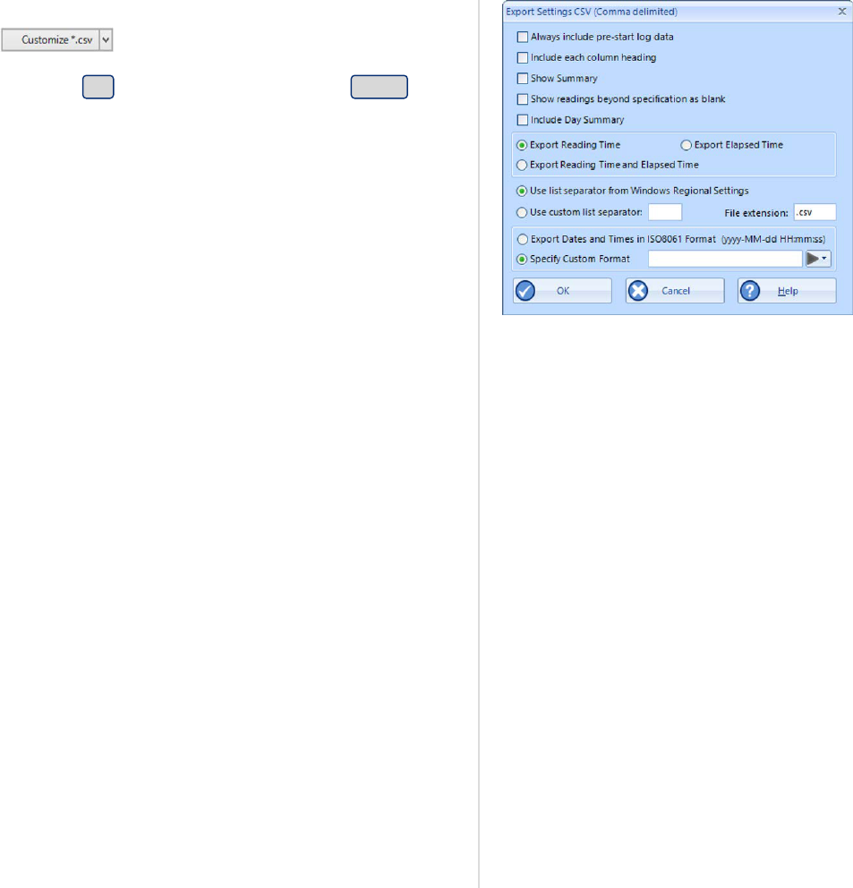
Figure 145: Customizing Export Options
You can select which extra information will be included separately for each of the different
export formats. Click the down arrow in and select the export format you wish to
adjust.
In this window adjust the options to suit and click OK to save your selection. Click Cancel if
you wish to discard any changes you have made.
You can include or exclude:
l
pre-start logged data;
l
column headings;
l
the trip summary;
l
readings beyond specifications;
l
the day summary for loggers that store this type of data; and
l
reading time, elapsed time, or both.
The options for the PDF files are more extensive than for other files, please see PDF files on
page141
For CSV files you can select several additional options:
l
a custom list separator
CSV files normally use a comma as a separator between individual values of a row. LogTag
Analyzer allows you to define which character is used. The default setting for this option is
Use list separator from the Regional Settings, which uses the character defined in the
"Regional and Language Options" in the Windows Operating System. For some regions the
resulting file is strictly speaking no longer a CSV file, however it maintains compatibility
with the import of CSV files into MS Excel.
Select Use custom list separator and enter your chosen character to use this instead of the
default character.
l
A custom date and time format
You can select Export Dates and Times in ISO8061 format (this is the default setting for a
new installation). For each recorded reading two fields are generated: a date field in the
format YYYY-MM-DD and a time field in the format HH:mm:ss (24 hour clock). Other dates
and times in the header of the CSV file also use this format.
Alternatively, you can select Specify Custom Format and use your own date/time format.
Selecting the elements of the date and time format works the same as in Date and Time
Format on page182, so is not further explained here. If you choose not to specify a time
format, 24 hour format will be provided. If you mix date and time fields (for example
HH:mm YYYY ss) the string will appear in the date field, and the time field will be empty.
Customising the software
LogTag
®
Analyzer User Guide
page 180

When you open a CSV file with Microsoft Excel you may not see these date and time
formats as entered. Excel formats any strings resembling date and time using its
own date/time format, which is typically based on the regional settings of your
operating system.
l
a file extension
CSV is the standard extension, but you can choose your own extension here.
Attaching files to emails
Figure 146: List of file formats for attaching via Sendmail.
Here you select the file formats for the email attachment created through the Send Mail
command when Sending a file by email direct from Analyzer.
Note: If you select an item in the list of Send Mail file formats, the format is
not
automatically selected for export. If you wish to automatically upload files to an FTP
site or email them using the automatic emailing function you need to select them in
this section for automatic export, and also enable them in the FTP settings as
described on page166 and the SMTP and email settings as described on page163.
Copying Charts
You can copy the contents of a chart to the Windows clipboard by pressing CTRL-C while the
chart tab is active.
Here you can select which format the data should have, and which resolution.
Report appearance
The remaining fields on this page influence the appearance of the report tab. You can decide
the default zoom level (Full page, Page Width and Custom), as well as a custom percentage. You
can also define the alternating row color.
Customising the software
LogTag
®
Analyzer User Guide
page 181

Date and Time Format
Figure 147: Date and time options
Here you can set how dates and times are displayed in all tabs, reports and exports.
Short Date, Long Date and Default time use the settings from the Regional and Language
settings of the Windows operating system, accessible through the Windows Control Panel.
You can customize how the date or time information is displayed by selecting Custom Date or
Custom Time and combining the elements as listed in the tables Mean Kinetic Temperature on
page136. The letters must be in the correct case (for example, "MM" in the date string, not
"mm" as you would use for time value). You can use the characters '.', '/', ',' or '-' to separate
elements, but you cannot add text.
Element Meaning
d Day of month as digits with no leading zero for single-digit days.
dd Day of month as digits with leading zero for single-digit days.
ddd Day of week as a three-letter abbreviation.
dddd Day of week as its full name.
M Month as digits with no leading zero for single-digit months.
MM Month as digits with leading zero for single-digit months.
MMM Month as a three-letter abbreviation.
MMMM Month as its full name.
y Year as last two digits, but with no leading zero for years less than 10.
yy Year as last two digits, but with leading zero for years less than 10.
yyyy Year represented by full four digits.
Table 29: Date options
Customising the software
LogTag
®
Analyzer User Guide
page 182
Element Meaning
h Hours with no leading zero for single-digit hours; 12-hour clock.
hh Hours with leading zero for single-digit hours; 12-hour clock.
H Hours with no leading zero for single-digit hours; 24-hour clock.
HH Hours with leading zero for single-digit hours; 24-hour clock.
m Minutes with no leading zero for single-digit minutes.
mm Minutes with leading zero for single-digit minutes.
s Seconds with no leading zero for single-digit seconds.
ss Seconds with leading zero for single-digit seconds.
t One character time-marker string, such as A or P.
tt Multi character time-marker string, such as AM or PM.
Table 30: Time options
For example, if the date was 2 January 2012 and the date format was defined as yy-M, dd the
date would be displayed as 12-1, 02.
A sample of the chosen date and time format is displayed in the sample box.
Please note that due to some regional limitations of the Windows OS, not every region supports
each of the settings above.
This setting does not affect how the date and time information is stored in a *.ltdx
file, only how the information is shown.
Time zones
Each LogTag
®
stores a time zone along with the real time. This allows recipients to view data
from a logger in their own local time, even if it originated from a different time zone. Most
loggers store the time zone of the computer used for configuration, but for some the time zone
can be specifically defined during configuration, for example in USB PDF loggers, where it is
often desirable to set the time zone of the recipient.
The Display Time Zone field allows you to select which time zone LogTag Analyzer will use. It
can be accessed by clicking Options from the Edit menu and selecting the Date and Time tab.
Customising the software
LogTag
®
Analyzer User Guide
page 183
Time zone What is displayed
Local PC Time
Zone
All times are displayed in the time zone of the computer used for viewing the data.
This is the most commonly used option, as it displays the dates and times on screen
in your local time zone.
Note, that this is not the same as the download time zone, if you
were sent a file from a logger downloaded in a different time
zone.
Download Time
Zone
All reading times are displayed relative in the time zone of the computer
used for downloading the data.
Configuration
Time Zone
All reading times are displayed in the time zone of the computer used for
configuring the LogTag
®
.
You would use this option if you wanted to view the data in the same way
the sender of the logger would see it.
UTC/GMT Time
Zone
All times are displayed in Universal Time Coordinates, or Greenwich Mean
Time representation.
This is the best option when comparing different loggers from different
senders in different time zones.
Use logger
display clock
when available
If selected, all times are displayed relative to the clock that is showing on
the display of the logger, if it is equipped with a display that has a clock.
You would typically select this option, if you want the logger's display
clock to show the same time values as the Report generated by LogTag
Analyzer.
Use PDF time
zone for USB
loggers
If selected, reading times are displayed in the time zone set in the USB
PDF logger.
Regardless of the option you select, the recorded data inside the LogTag
®
are not affected.
Customising the software
LogTag
®
Analyzer User Guide
page 184

Communication Ports
Figure 148: All COM ports disabled, USB enabled
LogTag Analyzer supports communication with multiple ports simultaneously, so it is possible
to connect and use more than one interface cradle at the same time. Each time you use LogTag
Analyzer to configure, download or hibernate a logger it needs to check each enabled port to
see if an interface with a logger is attached to that port. In this dialogue you can define, which
communication ports should be checked for connected interface cradles. The more ports you
leave enabled, the longer it will take LogTag Analyzer to establish which ports have interfaces
connected, and which don't.
You should therefore only enable ports you plan on connecting an interface to. Ports not used
for communication with LogTag
®
products should be excluded, which speeds up
communication.
When you first install LogTag Analyzer, all COM ports are disabled by default, as the most
common method of communicating is via USB interfaces.
This is especially useful if you have Bluetooth devices connected to your computer, which
generate a large number of virtual COM ports. It can take LogTag Analyzer a long time during
download or configuration to detect if these virtual ports have an interface connected, so
disabling the ports significantly improves communication time. Any new COM port established
after you disable all serial ports will also be automatically disabled.
If you wish to use an RS232 serial interface, you can clear the check box Disable all serial ports.
Customising the software
LogTag
®
Analyzer User Guide
page 185

User Server
Figure 149: Running LogTag Analyzer as administrator
To enter or change these settings LogTag Analyzer must be started with local
administrator privileges. Close LogTag Analyzer, right click its shortcut and click Run
as administrator. Make the changes after you have provided Administrator credentials,
then close LogTag Analyzer and start as usual. You cannot connect to User Server while
logged into LogTag
®
Online.
The User Server options define if and how LogTag Analyzer should connect to the LogTag
®
User
Server software. If you do not have LogTag
®
User Server software installed on your computer or
network, you will not need to changes these settings. Connection to the LogTag
®
User Server
software is typically only used in multi-user environments or if your organization requires
compliance with the US FDA 21 CFR Part 11 regulations for use of digital signatures that are
controlled by a central administrator.
The settings required in these fields will be provided by your network administrator. You will
also need to select I agree to be able to store these settings. Once a valid connection to the
LogTag
®
User Server software has been established, you will be required to provide a valid user
name and password (How users log on on page199) to continue using LogTag Analyzer.
Caution: If the LogTag
®
User Server software runs on a different computer, you need to
be connected to that computer via a LAN or WAN to use LogTag Analyzer software or
make any changes to these settings. You will not be able to use LogTag Analyzer if you
cannot establish a connection to the User Server software.
Customising the software
LogTag
®
Analyzer User Guide
page 186

Figure 150: User Server options
For more information please refer to the Digital Signatures Suite web page, which can be
accessed via the LogTag
®
website.
Customising the software
LogTag
®
Analyzer User Guide
page 187
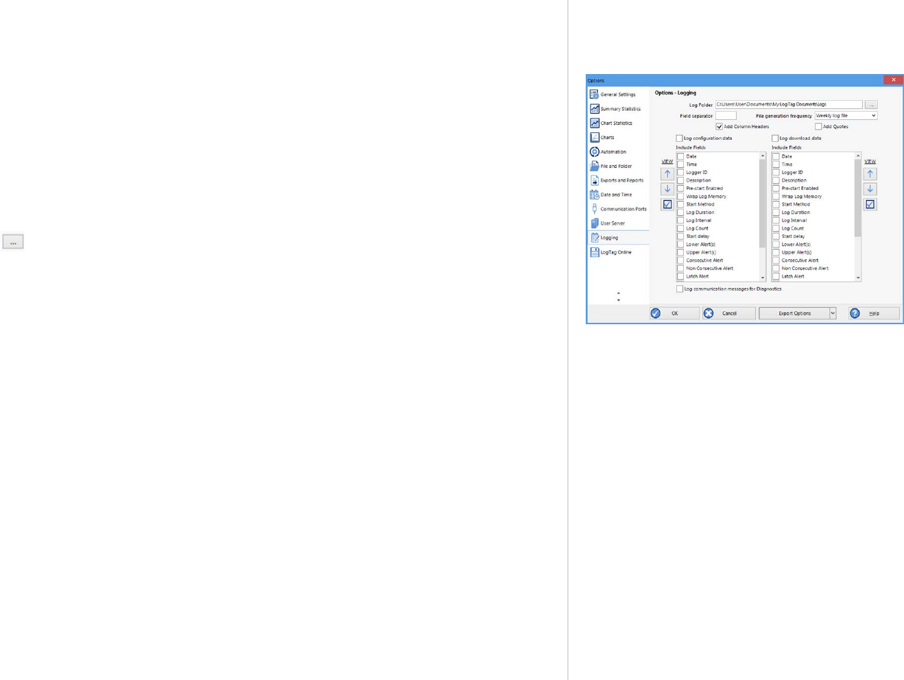
Activity Logs
Figure 151: Configuration logging options
It can sometimes be useful to keep a record of the configuration and download logs of a
LogTag
®
logger. LogTag Analyzer can store a number of different logs in text files. Settings for
what is stored and where are made in the Logging window.
When the Log configuration data option is ticked, the selected parameters are written into a
text file, which is named "Analyzer_config_log_YYYY_TTT.txt". When the Log download data
option is ticked, a second file is generated, named "Analyzer_download_log_YYYY_TTT.txt"
YYYY is the current year, and TTT is a string, the composition of which is dependent on the
frequency of the log generated. You can opt to generate a new file every day, every week or
every month. We recommend to choose this depending on the frequency and quantity of
loggers configured and downloaded, the default is every week.
Clicking will allow you to select a Log folder of your choice where the log files will be
stored. This folder is also used for the FTP and SMTP logs. For each logger configured or
downloaded a new line is started in the corresponding text file; individual entries in each line
are separated by the character specified in the Field separator text field, and you can choose to
also enclose each value in quotation marks by selecting Add Quotes.
Customising the software
LogTag
®
Analyzer User Guide
page 188

Figure 152: Parameters
available for Configuration
logging
Figure 153: Parameters
available for Download
logging
You can view the files by either browsing to the log folder and opening the file with a text
viewer, or you can click VIEW and open the log for viewing in LogTag Analyzer's internal
browser.
Different parameters are available for configuration and download logging.
You can change the order of the entries in each line by highlighting the entry and clicking
or . Clicking the check box enables all parameters to be included in the log file.
For diagnostics purposes you can select LogCommunication Messages. This generates an
encrypted log file which you can send to LogTag North America Inc for analysis. The feature
will be disabled when you next re-start LogTag Analyzer.
Customising the software
LogTag
®
Analyzer User Guide
page 189
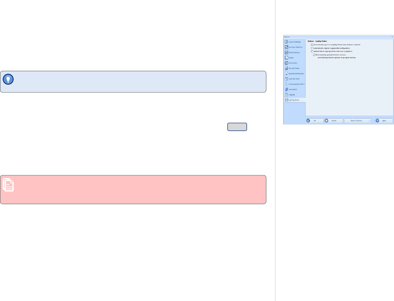
LogTag
®
Online
Figure 154: LogTag Online Option Settings
Here, you can control some aspects of the LogTag® Online connection.
Automatically sign in to LogTag
®
Online when Analyzer is started
This setting allows you to use your previously entered credentials to automatically sign into
LogTag
®
Online when you start LogTag Analyzer the next time.
If you are a member of multiple teams you will be signed into the team that was active
when you last closed LogTag Analyzer.
Automatically register loggers LogTag
®
after successful configuration
If this setting is enabled, each logger you configure will be automatically registered to the
LogTag
®
Online account you are currently signed in with. If no user is signed in during
configuration, you will be prompted to complete the sign-in process. If you press Cancel in this
sign-in window, the logger will still be configured. Registration of the logger then depends on
whether you store and resume pending uploads below or not.
Upload files to LogTag LogTag
®
when user is signed in
Enable this to automatically upload a copy of every file generated when downloading a logger.
Uploading files to LogTag
®
Online can only be done automatically when a file is
generated. You will not be able to upload files already stored locally, i.e. when re-
downloading a stopped logger for which a file already exists.
Store pending uploads between sessions, automatically resume uploads on
program start up.
Enable this to resume any uploads that were interrupted, or to start uploading when you next
sign in. This includes both downloaded files and logger registrations.
Customising the software
LogTag
®
Analyzer User Guide
page 190

Importing and Exporting Option
Settings
LogTag Analyzer's option settings can be exported and then imported into other installations
of LogTag Analyzer. This is useful if you want to distribute settings to multiple users on the
same computer or copy settings from one computer to another. You can also use this if you are
upgrading your computer, and want to transfer the settings to the new computer.
You can access these functions from the Edit - Options dialogue.
Customising the software
LogTag
®
Analyzer User Guide
page 191

Exporting the Options Settings
Figure 155: Selecting the options settings to be exported
With LogTag Analyzer open, select Edit - Options and click on Export Options. If the button
displays Import Options, click the down arrow, then click Export Options.
A window will open, where you can select the option settings that will be exported.
Select all applicable check boxes, or choose Select All to export all settings. Only settings with
the check box enabled will be exported.
You need to enable at least on option, or you will receive an error.
Click OK and in the file explorer window that opens browse to a directory and enter the file
name of the export file. The *.asxml file extension will be added automatically.
Figure 156: Selecting the export file name and location
Once you click Save, the export file will be written to the folder specified, and you will receive
a confirmation message of the successful export.
Figure 157: Successfully exported settings file
Customising the software
LogTag
®
Analyzer User Guide
page 192
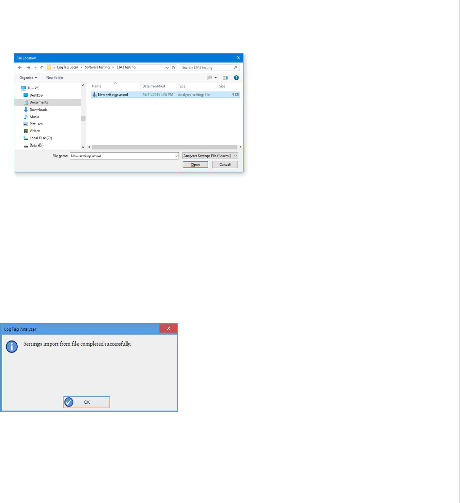
Importing the Option Settings
You can use one of the following methods to import option settings into LogTag Analyzer.
l
With LogTag Analyzer open, select Edit - Import Options.
Figure 158: Import options dialogue
Browse to a previously stored *.asxml file and click on Open.
l
Double click on a *.asxml file in Windows Explorer, on the Desktop or in an email
attachment.
l
Drag and drop a *.asxml file onto the LogTag Analyzer icon on the desktop.
l
Open the file via the File - Open dialogue in LogTag Analyzer.
Only settings present in the *.asxml file will be imported. If a setting already exists in LogTag
Analyzer, and a different setting is imported, the new setting from the imported file will
overwrite the existing setting.
Once the import is complete, you will see this dialogue.
Figure 159: Import successful
If there are any problems with the import file, for example a file format incompatibility, an
error message will be displayed showing the import failed.
Customising the software
LogTag
®
Analyzer User Guide
page 193

You cannot import a settings file generated with LogTag Analyzer version 2. You will receive
the following error message:
Customising the software
LogTag
®
Analyzer User Guide
page 194

Chapter 5
Appendix
Code Pages 196
Connecting to LogTag® User Server 199
Connecting to Gmail 202
Office365 email support 205
Getting more help 206

Figure 160: ASCII Table of printable characters
A computer determines which character to display based on a table of
values, which is specific to a written language. This table is often
referred to as the code page.
A small number of characters are independent of a computer's input
language. These are '1-9', 'a-z', 'A-Z' and some special characters, for
example punctuation and brackets. These are listed in the ASCII table
as shown.
An additional 128 characters are available, which are specific to each
code page. The following examples show the differences between the
available characters for the Latin and Thai code pages.
Figure 161: Code page 847, Thai languageFigure 162: Code page 1252, Western languages
Appendix
LogTag
®
Analyzer User Guide
page 196
Code Pages

Figure 163: Accessing charmap.exe on Windows 10
In LogTag Analyzer password and user ID fields are text entry fields.
The code page is used to determine the characters LogTag Analyzer
displays on screen and stores inside a logger. Which code page is
selected depends on which input language you have selected for your
computer. When the LogTag
®
is downloaded in a different country,
the user ID is displayed with the characters from the code page who's
reference is stored in the logger. This is possible because all Windows
code pages get installed as part of the operating system, although only
one is used at a time to display characters.
Passwords are always displayed with the asterisk character, but you
will need to type them into a confirmation dialogue (especially if the
password on download feature is enabled). You can use the Windows
character map to enter characters that are not available in your
language. To access the Windows character map, enter charmap.exe in
the "Search" or "Run" box of the Start menu, depending on your
operating system, and press Enter.
Some code pages make more than these extra 128 characters available,
but this requires more storage in the logger's memory, which reduces
the number of characters available for password and user ID. These
languages are Chinese (Traditional), Chinese (Simplified), Korean and
Japanese. For every character not in the ASCII character table on the
previous page the number of characters that can be stored is reduced
by one. This means a password can be as short as 3 characters, and a
description as short as 19 characters (or 18 characters for a TRID30 or
TRED30).
Appendix
LogTag
®
Analyzer User Guide
page 197

These samples shows the extended character overview and a character
subset.
Figure 164: Code page 932, Japanese language, subset 91
Figure 165: Code page 932, Japanese language
You can find more information about the history and technical
background of code pages via a number of online references.
Note: Although you can use the Windows character map to
confirm a password on download, you cannot enter characters
as a new password or description that are not available in
your chosen input language with this method. If you want to
use different characters you must switch the input language
of your computer. Please refer to the instructions relating to
your specific operating system how to do this.
Appendix
LogTag
®
Analyzer User Guide
page 198

Connecting to LogTag
®
User Server
To use Digital Signatures, LogTag Analyzer must be connected to the LogTag
®
User Server
software. When connected, all users are required to log on to LogTag Analyzer before they can
use the software. To find out how to connect LogTag Analyzer software to the LogTag
®
User
Server software please see User Server on page186
How users log on
Figure 166: Logon request when connected to User Server
Figure 167: Unable to log on to User Server software
If LogTag Analyzer is connected to the User Server, the logon screen as shown one on the right
is displayed when LogTag Analyzer is started. You can also click the Logon icon in the
toolbar or click Logon from the User Server menu. For users to successfully log on to the
software for the first time, they must enter the username and password assigned to them by
the User Server administrator.
Note: To maintain compliance with the FDA CFR 21 Part 11 guidelines, you cannot
connect to LogTag
®
Online while being connected to User Server and vice versa. These
options are mutually exclusive.
The password can be changed after the user has logged on (See How users change their
password on page201). You cannot change the Username.
Usernames are typically not case sensitive, however passwords are, which means that "Bob
Smith" is the same username as "BOB SMITH" and "bob smith", however, entering a password
of "bob" rather than "Bob", for example, is considered to be different.
Once logged on, you will be able to use all functions to which the User Server administrator has
given you access.
If your logon failed, you will see the Logon Failed message.
Every log on attempt, whether successful or not, will be recorded automatically in the audit
logs. As a security measure, the network administrator may configure LogTag
®
User Server so
that a user account becomes blocked after a certain number of consecutive failed log on
attempts. Please contact your network administrator if you have problems with the log-on
process.
Appendix
LogTag
®
Analyzer User Guide
page 199

To log off, click the Logoff icon on the toolbar , or click Logoff from the User Server
menu. When you exit LogTag Analyzer you will automatically be logged off.
Appendix
LogTag
®
Analyzer User Guide
page 200

How users change their password
Figure 168: Changing a User Server password
The User Server administrator may permit you to change your logon password. To do so click
Change Password from the User Server menu. You will need to supply your current logon
password, then enter the new password and a confirmation.
The User Server administrator may enforce certain password rules. For example, they may
require a minimum number of characters (digits, letters or symbols) or a minimum number of
digits to be included in the password, or both. Please contact your User Server administrator if
you have problems with the password change process.
Passwords should be chosen so they are difficult for someone else to guess. Following are a few
points to remember when changing a password:
1. Do not use something that is personal to the user. Birth dates, license plate numbers,
names of family members, types of vehicles owned, favorite foods and address of
residence are all examples of passwords that should NOT be used.
2. Do not write your password down.
3. Change your password on a regular basis.
If users forget their password, the User Server administrator will be able to change it. However,
administrators will not be able to see and therefore inform users what their current password
is.
Appendix
LogTag
®
Analyzer User Guide
page 201
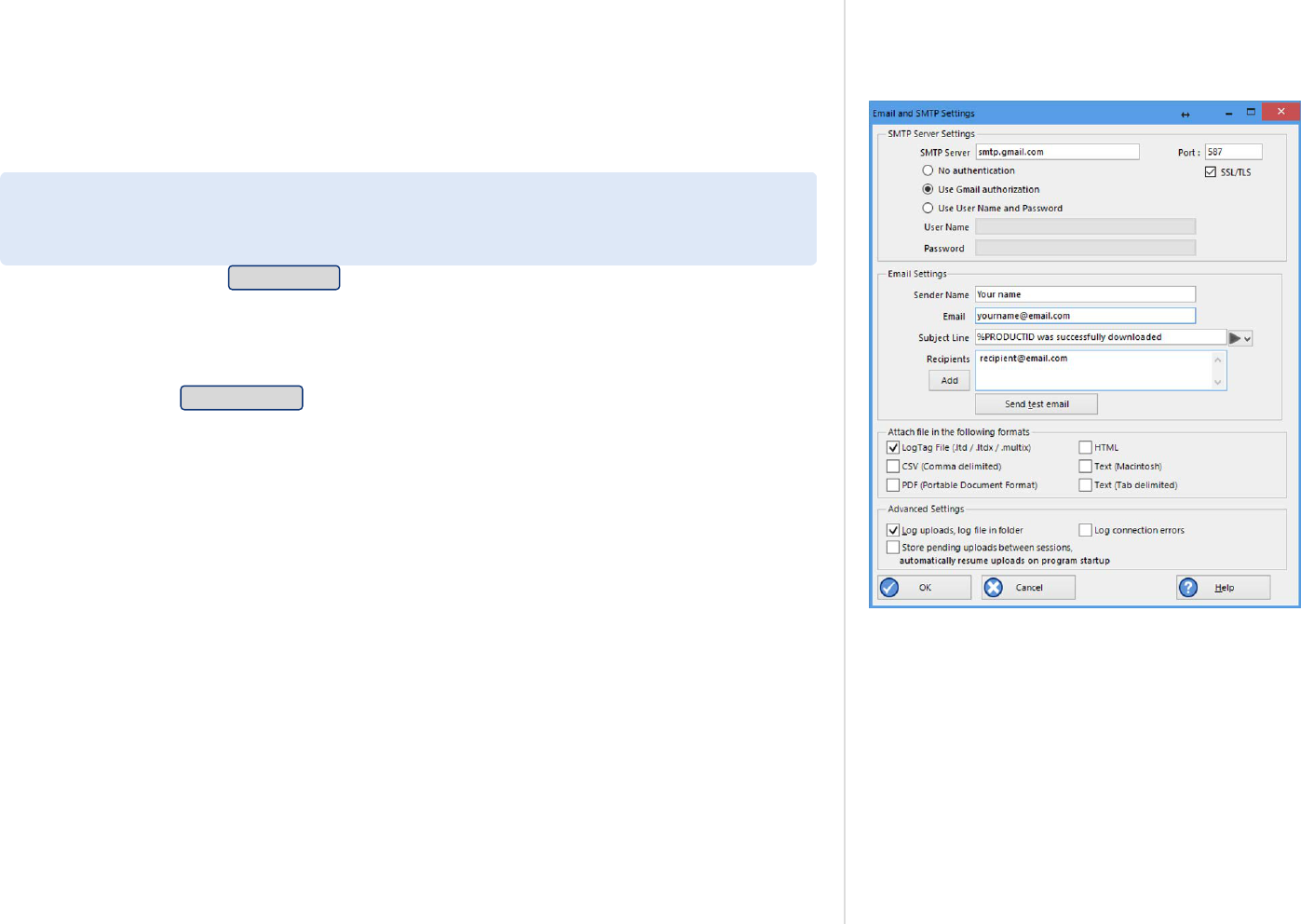
Connecting to Gmail
Figure 169: Gmail settings selected
LogTag Analyzer has the ability to connect to Gmail's SMTP server using your Gmail account.
Analyzer now supports the OAuth2 authorization method, which makes it more secure to
connect but requires a few simple steps extra when you initially set up automated email
sending.
If you already connect to Gmail with an earlier version of Analyzer you will have enabled the
option Allow less secure apps in your Google account settings. You can continue sending
emails this way without changing any of the settings in Analyzer, however, we strongly
recommend to use the more secure OAuth2 authorization method, as described below.
To use this method, select Email settings from the Automation tab in Options. You will see the
Email and SMTP settings dialogue. Click Use Gmail authorization - the SMTP Server, Port and
SSL/TLS fields will now be set up automatically.
Do not enter anything else in the SMTP Server Settings section of the dialogue. Complete the
remaining entries in the Email Settings, Attach file... and Advanced Settings sections.
Once complete, click Send test email. Have your Gmail logon and password details ready.
Appendix
LogTag
®
Analyzer User Guide
page 202

Figure 170: Enter your Gmail account details
Your default browser will now open. You will be asked to select which Gmail account you wish
to connect to. Enter the details of your Gmail account address.
Figure 171: Confirming the account password
Click Next and enter the account password.
Appendix
LogTag
®
Analyzer User Guide
page 203

Figure 172: Giving LogTag Analyzer permission to send
email on your behalf
Figure 173: Success message
Click Next and confirm that you agree to giving LogTag Analyzer permission to send email from
your Gmail account.
Click Allow and your browser will show a message that it has successfully communicated with
LogTag Analyzer and set up the appropriate permissions.
You can now close the browser window.
Figure 174: Successfully connected to the Gmail SMTP server
Figure 175: Time-out from SMTP server
At the same time LogTag Analyzer will inform you that the connection to the Gmail SMTP
server was successful.
When you now use the automated email function, the Gmail email will appear as the sender.
For security reasons this process needs to be completed within one minute. If you exceed the
allowed time LogTag Analyzer will display a time-out message.
Unless you have other applications that need to connect to your Google account, you
can now switch the setting Allow less secure apps to Off. You can check which other
applications access your Google account in the section Apps with access to your
account in the account settings.
Appendix
LogTag
®
Analyzer User Guide
page 204

Office365 email support
LogTag Analyzer can now connect to Office365's SMTP server using your Office365 account.
To use this method, select Email settings in Edit - Options - Automation.
Complete SMTP Server, Port and SSL/TLS fields as follows:
Server Name: smtp.office365.com
Port Number: 587
Encryption Method: Enable SSL/TLS
Click Use User Name and Password and type your Office365 account email into the User Name
field and your Office365 account password into the Password field.
Figure 176: Settings for Outlook 365
If you use two factor authentication for your Microsoft account you will need to perform extra
steps, or sending emails will fail:
1. You will need to generate an app password that specifically allows connection to
applications that are unable to accept two factor authentication passwords.
This is done on the Security basics page for your Microsoft account, in the More security
options section. Create a new app password (or use the existing one). Please refer to the
Microsoft documentation on this subject if you need further assistance generating this
password.
2. Once generated, enter this password in the Password field.
You can now complete the remaining entries in this window, then test the SMTP settings by
clicking Send Test Email.
Appendix
LogTag
®
Analyzer User Guide
page 205

Getting more help
Figure 177: Requesting Help via the Help Menu
If you run into a problem with your logger, you can click Request
help... from the Help Menu to contact the support team at LogTag
North America Inc. When you select this command, LogTag Analyzer
will collect information from your system, that assists in diagnosing
issues.
LogTag Analyzer generates some or all of the following files:
l
diagnostics.txt.gz
This file includes information about your operating system version,
installed languages, temporary folders, LogTag Analyzer version
numbers and other system related information in a compressed
format
l
UserProfile.profile.gz
This file contains the settings for LogTag Analyzer in a compressed
format and can help identify issues with path names and sharing
settings
l
AnalyzerErrorLog.dat
This file contains LogTag Analyzer's error log
l
XXDownloadFilenameXX.ltm
LogTag Analyzer generates a special download file for any USB
logger and any logger in an interface attached to the PC. These file
(s) will have a *.ltm file extension (Logger Total Memory), which
can only be viewed with special diagnostic software by LogTag
North America Inc, but not with LogTag Analyzer software
While the software is collecting this information, a message is
displayed. It is important you do not remove any loggers during this
process.
Appendix
LogTag
®
Analyzer User Guide
page 206

Figure 178: Diagnostics email message
LogTag Analyzer will then open a message window, allowing you to
enter of your details.
Field What to enter
From Your email address, so we can contact you about
the problem
cc Email addresses of anyone you wish to share this
information with.
Message body Include as much detailed information in your
email as possible about the problem, such as what
you were doing at the time, or what application
the LogTag
®
product is used in.
Add file You can add files that help to describe your problem,
such as a screenshot or a specific LogTag
®
file that
causes the issue. You can easily generate a screen shot
with Windows' own snipping tool and save it to a file
before attaching it.
Once you have entered all details, click Send to submit the message to
LogTag North America Inc.
Note: When you click Request help... from the Help Menu
again, any existing files in the Diagnostics folder will
automatically be deleted. If you wish to keep a copy of the
files and the report LogTag
®
we suggest you put your own
email address into the cc field of the message.
Appendix
LogTag
®
Analyzer User Guide
page 207

Unsupported Loggers
Figure 179: Software update is available for an unrecognized file or logger.
Figure 180: Latest software is already installed - a diagnostics email is required
Occasionally, you may come across a logger that the software doesn't
support.
In most cases, such a logger simply is newer than the software
understands. In this case, you will be notified that a software update is
available. You should update the software to the latest version, which
in most cases will resolve the issue. Click Download to start the
process and follow the on-screen instructions. A detailed description
of the update process can be found in Upgrading LogTag Analyzer on
page24.
In rare circumstances the logger or file contains information that
cannot be decoded, even with the latest software. This can happen if a
logger was operated beyond its safe battery life, and some of its
memory contents are no longer correct. For such a logger you can send
a diagnostics email to LogTag North America Inc with the memory
contents of the logger attached. This process is described in detail in
Getting more help on page206.
Appendix
LogTag
®
Analyzer User Guide
page 208

Damaged Calibration
Figure 181: Logger containing invalid calibration details
If you see this error message the logger has suffered a problem with
its calibration data.
If the problem only affects the calibration area of the memory there is
a good chance your logger (and possibly the logged data) can be
recovered using the LogTag
®
Calibration Restore tool.
Click Yes to collect diagnostics information specific to this problem.
Once you have sent the diagnostics email you will receive further
instructions from LogTag North America Inc about how to proceed.
Appendix
LogTag
®
Analyzer User Guide
page 209

Recovering from a failed firmware update
On the rare occasion that a USB logger firmware update fails, you will
not be able to configure or download the logger until it is recovered.
You can recognize a failed firmware upgrade from a permanently lit red
LED, or the word boot if the logger has a display.
When you try to configure such a logger, the progress pane shows the
following:
An extra button Recover logger is available below the Rescan button:
Click the button, and the recovery window is displayed on screen.
Figure 182: Discovering loggers requiring a recovery process
To be able to successfully recover a logger with a partial firmware
upgrade applied, you must have firmware for this model stored locally
on the PC. Typically, this is not an issue of you want to recover from a
failed upgrade on the same PC, however, if you are trying to recover a
unit that was upgraded on a different PC you will need to make sure
you check the internet for a software update, and if one is available,
install it (this will also install any available firmware updates).
Figure 183: Recovery on progress
Only one logger can be recovered at any one time. The
software will select and repair the first logger that is reported
by its discovery process. If you need to repair multiple loggers,
please recover them one by one.
The recovery process will proceed automatically once a logger is
discovered. It will take up to two minutes until you see the following
success message:
Appendix
LogTag
®
Analyzer User Guide
page 210

Figure 184: Logger recovery successful
Click Close to complete the process, or add another logger for recovery
and click Again.
The logger will be hibernated after the process is complete; you
will need to configure and start the logger if you want to use it
for recording data.
If the process fails, you will see an error such as this:
Figure 185: Logger recovery failed
Try the recovery process once more by clicking Again. If the process
fails again, please contact support for assistance.
Appendix
LogTag
®
Analyzer User Guide
page 211

A
Activity Logs
188
Advanced Alert Settings
59
Alert Processing
57
Alerts
54, 57, 59, 70, 73, 80, 82, 107
Aligning Charts
114, 116
Analysing the results
101
Appendix
195
Automatic e-mailing and uploading to FTP
sites
139, 162
Automatic Re-Configuration after Download
79
Automatically calculated statistics
134
Automatically save data files to default folder if
source is read only
161
Automation
79, 139, 146, 160, 162, 166, 168, 176,
202, 205
Average Reading
134, 137
B
Basic FTP settings
166
C
Calling up previous results
100
Chart annotations
104, 120, 126
Chart Display
103, 114
Chart Legend
111
Chart Statistics
113, 122, 130, 152, 154
Charts
41, 57, 59, 104-106, 111, 114-116, 136, 155,
181
Code Pages
196
Combining charts onto a single chart
99, 111
Communication
Interface
10, 14-15, 22, 28, 36, 47-48, 50, 52, 77-
79, 83, 85, 93, 96, 140, 145, 160, 185, 206
Ports
46
Communication Ports
185
Configuration
Profile
35, 50, 63, 85-86
Recorders
32, 44, 46, 49-50, 53-54, 57, 60, 63, 66,
69, 73-74, 78-80, 82-87, 89, 91, 99, 135,
149, 153, 160-161, 163, 166, 184-185, 188,
190
Configuration Profiles
84
Configuring LogTag®(s) for use
53
Connecting the Interface
47
Continuous operation
79
Copyright
2
D
Data Display
127
Dates and Times
44, 180, 182
Day Summary Display
131
Default display time interval
149
Degree Minutes
135, 152
Digital signatures
95
Display
39, 44, 60, 67, 103, 114, 124, 127, 130-
131, 154, 158, 161, 176, 183
Display Logger
60
Display readings after successful download
161
Display X items in my most recently used
list
176
Displaying statistics
130
E
Edit Menu
34
Enable automatic download of readings from
LogTag®s
160
Exports and Reports
138, 142, 165, 167, 179
F
FDA
96, 143, 186, 199
File and Folder Settings
32, 140, 171
File Menu
32
File Name
86, 172
File type
*.asxml
192-193
*.ltd
32, 95, 113, 120, 138, 141-142, 161, 176, 179,
183
Index

*.multi
32, 41, 89, 99-101, 106, 109, 111, 114, 119-
120, 126, 129, 139, 156, 186
*.pdf
39, 53, 61, 66, 68, 70, 89, 95, 99, 138, 141, 149,
179, 183
*.sltd
32, 99
Finding your software version
23
Folder Name
174
FTP
26, 32, 40, 95, 100, 138-139, 162, 166, 181,
188
FTP settings
166, 168
G
General Settings
149
Getting a copy of the software
17
Getting more help
206
Getting results from LogTag®s
92
H
Help Menu
23, 39, 206
Hibernation - Prolonging battery life
82
Hiding Readings
112
How secure is my data
96
How users change their password
201
How users log on
199
I
Indicator
57, 59
Indicators
14, 51, 57, 63, 73, 76, 89
Inspection and download mark zoom
109
Installing the software
15
Introduction
10
L
Language
67, 148-149, 180, 182
Logging related Configuration Parameters
54, 57
LogTag® Data files
95
LogTag® Data files (*.ltd)
142
LogTag® Menu
35-36
M
Manual Scaling
107
Mean Kinetic Temperature
66, 134, 136, 152
Menu commands
31
Menus and Toolbars
31
Minimum, Maximum and Average Charts
41
O
Only show the latest set of readings after
download
161
P
Page Setup
33, 132
Password
36, 38, 48, 52, 75, 78-80, 82, 88, 96,
144, 164, 166, 168, 186, 199, 201-202, 205
Rules
81
PDF files
39, 95, 138, 141, 180
Pre-start data collection
80
Print preview toolbar
42
Printing the results
132
Profile Control Buttons
85
Profile File Controls
86
Profile Storage File Name and Path
86
Profile Window Controls
87
Profiles Grid
85
Protecting Recorded Data
81
Q
Quickly re-configuring LogTag®s
78
R
Reconfigure with same settings after automatic
download
160
Registry
167
Report Display
124
Restricting Access
80
Results from LogTag®
92
S
Saving a file for use in spreadsheets
140-141
Saving a Multi Chart file
99
Selected LogTag® Data files (*.sltd)
99
Sending a file by e-mail direct from
Analyzer
138
Show temperatures in
149
SMTP
26, 139, 162-163, 188, 202, 205
Gmail
163, 202
SSL
163, 166, 202, 205
SMTP and e-mail settings
163
Software Updates
150
Special Chart Tabs
114
Standard Deviation
134, 137
Starting and using the LogTag®
83
Summary Display
130-131
Summary Statistics
152
System requirements
15
T
The installation process
19
Toolbar commands
40
U
Uniqueness
177
Upgrading LogTag Analyzer
24, 150
User Server
26, 33, 38, 41, 96, 143, 186, 199, 201
User Server Menu
38
V
Verify Access Password
82
Viewing file properties
98
W
Welcome
20
G - W
LogTag
®
AnalyzerUser Guide
page 213

Window Menu
37
Working with batches of LogTag®s
52
G - L
LogTag
®
AnalyzerUser Guide
page 214
