
MOBOTIX Camera Software Manual
© 2020, MOBOTIXAG

TOC
Frequently Asked Questions 26
Quick Links 26
Getting Started 29
Views of the MOBOTIX Camera 29
The Most Important Settings of the MOBOTIX Camera 32
Saving the Configuration 33
General Remarks on Storing Camera Settings 34
News in This Release 35
The System Platform MOBOTIX7 35
The New M73 With 3 Modules 35
Starting the MOBOTIX Camera 35
Activating the Boot Menu 35
Keys of the MOBOTIX Cameras 36
Recovery Operating System 37
Additional Information 37
Reference 38
Screens of the MOBOTIX Camera 38
The Live Screen of the MOBOTIX Camera 38
The Elements of the Live Screen 38
Elements of the Title Bar 38
Screens of the Camera 39
Image Control Elements 41
Other Elements 45
The Softbuttons 46
The Image Area 49
The Image Programs of the MOBOTIX Camera 53
Selectable Image Programs of the MOBOTIX Camera 53
The MxPEG ActiveX Plug-in for Internet Explorer 54
Prerequisites for Using the MxPEG ActiveX Plug-in 54
Installing and Running the MxPEG ActiveX Plug-in 55
2 / 557

Options of the MxPEG ActiveX Plug-in 55
The Best Frame Rate 57
Fast Images 57
High Resolution and Quality 57
The Focusing Aid of the Camera 57
Store Configuration 58
The Player of the MOBOTIX Camera 58
The Elements of the Player Screen 58
Elements of the Title Bar 59
Screens of the Camera 59
Elements of the Player Controls 61
The Event Story Buttons 64
The Softbuttons 65
The Image Area 68
Store Configuration 69
The MultiView Screen of the MOBOTIX Camera 69
The Elements of the MultiView Screen 69
Elements of the Title Bar 70
Screens of the Camera 71
Image Control Elements 72
The Softbuttons 73
The Image Area 77
Store Configuration 77
The Multiwatcher 77
Information on the Screen 78
The Live Image 78
The Last Stored Alarm Image 78
The Alarm List 78
Configuring Multiwatcher Screens 78
More Features 79
Setting the Screen as Start Page 79
Playing Sounds on Alarms 79
Stopping the Multiwatcher Screen 79
Storing the Configuration 79
Configuring the Multiwatcher 79
3 / 557

Changing the Configuration 79
Creating a New Screen 80
Deleting a Screen 80
Storing a Screen 80
The Guest Screen of the MOBOTIX Camera 80
The Elements of the Guest Screen 80
Elements of the Title Bar 81
Screens of the Camera 82
The Image Area 83
Image Control Elements 84
The Menu Link 84
Other Options 84
Register Other Cameras 85
Manually Entering Cameras 85
Automatically Searching Cameras 85
Deleting Entries 85
Manual Connection Test for All Cameras 85
Konfiguration sichern 86
The Admin Menu 86
Video Door Station 86
Bell Behavior and Video Mailbox 86
Konfiguration sichern 86
Managing MxBus Modules 87
MxBus Interface 87
Service Functions 87
Device 87
Notes on the Classic Mode 87
Assign Wires 90
Inputs 90
Outputs 90
Ringing 91
Negation 91
Output Defaults 91
Konfiguration sichern 91
Automatic Configuration 92
4 / 557

Description of Parameters 92
Konfiguration sichern 92
Entry Log 92
System Information 92
Information About This Camera 93
Temperature Table 93
Displayed Temperatures 93
Current Temperatures 93
Temperature History 93
Description of Parameters 93
Konfiguration sichern 93
System Messages 94
Structure of System Messages 94
Managing System Messages 96
DHCP Leases 96
List of DHCP Leases 96
Error Notification 97
Notification 97
Attaching Detailed Error Messages 98
Notification After Reboot 98
Konfiguration sichern 99
Security 99
Managing Users and Passwords 99
Creating New Users 100
Setting the Group 100
Deleting Users 100
Protecting a Camera From Public Access 101
Scheduled Access Control (Supervisor) 101
Super PIN 101
Konfiguration sichern 101
Locking out all Administrators by the "Owner" 101
Activating System Protection 102
Deactivating Scheduled Access Control 102
Managing User Groups and Access Rights 102
Creating New Groups 103
5 / 557

Deleting Groups 103
Setting the Access Rights 103
Screen 103
Function 105
Configuration 106
Minimum Access Rights 107
Setting Public Access 107
Protecting a Camera From Public Access 107
Scheduled Access Control (Supervisor) 107
Konfiguration sichern 108
Scheduled Access Control by Supervisor 108
Activating Scheduled Access Control 109
Deactivating Scheduled Access Control 109
Configuring Scheduled Access Control 109
Global Rule 109
Group Rules 110
Supervisor Status and Password 110
IP-Level Access Control 110
Allowing/Denying Access 110
Rules for Specifying Computers 111
Resolving IP Addresses and Domain Names 111
Order of Processing 111
Sample Configuration 111
Konfiguration sichern 112
Web Server Logfile 112
Table Description 113
Hardware Configuration 114
Manage Hardware Expansions 114
Connecting/Disconnecting Expansion Hardware 114
Diagnostics 115
Storing the Configuration 115
Saving and Restoring the Configuration of MxBus Modules 115
Saving the Configuration 115
Restoring the Configuration 115
Signal Out Profiles 116
6 / 557

Description of Parameters 116
Konfiguration sichern 116
Image Sensor Configuration 117
Store Configuration 117
Lens Configuration 118
Store Configuration 118
Page Administration 118
Language and Start Page 118
Start Page 118
Page Design 119
Page Options 119
Konfiguration sichern 121
Managing Softbutton Functions 121
Defining Softbuttons 121
Configuring a Softbutton 121
Editing Softbutton Functions 122
Konfiguration sichern 123
MultiView Screens 123
Screens 123
Cameras 123
Display Options 124
Actions 124
Actions Without Defined Cameras 124
Additional Actions With Defined Cameras 124
New Screen 125
Image Areas of a MultiView Screen 125
Configuring an Image Area 126
Selecting the Display Mode 127
Konfiguration sichern 128
Network Setup 129
Test Current Network Configuration 129
The Ethernet Interface 129
Quick Installation 129
The Ethernet Interface Dialog 130
General Interface Setup 130
7 / 557

IPv4 Ethernet Parameters 130
IPv6 Ethernet Parameters 131
Ethernet Hardware Options 132
Caution 132
Routing 132
Domain Name Service (DNS) 132
Zeroconf 133
IEEE 802.1X 133
IEEE 802.1Q 134
Konfiguration sichern 135
TCP Dump 135
General Options 135
Konfiguration sichern 136
Web Server 136
General Interface Setup 136
HTTPS Settings 137
MxWeb Settings 138
Replace the X.509 certificate and private key currently used by the camera 139
Replace the X.509 certificate and private key currently used by the camera 139
Generate self-signed X.509 certificate and X.509 certificate request 140
Procedures for Using and Creating X.509 Certificates 141
HTTPS with SSL/TLS is not Being Used 141
HTTPS with the Factory Default X.509 Certificate 142
HTTPS with an Individual, Self-Certified X.509 Certificate 142
HTTPS with an Individual, Externally Certified X.509 Certificate 142
Intrusion Detection Settings 143
Konfiguration sichern 145
SNMP Configuration 145
General SNMP Agent Configuration 145
SNMPv2c Configuration 146
SNMPv3 Configuration 146
Konfiguration sichern 147
Routing 147
Introduction 147
The Default Route 148
8 / 557

Network Routes 148
Using the Camera as a Router 148
Backup Internet Gateway 148
IP Forwarding 149
NAT for Outbound Traffic 149
NAT for Inbound Traffic 149
Additional Information 150
Konfiguration sichern 151
Dynamic DNS 151
Introduction 151
Configuring the DynDNS Client 152
Description of Parameters 152
Testing the Configuration 153
Ethernet Connection 153
Konfiguration sichern 153
General Settings of the Network Client 153
Description of Parameters 153
Konfiguration sichern 154
OpenVPN Configuration 154
Requirements 154
General OpenVPN Setup 154
Authentication 156
Logging Options 156
Manage VPN Certificates 157
FAQs and Error Messages 157
Frequently Asked Questions 157
Error Messages 158
Additional Information 159
Konfiguration sichern 159
MxMessageSystem 159
Network Distribution of Messages 159
General Interface Setup 159
Settings Depending on the Distributor Type 160
Konfiguration sichern 161
Message Configuration for MxBus Modules 161
9 / 557

Managing Messages 161
Configuring the MxMessageSystem of the Devices 162
Inputs 162
Outputs 163
RFID Modules 163
Audio feedback 163
Visual feedback 163
Keys 163
KeypadRFID 163
Sensors of the MX-GPS-Box 164
Sensors of the MxMultiSense 164
Radar Sensor of the MX-Proximity-Box 165
Storing the Configuration 165
Loading the Configuration 165
Generating a Default Configuration 165
Factory Defaults 165
Konfiguration sichern 166
Message Profiles for Action Groups 166
Konfiguration sichern 166
Storage 166
Storage on External File Server / Flash Device 166
An Overview of the Storage Methods 166
The Storage Methods in Detail – Configuring, Updating, Storage Structure, Maintenance, Best
Practices 170
RAM Storage With Ring Buffer 170
Storage in a Folder/File Structure on File Server 170
Description 170
Configuration 171
Storage on SMB/CIFS File Servers – Configuring the Camera 171
Storage on NFS File Servers – Configuring the Camera 173
Storage on Flash Device 174
Description 174
Configuration 175
Storage on Flash Device With Additional MxFFS Archiving on File Server/USB Device 175
Description 175
10 / 557

Configuration 176
Configuring the MxFFS Archive Options 177
Storage in MxFFS Archive With SD Card as a Fallback Buffer 178
Description 178
Configuration 178
Configuring the MxFFS Archive Options 179
Further Information Regarding Storage 180
Formatting Flash Devices for Storage Using MxFFS – Steps and Options 180
Formatting the Storage Target 181
Setting the Storage Limits 181
External Logging (File Server Storage Only) 183
Testing the Storage on the External File Server 183
Event Logging 184
Storage on SMB/CIFS File Servers – Configuring the Server 184
Storage on NFS File Servers – Configuring the Server 184
Updates, Maintenance and Best Practices Regarding MxFFS Archives 185
Exchanging Flash Devices With Activated MxFFS Archiving 185
Deactivate Recording and Synchronize MxFFS Archive 185
Formatting SD Card, Activating MxFFS Archiving and Recording 186
Measures to Take Upon a File Server Failure in Conjunction With MxFFS Archiving 186
Changing the Size of an MxFFS Archive 187
Konfiguration sichern 188
Archive Statistics 188
Displayed Charts 188
Storage Failure Detection 191
Configuring the Tests 191
Description of Parameters 191
Notification 192
Description of Parameters 193
Konfiguration sichern 194
Logos and Image Profiles 194
Managing Image Files 194
Upload Image File 194
View system images 195
Stored User Images 195
11 / 557

Displayed Information 196
Download Image Files 196
Images Loaded From URL 196
Konfiguration sichern 197
Logo Profiles 197
Logo Display 197
Profiles & Options 197
Adding a Profile 199
Deleting Profiles 199
Creating Frames 199
Konfiguration sichern 201
Image Profiles 201
Global Options 201
Profiles & Options 202
Adding a Profile 205
Deleting Profiles 205
Konfiguration sichern 205
Transfer Profiles 205
FTP Profiles 205
What is FTP? 205
Using the MOBOTIX Camera for FTP Transfers 205
Global Options and Profile Options 206
Streaming FTP 206
Profiles & Options 206
Testing Profiles 209
Adding a Profile 210
Deleting Profiles 210
Saving Created Profiles 210
Variables and Placeholders for Directory and File Names 210
Additional Possibilities for Creating Dynamic Directory and File Names 212
Konfiguration sichern 212
E-Mail Profiles 212
Using the MOBOTIX Camera for Sending Emails 212
Global Options and Profile Options 212
Profiles & Options 212
12 / 557

Testing Profiles 216
Adding a Profile 216
Deleting Profiles 217
Saving Changed Profiles 217
Examples for Dynamic Text in Subject Lines 217
Konfiguration sichern 218
IP Notify Profiles 218
Profiles & Options 218
Errors When Sending IP Messages 222
Testing Profiles 222
Adding a Profile 222
Deleting Profiles 222
Example Profiles 222
Konfiguration sichern 223
Audio and Phone 223
Microphone and Speaker 224
Audio Input 224
Audio Output 224
Announce Network Data 224
Echo Cancellation 224
Deactivating the Microphone 224
Konfiguration sichern 225
Manage Audio Messages 225
Recording an Audio File Using the Camera 225
Recording an Audio File Using a Computer 226
Stored Voice Messages 226
Download Voice Messages 227
Upload Voice Messages 227
Sound Profiles 228
Profiles & Options 228
Adding a Profile 229
Deleting Profiles 229
Konfiguration sichern 229
VoIP Settings 229
Introduction to SIP Telephony 229
13 / 557

Setup Mode 230
General Phone Settings 230
SIP Accounts 231
Network Settings 233
Audio Message Settings 234
OSD Settings 235
Audio Codec Settings 235
Video Settings 236
VoIP Messages and Call Log 237
LED Signals When in VoIP Mode 237
Video Telephony On-Screen Menu 237
Konfiguration sichern 237
VoIP Messages and Call Log 238
Phone Profiles 238
Testing the Phone Profiles 238
Description of Parameters 238
LED Signals When in VoIP Mode 240
Adding a Profile 240
Deleting Profiles 241
Konfiguration sichern 241
Incoming Calls and Camera Remote Control Using VoIP 241
Incoming Calls Settings 241
Description of Parameters 241
Security Recommendations 243
LED Signals When in VoIP Mode 243
Camera Remote Control 244
Keypad Commands of the Main Menu 244
Konfiguration sichern 245
Camera Phone 246
LED Signals When in VoIP Mode 246
SIP Server Settings 247
SIP Server 247
SIP Accounts 247
Konfiguration sichern 248
RTP Pager 248
14 / 557

General 248
Enable 248
Receiver Settings 248
Multicast IP 249
Port 249
Konfiguration sichern 249
General Administration 249
Date and Time 249
Description of the Dialog 250
Time Settings 250
Time Status 251
Time Server Check 251
Konfiguration sichern 252
LED and Signal Output Setup 252
LED Settings 252
Designation of the Camera LEDs 255
LEDs of the MOBOTIX M73 255
LED Signals 255
Other Settings 257
Konfiguration sichern 258
Time Tables 258
Custom Days 258
Time Tables 259
The Columns of a Time Table 259
Deleting Profiles 260
Konfiguration sichern 261
Time Control 261
Configuring Time Tasks 261
Actions and messages that can be executed as time tasks 261
Numeric Values of the Time Fields 263
Combined Time Field Entries 264
Examples 266
Options 268
Konfiguration sichern 268
Integration Protocols 268
15 / 557

Integration Protocols 268
Protocol 268
Optimize Settings 270
Global Settings 270
Multicast Interface 270
RTSP Port 271
RTSP-over-HTTP Tunnel 271
RTSP User Configuration 271
Image Source 271
Aspect Ratio 271
Stream Settings 272
Codec 272
Frame Rate (fps) 272
Image Size 273
Enable Audio 273
Activate Multicast 273
Multicast Autostart 273
Multicast IP 273
Multicast Port 273
Multicast TTL 273
Quality 273
Keyframe Interval 273
Profiles 274
Bit Rate Control 274
Genetec Settings 274
PTZ 274
ONVIF Settings 274
Discoverable 274
Scopes 275
Profiles 275
User 275
Changing the User Level 275
Changing the Password 275
Deleting Users 275
Adding Users 275
16 / 557

General Notes 275
Smart Data Logging 276
Configuration 277
Enabled 277
Adding Smart Data Sources 277
Remove 277
Status 277
Refresh 278
Konfiguration sichern 278
Serial Interface 278
The Serial Interface 278
Selecting the Operating Mode 278
The Data Operating Mode 279
The Modem Operating Mode 281
The Weather Operating Mode 285
Weather Variables 287
Konfiguration sichern 295
Configuration 296
Configuring the Camera 296
The Basic Configuration of the MOBOTIX Camera 296
Saving the Configuration 296
Working with the Configuration File 296
Keeping Parts of the Configuration 298
System Backup and Restore 299
Backing Up the System Configuration 299
Restoring the System Configuration 299
Notes on the Dependency between the Backup Feature and the Super PIN 299
Delete All System Configuration Backups 299
System Update 299
Updating the Camera Software 300
Loading the Update File 300
The Setup Menu 301
Image Control 301
General Image Settings 301
Description of Parameters 301
17 / 557

Konfiguration sichern 306
Exposure Settings 306
Description of Parameters 307
Predefined exposure windows 309
Custom exposure windows 309
Using Custom Windows 311
Parameter 312
Konfiguration sichern 313
Color Settings 313
Description of Parameters 313
Konfiguration sichern 316
JPEG Settings 316
Description of Parameters 316
Konfiguration sichern 318
Text and Display Settings 318
Description of Parameters 318
Konfiguration sichern 326
vPTZ Settings 326
Description of Parameters 326
Konfiguration sichern 328
The OnScreen Control 328
Overview 329
Control Surfaces – Overview 329
Thermal Sensor Settings 331
Description of the Parameters in the Thermal Image Overlay Section 331
Description of General Parameters 332
Konfiguration sichern 334
Thermal Radiometry 335
Edit Measurement Area 335
Measurement Mode 337
Trigger Mode 337
Alarm Type 337
Editing the Reference Area 337
Tolerance 339
Temperature Unit 339
18 / 557

Trigger Values 339
Comparison 339
Action Type 339
Show Measurement Area 339
Konfiguration sichern 340
Event Control 340
General Event Settings 340
Description of Parameters 341
Main Event Arming 341
Custom Signals 341
Master/Slave 343
Event LEDs 343
Arming Delay 343
Konfiguration sichern 344
Event Overview 344
Modifying Existing Events 344
Deleting Events 345
List of Events 345
Konfiguration sichern 348
Event Control Example 348
Scenario 348
Settings 348
Additional Information 349
Environment Events 349
Using Meta Events to Avoid False Alarms 349
General Settings 349
Description of Event Sensor Types 350
Konfiguration sichern 353
Thermal Reference Window 353
Edit Measurement Area 354
Trigger Mode 355
Editing the Reference Area 356
Comparison 357
Action Type 357
Show Measurement Area 357
19 / 557

Konfiguration sichern 358
Thermal Spotmeter 358
General Settings of the Thermal Spotmeter 359
Show Crosshairs 359
Alarm Type 359
Temperature Unit 359
Trigger Values 359
Comparison 359
Action Type 359
Konfiguration sichern 360
MxActivitySensor 360
General MxActivitySensor Settings 360
MxActivitySensor2.x Settings 361
The Perspective Compensation 361
Defining the Size Windows for MxActivitySensor2.x 362
Window Definitions 363
Using Comments to Deactivate Window Definitions 365
Detection Threshold 365
Select Direction Triggers 365
Copy Window Definitions 365
Dual Lens Video Motion 365
Konfiguration sichern 366
Image Analysis Events 366
Using Meta Events to Avoid False Alarms 366
General Settings 366
Description of Event Sensor Types 367
Konfiguration sichern 367
Behavioral Detection 367
General Settings of Behavioral Detection 368
Main Direction 368
Activate Visualization of Alarms 368
Show Object Speed 368
MxAnalytics – Shared Settings 368
Selectable Behavior Profiles 368
Konfiguration sichern 372
20 / 557

Video Motion Detection 372
Visualization of Video Motion Detection Windows 372
VM Window Elements 372
Video Motion Window Definitions 373
Using Reference Windows to Avoid False Alarms 376
Using Comments to Deactivate Window Definitions 376
Auto-Generated VM Windows 376
Variables 378
Copy Window Definitions 379
Dual Lens Video Motion 379
Low-Light Suppression 379
Video Motion Window Suppression Time 379
Hide Unused Windows 379
Konfiguration sichern 380
Internal Events 380
Using Meta Events to Avoid False Alarms 380
General Settings 380
Description of Event Sensor Types 380
Konfiguration sichern 382
Meta Events 382
General Settings 382
Event Counter 383
Logical AND Event 384
Event Logic 385
Event Logic Examples 386
Konfiguration sichern 388
GPS Center Coordinates 388
Message Events 388
Using Meta Events to Avoid False Alarms 389
General Settings 389
Description of Event Sensor Types 389
Konfiguration sichern 391
Signal Events 391
Using Meta Events to Avoid False Alarms 392
General Settings 392
21 / 557

Description of Event Sensor Types 392
Konfiguration sichern 393
Timer Events 394
Using Meta Events to Avoid False Alarms 394
Description of Event Sensor Types 394
Konfiguration sichern 395
Action Group Overview 395
Modifying Existing Action Groups 395
Creating Action Groups 396
Deleting Action Groups 396
Konfiguration sichern 397
Action Group (Detail View) 397
General Settings 397
Actions 399
Creating Actions 400
Deleting Actions 400
Konfiguration sichern 400
Recording 400
The Recording Process 401
Process Description: Regular Recording 401
Process Description: Retrigger Recording 401
Process Description: Stop Recording 402
General Settings 402
Description of Parameters 402
Storage Settings 404
Description of Parameters 404
Full image recording 407
Description of Parameters 407
Konfiguration sichern 408
Data Sheets for Certified Apps 408
Certified App Settings 408
General Settings 408
App Settings 408
Konfiguration sichern 409
Visage Technologies Face Recognition 409
22 / 557

Settings 409
Konfiguration sichern 410
Remote-Controlling the MOBOTIX Camera 410
The HTTP API 410
Modifying the Settings of the Setup Menu 410
Using the vPTZ Features 410
Executing Camera Functions 410
Command Conventions 411
Command With One Instruction 411
Command With One Instruction and a Parameter/Value Pair 411
Command With One Instruction and Several Parameter/Value Pairs 411
Several Values for One Parameter 411
Newline Characters in Commands 411
Special Characters in Commands 411
Table of Color Values 412
The control Command 412
Instructions for the control Command 413
Accessing Profile Parameters 413
List of Sections of the control Command 414
The click.cgi Interface 414
The rotorcgi Interface 414
The rcontrol Command 415
Sections of the control Command 415
Contents 416
Parameters for Section 'actionhandler'↑ 416
Parameters for Section 'actions'↑ 426
Parameters for Section 'audio'↑ 437
Parameters for Section 'color'↑ 437
Parameters for Section 'event_env'↑ 437
Parameters for Section 'event_ima'↑ 438
Parameters for Section 'event_int'↑ 439
Parameters for Section 'event_met'↑ 440
Parameters for Section 'event_msg'↑ 440
Parameters for Section 'event_sig'↑ 440
Parameters for Section 'event_tim'↑ 440
23 / 557

Parameters for Section 'eventcontrol'↑ 441
Parameters for Section 'exposure'↑ 449
Parameters for Section 'exposurecontrol'↑ 451
Parameters for Section 'general'↑ 452
Parameters for Section 'imagecontrol'↑ 454
Parameters for Section 'imageprogram'↑ 460
Parameters for Section 'jpeg'↑ 462
Parameters for Section 'mxpegparam'↑ 463
Parameters for Section 'quickcontrol'↑ 464
Parameters for Section 'quickcontrolreset'↑ 466
Parameters for Section 'recording'↑ 474
Parameters for Section 'settings'↑ 477
Parameters for Section 'text'↑ 481
Parameters for Section 'thermal'↑ 482
Parameters for Section 'videomotionanalysis'↑ 484
Parameters for Section 'vptzcontrol'↑ 484
Parameter Overview of the rcontrol Command 485
The Remote Configuration API 492
Using the Remote Configuration API 492
Explanation of the HTTP POST Request in the Example 492
Commands of the Remote Configuration API 494
Available Commands 494
Output of the Remote Configuration API 498
Example: Activating the Microphone 499
Output of the command sequence with the following data: 500
Example: Returning a List of Commands Using help 501
Output of the command sequence with the following data: 502
Example: Changing a Profile Line Using write 503
CGI Parameters of the MOBOTIX Camera 507
Parameters for image.jpg 508
Parameters for faststream.jpg 508
Parameters for event.jpg 508
Parameter Overview of the image.jpg Command 509
Parameter Overview of the faststream.jpg Command 512
Parameter Overview of the event.jpg Command 514
24 / 557

Additional Information 517
The MxWeb Interface 517
MxManagementCenter, MxControlCenter, and MxEasy 517
The Privacy Mode 518
Activating the "Privacy Mode" 518
Effects Of The "Privacy Mode" 518
Signaling by the Camera LEDs 518
Deactivating the Privacy Mode 519
Description of Parameters 519
Graphically Entering Image Areas 519
Defining New Windows 519
Definition of Counting Corridors in MxAnalytics 520
Using Variables 520
Variable Description 521
Formatting Options 537
Formatting Commands 537
Formatting Switches 538
Placeholders for Dynamic Image Texts 538
Description of Placeholders 539
Konfiguration sichern 550
Abbreviations Used in the MOBOTIX Camera 550
Event Names 550
Color Coding of Event Names Using the UserClick Example 550
Action Symbols 550
Color Coding of Action Symbols Using the EM (Email) Example 551
List of Action Symbols 551
Status Symbols 552
Additional Symbols 552
Informational Symbols 552
Configuration Service and Manual Configuration 553
Deactivating the Configuration Service 553
Activating the Configuration Service 553
Download Camera Report for Support 554
Description of the Report Sections 554
Regular Expressions 555
Special Characters 555
25 / 557

Frequently Asked Questions
MOBOTIXAG 557
We Deliver Solutions “Beyond Human Vision” 557
Frequently Asked Questions
What should I do after the camera has started for the first time?
Read the Getting Started, p. 29 chapter to get to know your MOBOTIX camera and to adjust the first settings.
How secure is the camera?
If you haven’t set a new administration password yet, you should start the Getting Started, p. 29 by pressing
the softbutton. This wizard will help you adjust the most important settings to run a secure camera.
Which setting should I change next?
If you want the camera to react to events and to record images, you should press the Arm & Record, p. 46 but-
ton next. This wizard will set everything you need for this feature and will store the settings in the camera's
permanent memory. If you want to move the motion detection window to a different spot in the image, for
example, you should read the Event Overview, p. 344 topic.
Where can I find information on the MOBOTIX7 Apps?
The MOBOTIX7 Apps open up virtually unlimited possibilities to use the MOBOTIX7 platform. For more
information on the pre-installed Certified Apps of the MOBOTIX7 platform, please see Data Sheets for Cer-
tified Apps, p. 408.
Quick Links
Manuals (PDF)
26 / 557


Getting Started
Views of the MOBOTIX Camera
The “Guest” View
You can set a different start page (e.g. the Guest screen) in Admin Menu> Language and Start Page as this
screen only shows the current live image without any further controls:
The “Player” View
The Player view can play back the recorded image and video sequences:
30 / 557

The “MultiView” View
MultiView shows multiple cameras in Live or Player view mode:
The “Multiwatcher”
In addition to the views above, the Multiwatcher allows using one camera as a proxy camera. This camera
can be accessed from outside of the network and can show cameras from inside of the network. This is use-
ful especially when accessing a network from the outside using low-bandwidth connections.
Getting Started
Views of the MOBOTIX Camera
31 / 557

Getting Started
The Most Important Settings of the MOBOTIX Camera
The Most Important Settings of the MOBOTIX Camera
Configuring the MOBOTIX Camera
All views except Guest show a row of buttons at the left-hand of the browser window, the so-called soft-
buttons.
The two most important softbuttons are Admin Menu and Setup Menu:
n : This menu allows changing administrative base settings for using the camera (users and passwords,
network settings, software updates, ...). When accessing this menu for the first time, the Quick Install-
ation wizard opens: it helps to make the first configuration changes to the camera. See The Admin
Menu, p. 86 for additional information.
n : This menu contains the settings you need to configure image processing, text overlays, actions and
recordings, among other things. See The Setup Menu, p. 301 for additional information.
You can also adjust the softbuttons to your needs. For more information on this topic, see Managing Soft-
button Functions, p. 121.
32 / 557

Starting the Quick Installation
When accessing the Admin Menu for the first time, the camera will ask for the “admin” user password. Enter
the default password “meinsm”. The Quick Installation wizard opens:
Select the desired language from the list (e.g., “it” for Italian) and click on > (Next Page).
Follow the instructions for configuring these basic settings (among others):
n Discard or keep the existing configuration.
n Change the default password “meinsm” for the “admin” user. Enter a strong password (upper and
lower case letters, special characters and digits), jot down this password and store it in a safe place.
n Allow or deny public access.
n Set the integration mode (Genetec, ONVIF, ...).
n Set the time zone.
n Set the camera name (“talking” names, such as “ParkingLotEntrance” will allow identifying the camera
more easily later on).
n Set the network interface to automatic (default) or manual mode.
n Configure an FTP server for transferring images to a website (leave empty if you do not need this fea-
ture).
Saving the Configuration
Once you have completed all pages of the Quick Installation wizard, it will show an overview of the changed
settings. Click on Store Configuration to save the configuration of the camera in its permanent memory. The
camera will reboot in the next step. Note that you will have to use the new password when again accessing
administrative functions of the camera.
Getting Started
The Most Important Settings of the MOBOTIX Camera
33 / 557

Getting Started
General Remarks on Storing Camera Settings
General Remarks on Storing Camera Settings
What should I take into account when storing configuration changes?
If you have changed settings of the MOBOTIX camera, chances are that you want to keep them. There are a
couple of things to remember.
Important! Changes to the configuration are first stored in the volatile memory of
the camera. This means that they will be lost if you are rebooting the camera. It is
only when storing the configuration to the camera's permanent memory that these
settings will be persistent. For this purpose, most of the dialogs have a bar at the
bottom for managing the settings:
n Set:Immediately applies the settings of the dialog without storing them in the camera's permanent
memory.
n Factory default: Retrieves and applies the default values for this dialog.
n Restore:Retrieves and applies the settings in this dialog from the camera's permanent memory.
n Close: Closes the dialog and offers to store the entire configuration in the camera's permanent
memory.
n More:If this button appears at the bottom of a dialog, you can display more settings.
Storing the Configuration in the Camera's Permanent Memory
Use one of the following methods for storing the configuration in the camera's permanent memory.
n First click on Set, then on Close and answer the prompt by clicking on OK.
n In one of the camera's view, click on Admin Menu> Store current configuration into flash memory
and follow the instructions.
n In the Live view of the camera and in the second dropdown element, click on Manage Settings, then
in the third dropdown element, click on Store Entire Configuration and follow the instructions.
34 / 557

Saving the Configuration to a Local Computer
Once you finished configuring the camera, you should store the settings not only in the cameras permanent
memory, but also on your computer (Admin Menu> Saving the Configuration, p. 296).
You can use this file to restore the configuration later on:Admin Menu>Working with the Configuration
File, p. 296.
News in This Release
The System Platform MOBOTIX7
The openness of the MOBOTIX7 platform delivers ultimate individuality. MOBOTIX7will change video sur-
veillance. Starting now, you can precisely address the challenges of the most diverse industries. Limitlessly
scalable, intelligent and modular thanks to the support of tailor-made apps. This opens up new potential
that goes far beyond conventional video security applications.
n Certified Apps:Certified Apps are professional, deep learning-based MOBOTIX apps and solutions from
renowned partners that are explicitly verified and certified by MOBOTIX. All Certified Apps meet the
highest cyber security requirements. Thanks to their high modularity, customers can use exactly the
apps in their video systems that they need to meet their requirements. The Certified Apps are all pre-
installed on the MOBOTIX M73 and can be can be tested free of charge for 30 days. The selection of
apps will grow with the requirements.
n
Custom Apps:It is possible for partners, customers or users to develop and program their own solu-
tions based on the MOBOTIX Software Development Kit (SDK) for the MOBOTIX7 platform. They can
use them as "Custom Apps" for special requirements that are not yet available as Certified App. In a
second step, these apps can be certified by MOBOTIX and other customers can also purchase them as
"Certified Apps." Developers can therefore open up additional sources of income with attractive “Cus-
tom Apps” for the MOBOTIX7 platform.
The New M73 With 3 Modules
The M73 is simply the best and most innovative IP video system that MOBOTIX has ever built. All in the tra-
dition of the original. And yet completely new and unique. The M73 is extremely compact yet delivers a
stand-out performance, thanks in particular to the powerful Quad-Core-ARM Cortex-A53 processor. The cam-
era offers space for three sensor or function modules for the very first time. This makes the M73 more ver-
satile and flexible than any other MOBOTIX camera before it.
Starting the MOBOTIX Camera
The camera starts automatically as soon as the power supply (or a network or ISDN cable with inline power)
has been plugged in.
By default, the camera starts as DHCP client and automatically tries to get an IP address from a DHCP server.
To start the camera in a mode different from the default mode, you can activate the boot menu of the cam-
era.
Activating the Boot Menu
Getting Started
News in This Release
35 / 557

Getting Started
Starting the MOBOTIX Camera
1.
Prepare the Camera
n
Depending on the camera, remove the housing ring and dome (see Keys of the MOBOTIX Cameras).
n
Disconnect the camera's power supply.
n
Reconnect the power supply of the camera.
2.
Activate the Boot Menu
n
The red LED lights up 5 to 10seconds after establishing the power supply and will stay on for
10seconds. Press the key as indicated by the red circle in the figure (see Keys of the MOBOTIX Cam-
eras). The camera enters the boot menu, ready for selecting one of the boot options.
n
The LED now flashes once and repeats the flash signal after pausing for one second (the number of
flashes indicates the current boot option). To go to the next menu position, briefly press the key
again (<1sec). After the last boot option, the camera returns to the first boot option (LED flashes
once).
n
Available Boot Options:
LED
flashes
Boot Option Meaning Audio Con-
firmation*
1x Auto Con-
figuration
Starts the auto configuration in order to operate this camera
as a door station (not supported on all camera models).
Phone ringing
2x Factory
Reset
Starts the camera with factory defaults (factory default IP
address, users and passwords will not be reset).
Boing
3x Automatic IP
Address
Starts the camera as DHCP client and tries to obtain an IP
address from a DHCP server. If a DHCP server cannot be found
or no IP address can be obtained, the camera starts with its
factory default address.
Boing-Boing
4x Recovery Sys-
tem
Starts the camera with the recovery operating system, e.g., in
order to recover from a failed update of the camera software.
Alarm Sound
*Only on cameras with audio option and installed speaker.
3.
Select a Boot Option
n
To select the current boot option, press the key longer (>2sec). The camera confirms the selection
by flashing rapidly for 3seconds. After 20sec, the camera will play a sound according to the table
above.
n
If nothing is selected, the camera will resume its normal boot process after a certain time.
Keys of the MOBOTIX Cameras
36 / 557

MOBOTIX
Camera
Position of Key Pressing Key
M73 Loosen M3 Allen screw and remove it as well as the sealing ring. Take a thin
object such as a paper clip and cautiously press the key.
Once you are done, don’t forget to insert the sealing ring and the M3 Allen
screw and to tighten the screw.
Recovery Operating System
If the regular operating system is damaged while Updating the System Software, the camera will auto-
matically use the fully functionally recovery operating system when booting the next time. All previous set-
tings will remain intact. The camera will hence remain reachable after the next reboot although it is running
on the recovery operating system.
The recovery operating system always shows the software version at the time when the camera had been
delivered. The recovery system cannot be overwritten.
If Updating the System Software has failed, you should open the Camera Status to check the Software Ver-
sion of the camera. If the software version corresponds to the version at the time of the delivery, you should
restart the upload process with the new version.
Additional Information
For additional information on MOBOTIX products, please see the MOBOTIX website www.mobotix.com.
Getting Started
Additional Information
37 / 557

Reference
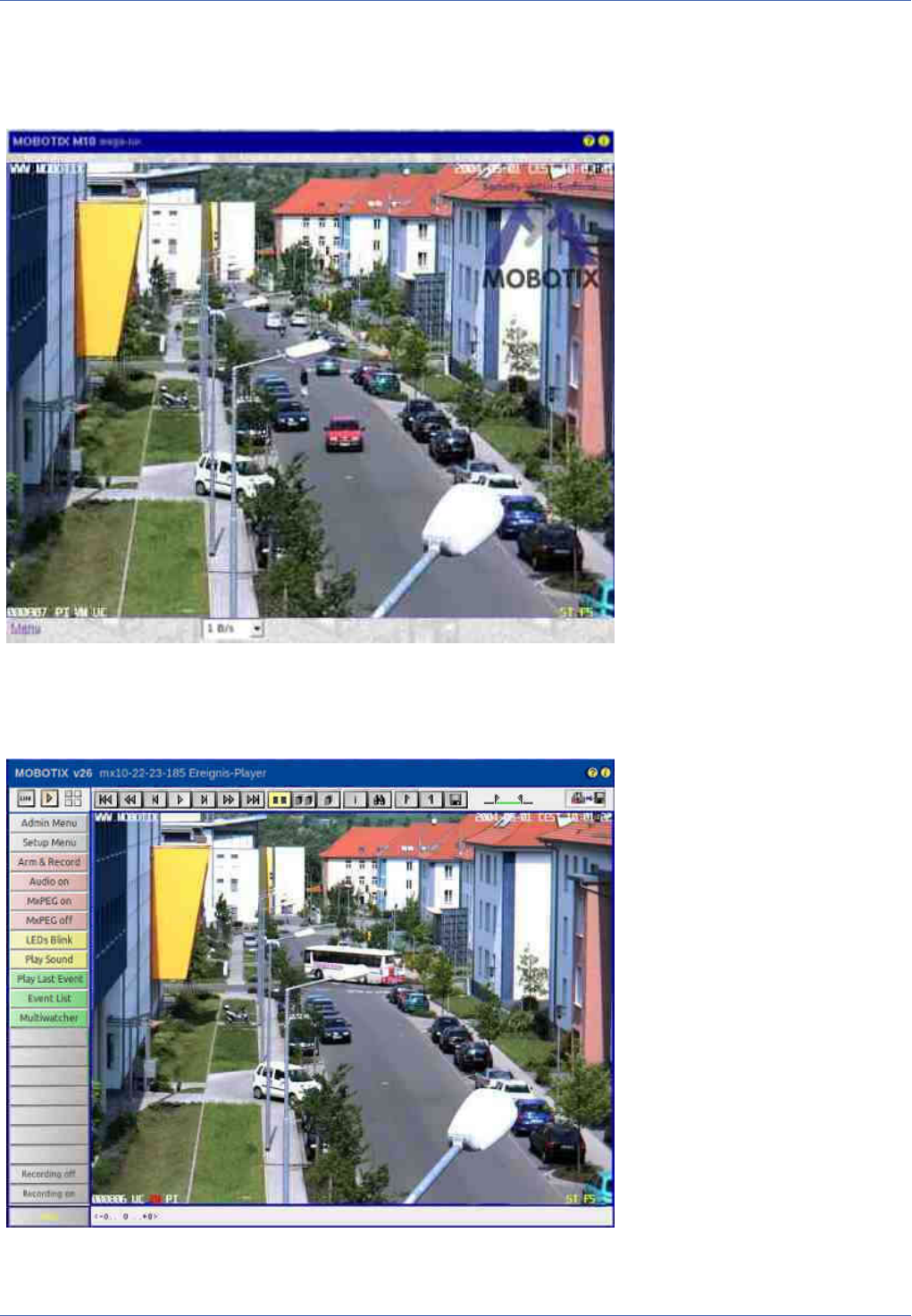
Screens of the MOBOTIX Camera
Reference
Screens of the MOBOTIX Camera
You can access the views of the MOBOTIX camera using the following buttons in the top left corner of the
browser:
n
:The Live Screen of the MOBOTIX Camera, p. 38
n
: The Player of the MOBOTIX Camera, p. 58
n
: The MultiView Screen of the MOBOTIX Camera, p. 69
To use a different start page as the Live view of the camera or to change the default language of the user inter-
face, open Admin Menu> Language and Start Page.
The Live Screen of the MOBOTIX Camera
The camera automatically opens the Live screen when you access the camera for the first time. Use this
screen to change image settings, to use the softbuttons, to open the Setup Menu or to access the password-
protected Admin Menu.
The Elements of the Live Screen
Hold your mouse over the elements of the user interface to see the bubble help. Click on the element to go
to the description.
Elements of the Title Bar
38 / 557
Name
Camera Model
Element
MOBOTIX M16
Description
Displays the model of the MOBOTIX camera.
Name
Camera Name
Element
mega-lux
Description
Shows the camera name as set in the Quick Installation wizard or in the Ethernet Interface dialog in
the Camera name field.
Name
Privacy Mode
Element
Description
Signals that the Privacy Mode is active. This mode prevents access to the camera in order to guar-
antee privacy. For additional information on this topic, see the Privacy Mode help page.
Name
Open Help
Element
Description
Opens the online help for the current screen or dialog. If no help page is available, the Table of Con-
tents page will be displayed.
Name
Camera Information
Element
Description
Displays information on the hardware, software and the most important settings of the camera.
Screens of the Camera
Name
Live
Reference
Screens of the MOBOTIX Camera
39 / 557

Reference
Screens of the MOBOTIX Camera
Element
Description
The Live screen of the MOBOTIX camera displays the current images of the camera.
Use the dropdown menus to access certain functions of the image controls and the camera admin-
istration or open the Setup Menu to see links to all image and event control dialogs.
The Admin Menu (password-protected) contains all dialogs for configuring the camera.
Name
Player
Element
Description
Use the Player screen to view and download the events stored in the internal or the external image
storage of the camera.
See also
The Player
Name
MultiView
Element
Description
Use the MultiView screen to combine several cameras in different patterns and to assign special func-
tions (highlighting, focus on alarm, ...) for the individual cameras.
See also
The MultiView Screen
Name
Guest
Element
40 / 557
Description
The Guest screen allows viewing the camera's live image, setting the frame rate within the preset lim-
its and accessing the Live screen by clicking on the Menu link at the bottom of the page.
See also
The Guest Screen
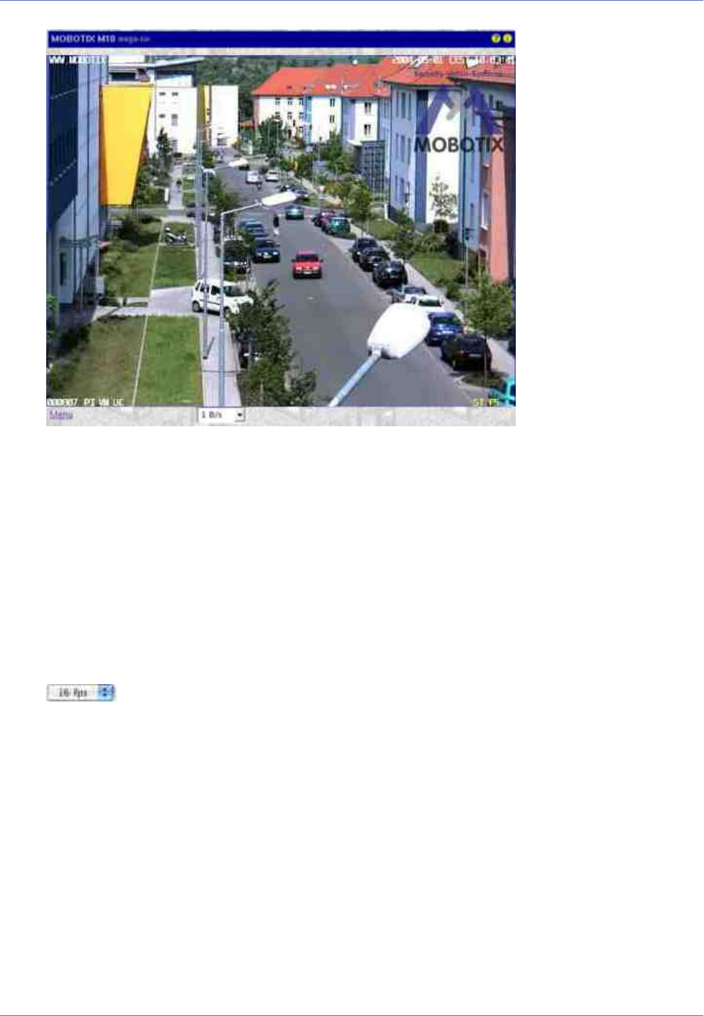
Image Control Elements
Name
Frame Rate
Element
Description
Select the desired frame rate for the Live screen.
Please note that the frame rate depends to a large degree on the bandwidth of the transmission path,
the selected resolution and the video codec used (MxPEG or Motion JPEG).
See also
The Best Frame Rate
Note
Reference
Screens of the MOBOTIX Camera
41 / 557

Reference
Screens of the MOBOTIX Camera
Depending on the camera model, the maximum frame rate in the browser may be
limited to 1fps.
Name
Function Selection
Element
Description
Use the image control functions to adjust the Live screen to your preferences:
Camera Selection
Select the right, the left or both image sensors, or the automatic Day/Night switch (only avail-
able in dual-lens models).
Display Mode
Depending on the camera model, you can use this option to display either different picture-in-
picture views or various views of corrected (i.e. undistorted) images (see General Image
Settings> Display Mode).
--vPTZ-----------------------
Installation
This command assists when configuring a camera for the first time.
1.
Depending on where the camera has been mounted, select Wall, Floor or Ceiling.
2.
Click with your mouse into the live image to turn the image into the desired direction.
3.
Depending on the camera model, select Set Focus or Set North.
Load View
Select the stored view you would like to see. A view is the combination of a direction and a
zoom factor.
Save View
Select the number of a view for which you would like to store the current direction and the
zoom factor.
Auto Mode
This feature allows automatically moving between stored positions.
n
Jump N/E/S/W (only for the Ceiling and Floor mounting types): Switches between the
North, East, South and West views. Corresponds to the Auto Move on softbutton.
n
Surround Clockwise (only for the Wall mounting type): Automatically moves through the
four defined views as defined by the Set Focus command. Corresponds to the Auto Move
on softbutton.
n
Views 1-15: Automatically loads the first 15 views that have been stored using the Save
View command, one after the other.
42 / 557

n
Off: Deactivates the Auto Mode. Corresponds to the Auto Move off softbutton.
Zoom
Allows setting a defined zoom level, defining a rectangular zoom area, activating/deactivating
the mouse wheel zoom (off by default) and can reset the pan/tilt features (corresponds to the
Center Pan softbutton).
--Recording---------------
Recording
Use this command to activate the recording features. In addition, you can select some pre-
defined settings for continuous recording and event recording in this section. The Add Video
Motion Window and Set Video Motion Window allows adding a new video motion window or set-
ting a new Video Motion Window by defining a rectangle in the live image by [Shift]-click, click,
respectively. In addition, you can activate full image and live image recording and show/hide
the Event and Action Symbols at the bottom of the image area.
--Image-----------------------
Image Size
Select the desired image size or draw a rectangle ([Shift]-click, click) in the camera's live image,
then use Define Custom Image Size to create an image with the dimensions of the rectangle.
Image Program
Highlight the desired image program.
Image Quality
Sets the level of detail that is used when reading the image sensor.
Brightness
Use this parameter if you would like to brighten up the entire image area (see Exposure
Settings).
Exposure Control
Select either the Visible Image Area or the Full Image Area exposure mode. The camera displays
more options if you have selected the Full Image Area exposure mode. For one thing, you can
use one of the predefined exposure windows to adjust the exposure control. Furthermore, you
can use a [Shift]-click, click to define a rectangle in the live image and to use it as the new
exposure window (Replace Exposure Window option) or to add it to the existing exposure win-
dows (Add Exposure Window option). In addition, you can show/hide the currently used meas-
urement windows in this exposure mode.
Color Saturation
Use this parameter to influence the color saturation of the image. The higher the saturation, the
more intense are the colors. The value -10 produces a gray-scale image (see Color Settings).
Backlight Correction
This parameter (like Brightness) also is used for adjusting the brightness of an image. However,
it only affects the darker portions of an image (Exposure Settings).
Sharpness
Use this parameter to set the desired value for sharpness control. A lower value results in a
Reference
Screens of the MOBOTIX Camera
43 / 557

Reference
Screens of the MOBOTIX Camera
smoother (less crisp) image (see General Image Settings).
JPEG Quality
Select the desired JPEG quality of the generated images.
Focusing Aid
This feature provides a visual aid for properly setting the focus of a MOBOTIX camera lens.
--Audio----------------------
Speaker Volume
This parameter sets the volume of the camera speaker.
Microphone Sensitivity
This parameter sets the sensitivity of the camera microphone.
--Web Technology------------
Browser
Select how the browser gets the images from the camera:
n
Internet Explorer: JavaScript (default), Java, ActiveX (only for Windows)
n
Netscape/Mozilla/Firefox: JavaScript, Server-Push (default), Java
--Configuration--------------
Managing Settings
Use this function to load the image factory defaults, restore the image settings from flash, and to
store the complete configuration (requires administrative access).
Note
Depending on the camera model, some of the listed features may not be available.
See also
The MxPEG ActiveX Plug-in for Internet Explorer
Name
Status Display
Element
Description
Displays the current status of the camera:
Black: Normal state of the camera.
Yellow blinking: The camera switches from one state to another (e.g. from the left to the right image
sensor).
44 / 557

Green: A process has been completed successfully (about one second).
Red: A process could not be completed successfully (about one second).
Other Elements
Name
Activate/Deactivate Pan/Zoom
Element
Description
This button allows or forbids vPTZ actions in all panorama and multi-window display modes. This
includes loading and saving of views.
Note
The Panorama and multi-window display modes may not be available on all camera
models.
Name
Preview Quality
Element
Description
This button turns the preview mode on or off. The availability of this button can be toggled in the Lan-
guage and Start Page dialog.
Name
High Quality
Element
Description
This button opens the High Quality image program.
Name
Store JPEG image
Element
Description
Reference
Screens of the MOBOTIX Camera
45 / 557

Reference
Screens of the MOBOTIX Camera
This button stores the current live image from the camera as a JPG file.
The Softbuttons
Name
Softbuttons
Element
Description
The softbuttons at the left-hand side of the screen execute certain functions, most of which can be
used by users with User level access.
If you have administrative access to the camera, you can assign new functions to existing softbuttons
by [Shift]-clicking the desired softbutton.
See also
n
Defining Softbuttons
n
Managing Users and Passwords
Name
Admin Menu
Element
Description
Opens the Administration menu of the MOBOTIX camera, allowing you to change the most important
system settings. You need a user name and password of an admins user group (Users and Passwords
dialog) to access this menu.
Name
Setup Menu
Element
Description
Opens the Setup menu with its dialogs for changing the image and event settings.
Name
Arm & Record
Element
Description
This wizard arms the camera, activates event recording, the camera microphone, the MxPEG video
codec, one Video Motion Detection window, the User Click event, the visual alarm and opens the
MultiView screen of the camera.
Name
Audio on
Element
Description
This Wizard activates the camera microphone and the audio output on the computer (only when using
46 / 557

Internet Explorer on Windows computers).
Name
MxPEG on
Element
Description
This softbutton activates the MxPEG video codec, which guarantees fast transmission of video and
audio data while using as little bandwidth as possible.
Name
MxPEG off
Element
Description
This softbutton deactivates the MxPEG video codec in order to produce JPEG images with the best pos-
sible quality. This is the preferred setting for webcam applications.
Name
Open Door
Element
Description
This softbutton triggers the door opener (door station only).
Name
Light ON/OFF
Element
Description
This softbutton button turns the lights on or off (door station only).
Name
UC Event ("User Click")
Element
Description
This softbutton triggers the User Click (UC) event.
Name
LEDs Blink
Element
Description
This softbutton will prompt the camera to blink with its camera LEDs for five seconds.
Name
Play Sound (on camera speaker)
Element
Description
This softbutton plays back a sound on the camera speaker. For additional information on recording
and using your own audio messages, see the Manage Audio Messages help page.
Reference
Screens of the MOBOTIX Camera
47 / 557

Reference
Screens of the MOBOTIX Camera
Name
Play Last Event
Element
Description
Plays back the last event recorded by the camera.
Name
Event List
Element
Description
Click on this button to display the Event List dialog. This dialog displays a list with the last 20 events
with the corresponding navigation links.
Click on one event link to show the corresponding event image in the player or select a date and time
to list the events of that point in time.
Name
Multiwatcher
Element
Description
The Multiwatcher displays the live/event images of this and other MOBOTIX cameras by means of a
"proxy camera". This means that only one camera needs to be accessible from outside of the network
and this camera allows you to see live images and event lists of this and other cameras within the net-
work.
Name
Zoom buttons
Element
Description
Use these buttons to control the digital zoom and the panning functions for moving the visible
area within a zoomed image:
1x Zoom
Switches the digital zoom off and returns to the regular camera view. This setting will deac-
tivate the Center Pan.
Zoom +
Increases the zoom level (i.e. enlarges the size of the displayed objects). From zoom level
[1.1x] on, clicking in the image will move the visible image area within the full image.
Zoom −
Reduces the zoom level (i.e. reduces the size of the displayed objects).
Center Pan
Moves the visible image area to the center of the full image, if zoom level [1.1x] or higher has
been activated.
48 / 557

See also
n
General Image Settings
n
The Best Frame Rate
Name
Display mode buttons
Element
Description
These buttons control specific image features of hemispheric cameras and are thus only avail-
able on these models:
Normal Image
Switches to the standard display mode that allows zooming and panning.
Panorama Image
Switches to the Panorama display mode.
Surround Image
Switches to the Surround display mode.
Auto Move on
Activates the N/E/S/W auto mode (Ceiling and Floor mounting types), which automatically moves
to the North, East, South and West views. If the mounting type has been set to Wall, this button
activates the Surround Clockwise auto mode, which automatically moves to the four views that
have been set using Set Focus.
Auto Move off
Deactivates the auto mode.
See also
General Image Settings
The Image Area
Name
Image Area
Element
Description
The image area shows the live images of the camera as well as logos, texts and symbols of the camera.
Reference
Screens of the MOBOTIX Camera
49 / 557

Reference
Screens of the MOBOTIX Camera
In addition, you may choose from the following options:
n
If the digital zoom has been activated, you can move the visible image area by clicking with the
mouse (panning). If you have activated the Mouse Wheel Zoom settings in the vPTZ Settings
dialog, you can use the mouse wheel to zoom in and out of the image.
n
If you are using MxManagementCenter, MxControlCenter, MxEasy or the MxPEG ActiveX Plug-in
for Internet Explorer, you can also use a joystick to control these features.
n
By using a [Shift]-click, click, you can define windows for several features of the camera (video
motion detection, obscuring image areas, ...) as described in the Graphically Entering Image
Areas topic.
Name
OnScreen Control
Element
Description
The OnScreen Control provides for convenient configuration of the Panorama, Double Panorama and
Panorama/Focus display modes (if available). This control allows panning, tilting and zooming the
camera's image to find the optimum image section for your purposes. Moreover, the trapezoid cor-
rection allows adjusting the skewed (vertical) lines on the image that are common for this type of lens.
Name
Logo
Element
Description
The functions for managing image files, logo definitions and creating image profiles will enable you to
use graphic files stored on the camera or from other URLs as logos with transparent areas or as water-
mark in every image of the camera. Using several logos will allow you to display these logos as ban-
ners at a definable interval.
If you are using Time Tables, you can also activate/deactivate the logos in a scheduled manner.
Name
Text Display
Element
50 / 557

WWW.MOBOTIX.COM
Description
Open the Text and Display Settings dialog to change the text that is displayed in the top left corner of
the image area.
Using variables and placeholders for dynamic image texts, you can display the current temperature
within the camera or text received via the serial interface in every image, for example.
Name
Date Display
Element
5/1/2015 CEST 10:01:22
Description
Open the Text and Display Settings dialog to change the date and time information that is displayed in
the top right corner of the image area.
Name
Event Symbols
Element
000807 UC VM PI
Description
Open the Text and Display Settings dialog to change the symbols that are displayed at the bottom of
the image area.
The event symbols in the lower left corner of the image area show the event number (in this case
000807) and the symbols for the activated sensors at the time of the recording. In this image, PI (PIR
sensor), VM (Video Motion Detection) and UC (User Click) had been activated.
If an event occurs, the corresponding symbol (e.g. VM) is displayed in red.
Name
Action Symbols
Element
REC FS
Description
Open the Text and Display Settings dialog to change the event symbols that are displayed at the bot-
tom of the image area.
The yellow symbols in the lower right corner of the image area show all actions that are active on the
camera. In this case, REC (Storage) and FS (File Server storage) are active.
If one of the actions is carried out, it is displayed in blue (e.g. ST); a failed action is shown in red (e.g.
FS).
Deactivated messages are shown in gray (e.g. EM in the detail view of the Action Group Overview
using Time Tables).
If a Time Table Profile has been selected in General Event Settings to control the Arming of the cam-
era, off is appended to the displayed action symbols if the time table has deactivated the camera's
arming switch.
Reference
Screens of the MOBOTIX Camera
51 / 557

Reference
Screens of the MOBOTIX Camera
Caution
If General Events > Arming has been set to off, event/action symbols and error
messages are not displayed in the image.
For failed actions, an error message will appear above the symbols. Open the Text and Display Settings
dialog to deactivate the error messages in the image.
See also
Abbreviations Used in the MOBOTIX Camera
Name
Archiving Status
Element
AS07%/42h
Description
Open the Text and Display Settings dialog to change the symbols that are displayed at the bottom of
the image area.
If Archiving is activated, the archive status symbol AS is displayed to the left of the action symbols.
This symbol shows two values that show the archiving status separated by /. The value to the left
shows the space used of the internal camera storage as a percentage value. The value to the right
shows the estimated time available to bridge an archive failure before data is lost, based on the avail-
able capacity of the internal camera storage. The time unit at the end shows either minutes, (m), hours
(h), days (d) or years (y).
If the camera detects a problem while archiving, the symbol color changes from yellow to red
(AS07%/42h).
Name
Error Icon
Element
Description
The camera displays the error icon in the upper left corner of the live image, if the camera detects a
possible hardware error. Please proceed as follows if this icon appears.
n
First, check the camera image (live image and recording) for abnormalities, such as image errors
or artifacts. Next, check the System Messages for critical messages (magenta text color) con-
cerning hardware defects and follow the instructions (if applicable).
n
Create a complete Camera Report of your MOBOTIX camera and the send the report to the
MOBOTIX support team (for further information, please go to the MOBOTIX website www.-
mobotix.com and open the Support section).
52 / 557

n
In order to deactivate the error icon in the meantime, you can add the following text in the con-
figuration of the MOBOTIX camera:
SECTION imageimprover_extend
error_symbol_live_display=0
ENDSECTION imageimprover_extend
Next, save the modified configuration in the permanent storage and reboot the camera.
The Image Programs of the MOBOTIX Camera
The image programs are selected using the pull-down lists above the camera's live image (Quick Controls) in
the browser. These programs adjust the relevant parameters of the MOBOTIX camera to the application scen-
ario; any basic configuration should thus begin by selecting one of the image programs.
In a webcam scenario, for example, moving objects can become blurred when illumination fades, i.e. the
camera can use longer exposure times when the scene gets darker so as to provide images with good expos-
ure for as long as possible.
If fast images are required, the camera should use a maximum (longest) exposure time of 1/60s in order to
obtain a high frame rate. Likewise, the camera should use the MxPEG codec instead of the JPEG codec, since
MxPEG will only transfer the changed portions of the image, resulting in higher image rates and reduced net-
work loads.
Note
In order to check or change the settings performed by the different image programs, open
the corresponding dialogs in the Setup Menu.
Selectable Image Programs of the MOBOTIX Camera
n
Fast:
This image program prepares the camera for delivering live images as fast as possible. This means that
the image quality is set to Fast, the camera will use the MxPEG video codec, JPEG quality is set to
40% and the maximum exposure time is set to 1/60s. Please note that the highest image rates will
only be reached using either Internet Explorer on Windows computers with installed MxPEG ActiveX
plug-in or when using MxManagementCenter, MxControlCenter or MxEasy.
n
Security Application:
This is the preferred image program for security applications. It uses Normal image quality, the
MxPEG codec, a JPEG quality of 60%, a maximum exposure time of 1/5s and the exposure pro-
gram -2 to avoid blurred rendering of moving objects as much as possible when the illumination
decreases.
n
Quality:
This image program constitutes a good compromise between high-quality and fast images as illu-
mination decreases. It uses Normal image quality, the MxPEG codec, a JPEG quality of 60% and a
maximum exposure time of 1/5s.
Reference
Screens of the MOBOTIX Camera
53 / 557

Reference
Screens of the MOBOTIX Camera
n
High Quality:
This image program puts higher priority on high image quality even when illumination decreases. It
uses Fast image quality, the MxPEG codec, JPEG quality is set to 80% and the maximum exposure
time is set to 1/5s. By using the +1 image program, moving objects may shown a little blurriness
when illumination gets lower, but image quality is better.
n
Webcam:
Image quality is the key factor for webcam applications. This image program hence uses High image
quality, the JPEG codec for creating full JPEG images with a JPEG quality of 80%. The other settings
(Night Improvement: Off, maximum exposure time: 1/1s, minimum average brightness Off and the
image program +2) allow generating sufficiently bright images for as long as possible; even though
the longer exposure times may lead to moving objects that are blurred.
The MxPEG ActiveX Plug-in for Internet Explorer
If you are using Internet Explorer (from version 5.5) on a Windows computer (from Windows 2000), you can
use the MxPEG ActiveX plug-in for viewing the live camera images. This plug-in allows you to combine the
advantages of MxPEG with the browser-based user interface:
n
Lower bandwidth requirements due to MxPEG video compression
n
Smooth movements in the video stream thanks to high frame rates
n
Audio channel of the camera available on the local computer
n
Additional scaling functions in the browser
n
Panning (moving the visible image area within the full image) with activated digital zoom by clicking
in the image.
Note
If fast movements occur in the image, you may see tiles in the image if MxPEG is activated.
If you prefer better image quality, you should deactivate MxPEG as described in High Res-
olution and Quality.
See also
MxManagementCenter, MxControlCenter and MxEasy
Prerequisites for Using the MxPEG ActiveX Plug-in
Make sure that the following prerequisites are fulfilled if you intend to use the MxPEG ActiveX plug-in:
n
MOBOTIX camera model IT or higher
n
Windows computer from Windows 2000
n
Installed Internet Explorer from Version 5.5
n
Administrator or Power User access on the local computer (for installing the plug-in)
54 / 557

n
Suitable security settings in Internet Explorer to install and to execute ActiveX plug-ins. In Internet
Explorer, open Tools> Internet Options> Security (tab) and make sure that the following settings are
active for the current security level:
n
Execute ActiveX controls that are safe for scripting: Activate or Prompt
n
Execute ActiveX controls and plug-ins: Activate or Prompt
n
Download signed ActiveX controls: Activate or Prompt
n
Access to the camera with a user or admin login as described in Managing Users and Pass-
words.
Installing and Running the MxPEG ActiveX Plug-in
Proceed as outlined in the following:
1.
Start Internet Explorer and enter the address of a MOBOTIX camera (from software version 2.0).
2.
Open the image controls, select the Browser option and set ActiveX as value.
3.
You will be asked if you would like to accept the installation of the signed ActiveX plug-in. Click OK to
install the plug-in.
4.
Click on the MxPEG on button on the user interface or activate MxPEG in the JPEG Settings dialog to
use the advantages of MxPEG video encoding.
Notes
n
Right-click in the image area to check if the ActiveX plug-in is running. You should
now see the context menu explained in the Options of the MxPEG ActiveX Plug-in
section, not the standard context menu of Internet Explorer.
n
If you have completely closed Internet Explorer, you will need to restart the plug-in
the next time you would like to access the camera by again selecting the Browser
and ActiveX options in the image controls.
Options of the MxPEG ActiveX Plug-in
If the MxPEG ActiveX plug-in has been installed, right-clicking the image will display a context menu with the
following options:
Option
Zoom
Values
1x/ 2x/ 4x Center Pan
Description
Use these options to control the digital zoom and the panning functions for moving the visible section
within a zoomed image. The functions are the same as for the zoom buttons.
Option
Default View
Values
Reference
Screens of the MOBOTIX Camera
55 / 557

Reference
Screens of the MOBOTIX Camera
Set Default View / Load Default View
Description
Use these options to control the functions for moving the visible section within a zoomed image (pan-
ning). The functions are the same as for the zoom buttons.
Option
Scale image
Values
0.5x/ 1x/ 2x
Description
Scales the image of the ActiveX plug-in to the desired size.
Option
Audio from camera
Values
−
Description
Activate this option to listen to the audio channel of the camera.
If the camera's microphone is deactivated, this entry is shown in gray and cannot be selected. If this is
the case, open the Speaker and Microphone dialog and activate the microphone.
Option
Audio to camera
Values
−
Description
Activate this option to listen to the audio channel of the camera.
If the camera speaker is deactivated, open the Speaker and Microphone dialog and activate the
speaker.
Option
Change access level
Values
−
Description
Changes the access level used by the ActiveX plug-in to access the camera. User access can use all func-
tions of the ActiveX plug-in, Guest disables the audio functions and the zoom controls.
If a password has been assigned for the user or the guest level, the plug-in will again ask for login
credentials to access the camera. This authorization is required for security reasons and cannot be cir-
cumvented.
Option
About MxPEG ActiveX
Values
56 / 557

−
Description
Displays information about the version of the MxPEG ActiveX plug-in.
The Best Frame Rate
Depending on the camera application (e.g. bandwidth of the data connection), the frame rate requirements
may vary greatly.
Fast Images
For security applications that require fast images, you should use a Windows computer (from Windows XP)
and Internet Explorer (from version 6) in conjunction with the MxPEG ActiveX plug-in, MxManagementCenter,
MxControlCenter or MxEasy for viewing the live camera images. Furthermore, you should provide a data link
with sufficient bandwidth for the camera's images.
Set the following parameters to the values listed below:
n
Use the image controls to set these parameters:
n
Resolution: 320x240
n
JPEG Quality: 80%
n
Sharpness: 0-2
n
Right-click in the image area (this will show the context menu described in Options of the MxPEG Act-
iveX plug-in) and select the Scale image> 2x option.
n
Select a Frame rate of 25fps.
n
Click on the MxPEG on button on the user interface or activate MxPEG in the JPEG Settings dialog.
High Resolution and Quality
If the frame rate is not the most important criterion of an application, you can set the focus on image qual-
ity:
n
Use the image controls to set these parameters:
n
Resolution: 640x480 or 1280x960
n
JPEG Quality: 70%
n
Sharpness: 4 (default)
n
Click on the MxPEG off button on the user interface or deactivate MxPEG in the JPEG Settings dialog.
n
Adjust the frame rate to the other factors of the application (especially the available bandwidth) and to
your preferences:
The Focusing Aid of the Camera
This feature provides a visual aid for properly setting the focus of a MOBOTIX camera lens. The focusing aid
is especially useful when settings up a lens of a MOBOTIX D16, D26 or when exchanging a MOBOTIX standard
lens for a tele lens of a MOBOTIX M26, for example.
To activate the focusing aid, select the Focusing Aid Quick Control and set the value to Enable; the focusing
aid will be displayed in the live window. The camera displays a rectangle with a white and black border. This
is the image area used by the camera to determine the best focus of the lens (focusing window). The focusing
window can be tuned to the area to be focused by using Shift-Click. In addition, the camera shows a green
bar. This bar shows the best focus value obtained in the focusing window so far. When changing the focus of
Reference
Screens of the MOBOTIX Camera
57 / 557

Reference
Screens of the MOBOTIX Camera
the lens, the green bar grows as the focus improves. If the focus decreases again, a red bar appears. The focus
of the lens is set to the best value if the red bar covers as little as possible of the green bar or disappears at
all.
Notes
n
Under some circumstances it is not possible to make the red bar vanish completely.
The focus of the lens is nevertheless set to the best value if the red bar covers as
little of the green bar as possible.
n
For best results when setting image sharpness you should use full image display
mode, high image quality and 1x Zoom!
n
In addition to the visual focusing aid, you can activate the audio output: The pitch
of the tone corresponds to the level of sharpness. This can help you to focus the
lens without having to see the camera image.
Store Configuration
Using the controls of the Live screen to adjust the camera configuration will keep these changes until the
next reboot of the camera, it will not automatically store them permanently. If you have administrative
access to the camera, you should store the current configuration into flash memory.
The Player of the MOBOTIX Camera
Open the Player to play back the recorded events and image sequences of the camera, to open the event list
and to download images in a package with the offline player.
The Elements of the Player Screen
Hold your mouse over the elements of the user interface to see the bubble help. Click on the element to go
to the description.
58 / 557

Elements of the Title Bar
Name
Camera Model
Element
MOBOTIX M16
Description
Displays the model of the MOBOTIX camera.
Name
Camera Name
Element
mega-lux
Description
Shows the camera name as set in the Quick Installation wizard or in the Ethernet Interface dialog in
the Camera name field.
Name
Open Help
Element
Description
Opens the online help for the current screen or dialog. If no help page is available, the Table of Con-
tents page will be displayed.
Name
Camera Information
Element
Description
Displays information on the hardware, software and the most important settings of the camera.
Screens of the Camera
Name
Live
Element
Description
The Live screen of the MOBOTIX camera displays the current images of the camera.
Reference
Screens of the MOBOTIX Camera
59 / 557

Reference
Screens of the MOBOTIX Camera
Use the dropdown menus to access certain functions of the image controls and the camera admin-
istration or open the Setup Menu to see links to all image and event control dialogs.
The Admin Menu (password-protected) contains all dialogs for configuring the camera.
See also
The Live View
Name
Player
Element
Description
Use the Player screen to view and download the events stored in the internal or the external image
storage of the camera.
If you click on again in the Player and Storage on External File Server / Flash Device is activated,
the camera displays a list containing the current storage size of the Internal Recorder and of any cam-
eras that are storing their images on the same file server into the same directory.
Name
MultiView
Element
Description
Use the MultiView screen to combine several cameras in different patterns and to assign special func-
tions (highlighting, focus on alarm, ...) for the individual cameras.
See also
The MultiView Screen
Name
Guest
Element
60 / 557

Description
The Guest screen allows viewing the camera's live image, setting the frame rate within the preset lim-
its and accessing the Live screen by clicking on the Menu link at the bottom of the page.
See also
The Guest Screen
Elements of the Player Controls
Name
First event
Element
Description
Displays the first event that is stored.
Name
Fast Backward
Element
Description
Reference
Screens of the MOBOTIX Camera
61 / 557

Reference
Screens of the MOBOTIX Camera
Starts fast rewind from the current image in endless loop mode. Shows only the event images, all
events including event story or one event story only, depending on the settings of the Event Story but-
tons.
Name
One frame backward
Element
Description
Shows the previous event image or the previous image of an event story. Shows only the event
images, all events including event story or one event story only, depending on the settings of the
Event Story buttons. If the first image has been reached, the next click will show the last image.
Name
Play
Element
Description
Starts playing back the images in endless loop mode. Shows only the event images, all events includ-
ing event story or one event story only, depending on the settings of the Event Story buttons.
Name
Stop
Element
Description
Stops an active playback in progress that had been started using the Play , Fast Forward
or Fast Rewind buttons.
Name
One frame forward
Element
Description
Shows the next event image or the next image of an event story, depending on the settings of the
Event Story buttons. If the last image has been reached, the next click will show the first image.
Name
Fast forward
Element
62 / 557

Description
Starts fast playback of the images in endless loop mode. Shows only the event images, all events
including event story or one event story only, depending on the settings of the Event Story buttons.
Name
Last event
Element
Description
Displays the last event that is stored.
Name
Show image information
Element
Description
Displays the information of the current image.
Name
Event List
Element
Description
Shows the Event List that allows you to pull up specific events in the camera Player.
In this dialog, click on the Download link to download the desired events with an integrated event
player. You can also set the range (start and end points) of the events you would like to download.
Click on Set Event Range to display the size of the packed archive file together with other inform-
ation in the upper half of the dialog.
Notes
n
If you opened the Download dialog using the Event Download softbutton, the
download range is always preset to all sequences.
n
Note that the number of sequences to download is limited to 25,000.
n
To display the content of the downloaded .tar archive file, you can use e.g.
WinZip, StuffIt or PowerArchiver.
Name
Set the beginning and the end of the download range.
Element
Reference
Screens of the MOBOTIX Camera
63 / 557

Reference
Screens of the MOBOTIX Camera
Description
Select the desired range you would like to download using these buttons. Use the Set Download
Range Start button to set the start and the Set Download Range End button to set the
end of the download range to the image that is currently displayed. [Shift]-click on one of these but-
tons to navigate to the corresponding image.
Once you have defined the range, the indicator shows the position of the current image:
Current image is before the selected download range.
Current image is within the selected download range.
Current image is after the selected download range.
Click on the Event Download button to open the Download dialog; the selected range is
already entered in the corresponding fields.
Name
Event Download
Element
Description
Shows the Download dialog, which allows saving the recorded events of the camera as a TAR archive
or MxPEG stream to a computer or a mobile storage device (USB keydrive, SD card, etc.).
If the beginning and the end of the download range have been set using the corresponding buttons
(see above), this range has been preselected in the Download dialog.
Name
Preview Quality
Element
Description
This button turns the preview mode on or off. The availability of this button can be toggled in the Lan-
guage and Start Page dialog.
The Event Story Buttons
64 / 557

Click on these buttons of the Player controls to change the manner in which the Player plays back event stor-
ies (i.e. pre-alarm images, the event image itself and the post-alarm images). The Status bar indicates the
image of an event story that is currently displayed.
In order to change the settings for recording event stories, open the General Event Settings dialog. This dia-
log will also allow you to specify if you would like to save an event story with every event or only when spe-
cific events occur.
Name
Events only (no story)
Element
Description
(Default) Only shows the event images starting from the current image; pre- and post-alarm images
are skipped.
Name
With event story
Element
Description
Shows all images (pre-alarm, event and post-alarm images) of all events starting from the current
image.
Name
One event story only
Element
Description
Shows all images (pre-alarm, event and post-alarm images) of the current event in endless loop mode.
The Softbuttons
Name
Softbuttons
Element
Description
The softbuttons at the left-hand side of the screen execute certain functions, most of which can be
used by users with User level access.
If you have administrative access to the camera, you can assign new functions to existing softbuttons
by [Shift]-clicking the desired softbutton.
Reference
Screens of the MOBOTIX Camera
65 / 557

Reference
Screens of the MOBOTIX Camera
See also
n
Defining Softbuttons
n
Managing Users and Passwords
Name
Admin Menu
Element
Description
Opens the Administration menu of the MOBOTIX camera, allowing you to change the most important
system settings. You need a user name and password of an admins user group (Users and Passwords
dialog) to access this menu.
Name
Setup Menu
Element
Description
Opens the Setup menu with its dialogs for changing the image and event settings.
Name
Arm & Record
Element
Description
This wizard arms the camera, activates event recording, the camera microphone, the MxPEG video
codec, one Video Motion Detection window, the User Click event, the visual alarm and opens the
MultiView screen of the camera.
Name
Audio on
Element
Description
This Wizard activates the camera microphone and the audio output on the computer (only when using
Internet Explorer on Windows computers).
Name
MxPEG on (MxPEG on)
Element
Description
This softbutton activates the MxPEG video codec, which guarantees fast transmission of video and
audio data while using as little bandwidth as possible.
Name
MxPEG off (MxPEG off)
Element
Description
66 / 557

This softbutton deactivates the MxPEG video codec in order to produce JPEG images with the best pos-
sible quality. This is the preferred setting for webcam applications.
Name
LEDs Blink
Element
Description
This softbutton will prompt the camera to blink with its camera LEDs for five seconds.
Name
Play Sound (on camera speaker)
Element
Description
This softbutton plays back a sound on the camera speaker. For additional information on recording
and using your own audio messages, see the Manage Audio Messages help page.
Name
Play Last Event
Element
Description
Plays back the last event recorded by the camera.
Name
Event List
Element
Description
Click on this button to display the Event List dialog. This dialog displays a list with the last 20 events
with the corresponding navigation links.
Click on one event link to show the corresponding event image in the player or select a date and time
to list the events of that point in time.
Name
Multiwatcher
Element
Description
The Multiwatcher displays the live/event images of this and other MOBOTIX cameras by means of a
"proxy camera". This means that only one camera needs to be accessible from outside of the network
and this camera allows you to see live images and event lists of this and other cameras within the net-
work.
Name
Recording off
Element
Description
Deactivates the recording features of the MOBOTIX camera.
Name
Reference
Screens of the MOBOTIX Camera
67 / 557
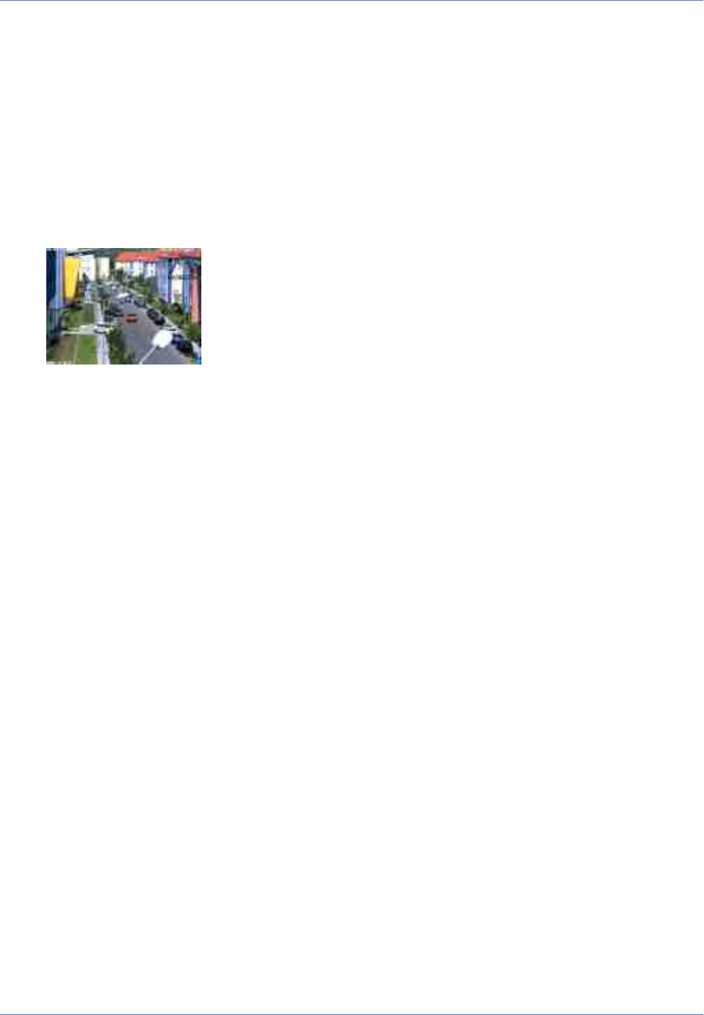
Reference
Screens of the MOBOTIX Camera
Recording on
Element
Description
Activates the recording features of the MOBOTIX camera.
The Image Area
Name
Image Area
Element
Description
The image area shows the event images of the current camera.
Click into the image to open the information window for the current image.
Name
Text Display
Element
WWW.MOBOTIX.COM
Description
Shows the text that had been defined in the Text and Display Settings dialog at the time of the record-
ing.
Name
Date Display
Element
5/1/2015 CEST 10:01:22
Description
Displays the date and time information of the current image.
Name
Event Symbols
Element
000806 UC VM PI
Description
Shows the event number (in this case 000806) and the symbols for the activated sensors at the time of
the recording. In this image, the UC (User Click), VM (Video Motion) and PI (PIR sensor) had been
68 / 557

activated.
Since a video motion window triggered the recording, the VM symbol is shown in red.
Name
Action Symbols
Element
REC FS
Description
This shows the symbols of the actions that had been active at the time of the recording. In this case,
REC (Storage) and FS (File Server storage) had been active.
If one of the actions is carried out, it is displayed in blue (e.g. REC in every last image of an event
story); a failed action is shown in red (z. B. FS).
Name
Status Bar
Element
<-1..0..+2>
Description
The Status bar shows, whether or not an event story had been stored for the current event image. In
this case, one pre-alarm image (-1) and two post-alarm images (+2) had been stored. The number in
the middle (0) shows the current image's position (in this case, the event image itself).
See also
The Event Story Buttons
Store Configuration
If you have made adjustments to e.g. the softbuttons (using [Shift]-click), the camera will keep these changes
until the next reboot, but it will not automatically store them permanently. If you have administrative access
to the camera, you should store the current configuration into flash memory.
The MultiView Screen of the MOBOTIX Camera
The MultiView screen provides a way of grouping several cameras in different patterns or shows one camera
with its latest events.
The Elements of the MultiView Screen
Hold your mouse over the elements of the user interface to see the bubble help. Click on the element to go
to the description.
Reference
Screens of the MOBOTIX Camera
69 / 557

Reference
Screens of the MOBOTIX Camera
Elements of the Title Bar
Name
Camera Model
Element
MOBOTIX M16
Description
Displays the model of the MOBOTIX camera.
Name
Camera Name
Element
mega-lux
Description
Shows the camera name as set in the Quick Installation wizard or in the Ethernet Interface dialog in
the Camera name field.
Name
MultiView Screen Name
Element
Quad
Description
Displays the name of the current MultiView as set in the MultiView Screens dialog.
Name
Open Help
70 / 557

Element
Description
Opens the online help for the current screen or dialog. If no help page is available, the Table of Con-
tents page will be displayed.
Name
Camera Information
Element
Description
Displays information on the hardware, software and the most important settings of the camera.
Screens of the Camera
Name
Live
Element
Description
The Live screen of the MOBOTIX camera displays the current images of the camera.
Use the dropdown menus to access certain functions of the image controls and the camera admin-
istration or open the Setup Menu to see links to all image and event control dialogs.
The Admin Menu (password-protected) contains all dialogs for configuring the camera.
See also
The Live View
Name
Player
Element
Description
Use the Player screen to view and download the events stored in the internal or the external image
storage of the camera.
See also
The Player
Name
MultiView
Reference
Screens of the MOBOTIX Camera
71 / 557

Reference
Screens of the MOBOTIX Camera
Element
Description
Use the MultiView screen to combine several cameras in different patterns and to assign special func-
tions (highlighting, focus on alarm, ...) for the individual cameras.
Name
Guest
Element
Description
The Guest screen allows viewing the camera's live image, setting the frame rate within the preset lim-
its and accessing the Live screen by clicking on the Menu link at the bottom of the page.
See also
The Guest Screen
Image Control Elements
Name
Stop / Restart
Element
72 / 557

Description
Use these buttons to stop or restart the display of images from all cameras shown on this MultiView
screen.
Name
Select MultiView screen
Element
Description
Select the desired MultiView screen from the pulldown list.
Name
Define new screen
Element
Description
Click on this link to define a new MultiView screen.
The Softbuttons
Name
Softbuttons
Element
Description
The softbuttons at the left-hand side of the screen execute certain functions, most of which can be
used by users with User level access.
If you have administrative access to the camera, you can assign new functions to existing softbuttons
by [Shift]-clicking the desired softbutton.
See also
n
Defining Softbuttons
n
Managing Users and Passwords
Name
Admin Menu
Element
Description
Opens the Administration menu of the MOBOTIX camera, allowing you to change the most important
system settings. You need a user name and password of an admins user group (Users and Passwords
dialog) to access this menu.
Name
Reference
Screens of the MOBOTIX Camera
73 / 557

Reference
Screens of the MOBOTIX Camera
Setup Menu
Element
Description
Opens the Setup menu with its dialogs for changing the image and event settings.
Name
Arm & Record
Element
Description
This wizard arms the camera, activates event recording, the camera microphone, the MxPEG video
codec, one Video Motion Detection window, the User Click event, the visual alarm and opens the
MultiView screen of the camera.
Name
Audio on
Element
Description
This Wizard activates the camera microphone and the audio output on the computer (only when using
Internet Explorer on Windows computers).
Name
MxPEG on (MxPEG on)
Element
Description
This softbutton activates the MxPEG video codec, which guarantees fast transmission of video and
audio data while using as little bandwidth as possible.
Name
MxPEG off (MxPEG off)
Element
Description
This softbutton deactivates the MxPEG video codec in order to produce JPEG images with the best pos-
sible quality. This is the preferred setting for webcam applications.
Name
Open Door
Element
Description
This softbutton triggers the door opener (door station only).
Name
Light ON/OFF
Element
Description
This softbutton button turns the lights on or off (door station only).
74 / 557

Name
UC Event ("User Click")
Element
Description
This softbutton triggers the User Click (UC) event.
Name
LEDs Blink
Element
Description
This softbutton will prompt the camera to blink with its camera LEDs for five seconds.
Name
Play Sound (on camera speaker)
Element
Description
This softbutton plays back a sound on the camera speaker. For additional information on recording
and using your own audio messages, see the Manage Audio Messages help page.
Name
Play Last Event
Element
Description
Plays back the last event recorded by the camera.
Name
Event List
Element
Description
Click on this button to display the Event List dialog. This dialog displays a list with the last 20 events
with the corresponding navigation links.
Click on one event link to show the corresponding event image in the player or select a date and time
to list the events of that point in time.
Name
Multiwatcher
Element
Description
The Multiwatcher displays the live/event images of this and other MOBOTIX cameras by means of a
"proxy camera". This means that only one camera needs to be accessible from outside of the network
and this camera allows you to see live images and event lists of this and other cameras within the net-
work.
Name
Zoom buttons
Element
Reference
Screens of the MOBOTIX Camera
75 / 557

Reference
Screens of the MOBOTIX Camera
Description
Use these buttons to control the digital zoom and the panning functions for moving the visible
area within a zoomed image:
1x Zoom
Switches the digital zoom off and returns to the regular camera view. This setting will deac-
tivate the Center Pan.
Zoom +
Increases the zoom level (i.e. enlarges the size of the displayed objects). From zoom level
[1.1x] on, clicking in the image will move the visible image area within the full image.
Zoom −
Reduces the zoom level (i.e. reduces the size of the displayed objects).
Center Pan
Moves the visible image area to the center of the full image, if zoom level [1.1x] or higher has
been activated.
See also
n
General Image Settings
n
The Best Frame Rate
Name
Display mode buttons
Element
Description
These buttons control specific image features of hemispheric cameras and are thus only avail-
able on these models:
Normal Image
Switches to the standard display mode that allows zooming and panning.
Panorama Image
Switches to the Panorama display mode.
Surround Image
Switches to the Surround display mode.
Auto Move on
Activates the N/E/S/W auto mode (Ceiling and Floor mounting types), which automatically moves
to the North, East, South and West views. If the mounting type has been set to Wall, this button
activates the Surround Clockwise auto mode, which automatically moves to the four views that
have been set using Set Focus.
Auto Move off
Deactivates the auto mode.
76 / 557

See also
General Image Settings
The Image Area
Name
Image Area
Element
Description
The image area shows the images of one or more cameras, as defined in the Configure MultiView
Screens dialog. In addition, you may choose from the following options:
n
[Shift]-click on one of the image areas to open the Configure MultiView Image Area dialog for
this area.
n
Clicking one of the image areas will open the camera, provided that it actually is a MOBOTIX
camera.
See also
Multi View Screens
Store Configuration
Changes to the MultiView screen that you performed in the MultiView Screens dialog or by [Shift]-clicking
one of the image areas will only be valid until the next reboot of the camera. If you have administrative
access to the camera, you should store the current configuration into flash memory.
The Multiwatcher
The Multiwatcher screen offers a user-friendly and configurable view of several cameras that is actually run-
ning on one camera only. This approach allows accessing one camera using a DynDNS-capable router, for
example, to see all other cameras behind the router/firewall.
The cameras are displayed in a table layout, with one camera occupying one column. Each column consists
of four rows, which display the following for each camera (top to bottom):
n
Name of the camera
n
Preview image of the live image
n
The last stored alarm image as preview image
n
An alarm list with the last alarm that triggered an alarm recording
When you are accessing one of the displayed cameras, the camera is actually accessed by the camera running
the Multiwatcher (proxy camera). This is always the camera that is running the Multiwatcher. The Multi-
watcher screen on the proxy camera hence even works if the corresponding camera is running in a network
Reference
Screens of the MOBOTIX Camera
77 / 557

Reference
Screens of the MOBOTIX Camera
behind a firewall or router. The only requirement is that the proxy camera has to be accessible from the out-
side, i.e. the firewall has to be configured accordingly. Once this has been set up, you can access the camera
from the outside and from within the network, since the proxy camera collects the live and alarm images
from the other internal cameras.
It is also possible to store authentication information (user name and password) for each camera in the proxy
camera, allowing you to show password-protected cameras without entering the required passwords every
time you open the Multiwatcher screen. A one-time authentication of the user at the proxy camera when
accessing the Multiwatcher screen is sufficient.
Note
Make sure that Zeroconf has been activated on all cameras (Ethernet Interface> Zero-
conf), since the proxy camera uses this method to find all available cameras. For addi-
tional information on Zeroconf, open the Ethernet Interface help page.
Information on the Screen
The Live Image
The live image of each camera is shown as preview image (160x120 pixels) and is updated periodically. You
can select the update interval in the Multiwatcher Configuration dialog. Click on the image to see the image
in its original size in a separate window.
The Last Stored Alarm Image
The last stored alarm of each camera is shown as preview image (160x120 pixels). Click on the image to see
the alarm image in its original size in a separate window.
When an initial alarm occurs (i.e. an alarm that triggers a recording), the camera automatically updates the
image.
Note
If an event occurs that has been activated in the Recording dialog in the Start Recording
list and in the Retrigger Recording or the Stop Recording list, the camera will not trigger
a new recording. Such an event will not trigger an initial alarm and will hence not appear
in the alarm list.
The Alarm List
The alarm list contains all information on the latest alarm images that have been recorded by an initial
alarm. Clicking on an entry in the list displays the alarm image in its original size in a separate window.
The camera automatically updates the list every time it detects an initial alarm. New list entries are briefly
shown in red. If you have activated the Notification in the Multiwatcher Configuration dialog, the alarm
will stay red until the user acknowledges the alarm by clicking on it.
If Audio Notification has been activated (button reads On) and the browser supports sounds, the camera will
play an alarm sound. To deactivate the feature temporarily, click on the button On (the button changes to
Off).
Configuring Multiwatcher Screens
78 / 557

You can define several Multiwatcher screens with different cameras, with each page showing a different set of
cameras. To change between screens, select a different Multiwatcher screen in the Screen dropdown box.
If you would like to configure the current screen, open the corresponding configuration dialog by clicking on
the Configure Screen link.
After changing a Multiwatcher screen, the Store button appears beneath the alarm list. Click on this button
to permanently store the entire configuration in the camera's Flash memory.
More Features
Setting the Screen as Start Page
The Language and Start Page dialog allows setting the Multiwatcher as Start Page. This page will be dis-
played automatically when a browser connects to the camera.
Playing Sounds on Alarms
If the ActiveX control is used to display the camera's live and event images (only Internet Explorer on Win-
dows), the plugin will automatically play a sound if one of the cameras in a MultiView layout has detected an
event. Clicking on the corresponding button will deactivate or activate this feature.
Stopping the Multiwatcher Screen
The Stop button stops the camera process that updates the camera images. To restart the Multiwatcher
screen, simply click on the Start button.
Storing the Configuration
If you have changed the Multiwatcher screen in the Multiwatcher Configuration dialog, you can save the
entire configuration of the camera by clicking on the Store button.
Configuring the Multiwatcher
Open the Multiwatcher Configuration page by clicking on the Configure Screen link in any Multiwatcher
screen.
You can use the configuration dialog to change the screen (add new cameras, change settings, etc.) or you
can rename or delete it. In addition, you can create new screens.
Note
In order to add new cameras to a screen, the cameras need to be registered in this camera.
Click on the Register Other Cameras link and add a new camera manually or have the
camera scan the local subnet for additional MOBOTIX cameras.
Changing the Configuration
The configuration dialog is structured similar to the corresponding Multiwatcher screen. Every camera occu-
pies one column in the table. The rows contain the parameters that can be configured.
To change the name of a screen, simply enter the desired name in the Screen text field. You can only use let-
ters, digits, blanks, underscore ("_") and hyphen.
If you have defined more than one screen, you can set the current screen as the default screen that appears
when clicking on the Multiwatcher button. Activate the Set as default screen checkbox to achieve this.
Reference
Screens of the MOBOTIX Camera
79 / 557

Reference
Screens of the MOBOTIX Camera
You can change the following settings for each camera:
Parameter Description
Camera Select the camera you would like to display from the dropdown box.
The Preview image shows the live image of the selected camera.
Refresh Rate Set the desired refresh rate for the live image in this dropdown box.
The refresh rate can be set to 1 second and up.
Notification Switch the sound notification and the visual hint when a new initial alarm occurs on or off.
To add new cameras to the screen, click on the Add button. The camera adds a new column to the table,
allowing you to select a new camera and to configure it.
To delete a camera from the screen, click on the Delete button of the corresponding column.
Click on the OK button to activate your settings and to save them until the camera is rebooted. Click on
Cancel to return to the Multiwatcher screen without changing anything.
Creating a New Screen
Click on the New Screen link to create a new screen. The camera opens a new configuration dialog. Change
the preset name and then add new cameras to the screen.
Deleting a Screen
If you have defined more than one screen, you can delete the current screen by clicking on the red Delete
button at the top of the configuration dialog behind the name of the screen.
Storing a Screen
Click on OK to store the changed Multiwatcher screen and to return to the Multiwatcher view. If the Multi-
watcher screen has changed, you can store the screen and the complete configuration of the camera.
Click on the Cancel button to discard all changes to the configuration.
The Guest Screen of the MOBOTIX Camera
The Guest screen of the camera is a restricted screen without any access to administrative functions or
image settings.
This screen only allows setting the frame rate within the preset limits and accessing the Live screen by click-
ing on the Menu link at the bottom of the page.
The Elements of the Guest Screen
Hold your mouse over the elements of the user interface to see the bubble help. Click on the element to go
to the description.
80 / 557

Elements of the Title Bar
Name
Camera Model
Element
MOBOTIX M16
Description
Displays the model of the MOBOTIX camera.
Name
Camera Name
Element
mega-lux
Description
Shows the camera name as set in the Quick Installation wizard or in the Ethernet Interface dialog in
the Camera name field.
Name
Open Help
Element
Description
Opens the online help for the current screen or dialog. If no help page is available, the Table of
Reference
Screens of the MOBOTIX Camera
81 / 557
Reference
Screens of the MOBOTIX Camera
Contents page will be displayed.
Name
Camera Information
Element
Description
Displays information on the hardware, software and the most important settings of the camera.
Screens of the Camera
Name
Live
Element
Description
The Live screen of the MOBOTIX camera displays the current images of the camera.
Use the dropdown menus to access certain functions of the image controls and the camera admin-
istration or open the Setup Menu to see links to all image and event control dialogs.
The Admin Menu (password-protected) contains all dialogs for configuring the camera.
See also
The Live View
Name
Player
Element
Description
Use the Player screen to view and download the events stored in the internal or the external image
storage of the camera.
See also
The Player
Name
MultiView
Element
Description
Use the MultiView screen to combine several cameras in different patterns and to assign special
82 / 557

functions (highlighting, focus on alarm, ...) for the individual cameras.
See also
The MultiView Screen
Name
Guest
Element
Description
The Guest screen allows viewing the camera's live image, setting the frame rate within the preset lim-
its and accessing the Live screen by clicking on the Menu link at the bottom of the page.
The Image Area
Name
Image Area
Element
Description
The image area shows the current image of the camera.
Reference
Screens of the MOBOTIX Camera
83 / 557

Reference
Screens of the MOBOTIX Camera
Name
Text Display
Element
WWW.MOBOTIX.COM
Description
Shows the text defined in the Text and Display Settings dialog.
Name
Date Display
Element
5/1/2015 CEST 10:01:22
Description
Displays the date and time information of the current image.
Name
Event Symbols
Element
000807 UC VM PI
Description
Show the event number (000807 in this case) and the symbols for the activated sensors.
Name
Action Symbols
Element
REC FS
Description
This shows the symbols of the activated actions. In this case, REC (Storage) and FS (File Server stor-
age) are active.
Image Control Elements
Name
Frame Rate
Element
Description
Select the desired frame rate for the Guest screen.
Open the Language and Start Page dialog to set the frame rate limits for the Guest screen to save
bandwidth when users are accessing the camera via the Internet, for example.
The Menu Link
Click on this link to open the Live screen of the camera.
Other Options
84 / 557

n
Locking access levels: Users and Passwords
n
Setting the start page of the camera: Language and Start Page, Web Server Ports
Register Other Cameras
The Register Other Cameras dialog allows defining the cameras you would like to use in the Multiwatcher
screen. You can enter the cameras either manually or automatically (using Zeroconf/Bonjour).
To open the configuration dialog, click on the Manage Cameras link in the configuration page of the Multi-
watcher.
Manually Entering Cameras
Enter one of the following pieces of information for the camera:
n
IP Address
n
The symbolic DNS name (provided that DNS has been configured in the Ethernet Interface dialog)
n
The Zeroconf name (provided Zeroconf has been enabled in the same dialog)
If the camera's web server uses a port other than 80, add the corresponding port. Enter the port behind the
actual IP address or name of the camera followed by a colon (e.g. 192.168.1.233:23335 or myca-
m.mynet.net:8080).
If you would like to use a camera that is password-protected, enter the corresponding credentials as well.
Make sure that you enter the proper User Name and Password.
Click on the Set button to activate your settings and to save them until the camera is rebooted. If you have
added cameras or changed existing entries, the camera will automatically start a connection test, which will
check if the cameras can be reached.
Automatically Searching Cameras
Note
The automatic camera search feature uses the Zeroconf/Bonjour technology. Make sure
that Zeroconf has been activated on all other cameras in the Ethernet Interface dialog so
that the cameras can actually be found.
Click on Scan network to start the camera search. The search takes about five seconds.
If new camera are found on the network, the camera enters their Zeroconf names in this dialog. New entries
are highlighted in yellow. Click on the Set button to enter the defined cameras and to save them until the
camera is rebooted. The camera will automatically start a connection test, which will check if the cameras
can be reached.
If the camera finds no cameras or only cameras that are already listed, a popup window will inform you of
this fact.
Deleting Entries
To delete one or more entries, activate the Remove option and confirm your selection by clicking on the Set
button.
Manual Connection Test for All Cameras
Reference
Screens of the MOBOTIX Camera
85 / 557

Reference
The Admin Menu
New or changed entries will be tested automatically. To test the connection to all cameras, activate the Test
all entries option and click on Set.
The connection test will check if it can reach all other cameras listed in this dialog. When doing so, this cam-
era will get and display the camera information, a preview image and information on the last alarm.
If errors occur, you should make the appropriate changes. The error message will give you a hint, which
column of the entry requires corrections.
Konfiguration sichern
Klicken Sie auf Setzen, um die Einstellungen zu aktivieren und bis zum nächsten Neustart der Kamera zu sich-
ern.
Klicken Sie auf Voreinstellung, um diesen Dialog auf die werkseitigen Voreinstellungen zurückzusetzen
(dieser Button wird nicht in allen Dialogen angezeigt).
Klicken Sie auf Wiederherstellen, um alle Änderungen seit dem letzten permanenten Speichern der Kon-
figuration zu verwerfen.
Beenden Sie den Dialog durch Klick auf Schließen. Hierbei wird geprüft, ob Änderungen der Ges-
amtkonfiguration vorliegen. Ist dies der Fall, werden Sie gefragt, ob die Gesamtkonfiguration dauerhaft gesich-
ert werden soll.
The Admin Menu
This menu allows changing administrative base settings for using the camera (users and passwords, network
settings, software updates, ...). When accessing this menu for the first time, the Quick Installation wizard
opens: it helps to make the first configuration changes to the camera.
Note:You need access credentials of a user with administrative privileges to access this menu.
Video Door Station
The dialogs in this section allow configuring the most important settings of the MOBOTIX IP Video Door Sta-
tion.
Dieses Feature steht nicht auf allen MOBOTIX-Kameras zur Verfügung.
Bell Behavior and Video Mailbox
This help page is currently in preparation.
For information on operating and configuring the MOBOTIX IP Video Door Station, please read the system
manuals available on www.mobotix.com in the Support> Manuals section.
Konfiguration sichern
Klicken Sie auf Setzen, um die Einstellungen zu aktivieren und bis zum nächsten Neustart der Kamera zu sich-
ern.
Klicken Sie auf Voreinstellung, um diesen Dialog auf die werkseitigen Voreinstellungen zurückzusetzen
(dieser Button wird nicht in allen Dialogen angezeigt).
86 / 557

Klicken Sie auf Wiederherstellen, um alle Änderungen seit dem letzten permanenten Speichern der Kon-
figuration zu verwerfen.
Beenden Sie den Dialog durch Klick auf Schließen. Hierbei wird geprüft, ob Änderungen der Ges-
amtkonfiguration vorliegen. Ist dies der Fall, werden Sie gefragt, ob die Gesamtkonfiguration dauerhaft gesich-
ert werden soll.
Managing MxBus Modules
Open the Manage MxBus Modules dialog to view information on the MxBus modules that are attached to
the camera.
MxBus Interface
This section allows activating/deactivating the MxBus interface. The section also lists the current status of
the attached MxBus modules and allows opening the status log.
Service Functions
This section allows resetting all attached MxBus modules to their factory defaults. In addition, you can
backup the configuration of each MxBus module or restore the configuration from a backup you created
earlier.
On cameras with door station functionality, you can also start the initial operation of the door station mod-
ules (e.g., KeypadRFID and MX-DoorMaster).
Device
This section shows information on the attached MxBus modules (serial number, software version, hard-
ware version) and allows activating/deactivating the Classic Mode for some MxBus modules.
Notes on the Classic Mode
Some MxBus modules can be used in Classic Mode, some modules can only be used in clas-
sic mode, others only in MxMessageSystem mode ("non-classic mode").
The following table shows the differences between the classic mode and the MxMes-
sageSystem mode:
Classic Mode
n
Direct communication with the corresponding module (without having to
configure MxMessageSystem message).
n
Direct processing of the information from the corresponding module in the
camera's web interface:
n
Using an MX-GPS-Box as time server
n
Switching the signal outputs of an MX-232-IO-Box connected via
MxBus or use the signal inputs for event control.
Mode
n
It is not possible (or only with restrictions) to process the information from
the corresponding module in the camera's web interface, since the com-
munication with the module is based entirely on MxMessageSystem
Reference
The Admin Menu
87 / 557

Reference
The Admin Menu
messages.
n
Additional information:
n
Network Distribution of Messages
n
Message Configuration for MxBus Modules
n
Message Profiles for Action Groups
n
For an introduction and examples on this subject, please see the Tech-
nical Note: MxMessageSystem from the MOBOTIX Download Center in
the Marketing &Documentation> Brochures & Guides >Compact
Guides section.
The Status Details column shows the current communication status of the camera and the MxBus module:
Value
Active
Explanation
The module is properly attached to the system and communication is encrypted.
Value
Available
Explanation
The module is available, but communication is not yet encrypted.
Value
Not available
Explanation
Communication with this module has been disrupted.
Click on Remove to permanently remove the corresponding module from the configuration.
Value
Invalid Encryption
Explanation
Communication with this module has been disrupted.
Restore the configuration using the appropriate encryption data or reset the module to factory
defaults.
Note that you can change individual parameters of the configuration for the modules that are marked by an
icon. Click on the icon or the module name to see the parameters that are available for this module:
Parameter
Cable Termination
Description
This parameter allow configuring the MxBus cable termination. Termination needs to be activated in
the last module of the chain.
Parameter
88 / 557

Output Mode
Description
Sets the operating mode of the outputs of the MX-DoorMaster. You can set the following options:
Self-powered
The door opener is powered by the MX-DoorMaster. Output2 provides 12V/1A for this purpose.
The theft protection can be attached to output1.
Relay
Use this mode to power door openers with up to 24V/1A. Note that you need an additional
power adapter for this mode. The theft protection can be attached to output1.
Mediator
Use this mode to power the self-locking Mediator door lock. Since the lock uses both outputs,
you need to implement the theft protection using a separate hook-up.
Note
This parameter is only available for the MX-DoorMaster.
Parameter
Backup Power
Description
This section allows checking the status of the backup power supply by the MX-DoorMaster. Note that
the backup power supply allows opening the door even in case of a power failure.
Note
This parameter is only available for the MX-DoorMaster.
Parameter
RFID Encryption
Description
This parameter allows setting the RFID encryption type for the KeypadRFID and BellRFID modules. By
factory default, this has been set to 3K3DES, which combines good reading range of RFID transponders
with high security. If required, you can use AES encryption, but you should consider that this reduces
the effective RFID reading range.
Note
This parameter is only available for KeypadRFID and BellRFID.
Parameter
Background Illumination
Description
This parameter allows setting the background illumination for the KeypadRFID and BellRFID modules.
Reference
The Admin Menu
89 / 557

Reference
The Admin Menu
You can choose a specific level of illumination or an automatic setting, which adjusts to the ambient
illumination.
Note
This parameter is only available for KeypadRFID and BellRFID.
Assign Wires
Open the Assign Wires dialog to let the camera know how the wires of expansion modules are connected.
This information is used to flexibly adjust the display and control of the standard inputs and outputs of door
station cameras. Even if you are not using the camera as a door station, you can control the signal outputs
using VoIP calls to the camera, via MxManagementCenter, MxControlCenter, MxEasy or the MOBOTIX App.
Inputs
The camera can show the status of the following inputs in the different applications, if the inputs are prop-
erly assigned in this dialog:
Input
Door Position Contact
Description
Using a door position sensor, the applications can show if a door is open or closed.
Input
Bolt Position Contact
Description
Using a bolt position contact, the applications can show if a door is locked or not.
Outputs
The camera can show the status of the following outputs in the different applications, if the inputs are prop-
erly assigned in this dialog:
Output
Door opener
Description
A door buzzer connected to this output is used from the remote station to open the door for guests at
he door station. Note that you can specify a switching time if it takes too long to walk the door station
to the actual door.
Note
Please note that many door openers are not built for continuous operation and can
thus melt down if they are operated for too long. The MX-DoorMaster thus limits the
switching time to 10 seconds.
When calling the camera on the phone, you can use the Signal output A on Key 1.
90 / 557

Output
Light
Description
A light switch (and the corresponding lamps) connected to this output can illuminate the surroundings
of the camera or the entrance of the building, for example. This output can be switched persistently or
it can be switched on and automatically off again after the specified switching time has expired.
When calling the camera on the phone, you can operate the time-controlled switching function using
Signal output C on Key 3.
Output
Internal Lights
Description
Only on door stations! If present, the MOBOTIX Info module should be attached to this output. The
camera can then control the background illumination of the module in conjunction with its own illu-
mination.
Ringing
Only on door stations!
These settings specify the inputs or keys that are to be used as doorbells. Using their given names, these bells
are assigned to remote stations later on, when setting up the door stations. You should set names that reflect
the bell position, e.g. "Bell_top", "Bell_center", and "Bell_bottom" when using a bell module with three
bells. Using meaningful names makes it easier to assign the proper bell buttons later on.
Negation
If required, you can negate (reverse the logic of) the inputs and outputs. You will need to use this option if
the devices you would like to switch are reacting differently than expected and are thus not properly dis-
played or operated by the camera.
You probably should not need to use this parameter.
Output Defaults
Outputs operated by the camera or the attached expansion modules are without current when the camera is
booting. If you need to have current persistently at an output (except when switching), you need to create an
entry for this output in this list. Note that the camera switches off the output temporarily when rebooting.
Only after the camera has finished booting will the output be switched to the state defined in the cor-
responding profile.
Konfiguration sichern
Klicken Sie auf Setzen, um die Einstellungen zu aktivieren und bis zum nächsten Neustart der Kamera zu sich-
ern.
Klicken Sie auf Voreinstellung, um diesen Dialog auf die werkseitigen Voreinstellungen zurückzusetzen
(dieser Button wird nicht in allen Dialogen angezeigt).
Klicken Sie auf Wiederherstellen, um alle Änderungen seit dem letzten permanenten Speichern der Kon-
figuration zu verwerfen.
Reference
The Admin Menu
91 / 557

Reference
The Admin Menu
Beenden Sie den Dialog durch Klick auf Schließen. Hierbei wird geprüft, ob Änderungen der Ges-
amtkonfiguration vorliegen. Ist dies der Fall, werden Sie gefragt, ob die Gesamtkonfiguration dauerhaft gesich-
ert werden soll.
Automatic Configuration
Use the Automatic Configuration dialog to specify if this MOBOTIX camera is supposed to be used as IP
Video Door Station and if the automatic configuration is available or not.
Note
This dialog is only available on cameras with door station functionality.
Description of Parameters
Parameter
Use camera as door station
Description
This parameter determines if the camera is advertising its door station functionality in the network. If
this is the case, the camera will provide special door station features for other applications.
Parameter
Automatic Configuration
Description
Use this parameter to activate/deactivate the automatic configuration. Once the parameter has been
deactivated, you cannot execute it, thus preventing accidental or unauthorized changes.
Konfiguration sichern
Klicken Sie auf Setzen, um die Einstellungen zu aktivieren und bis zum nächsten Neustart der Kamera zu sich-
ern.
Klicken Sie auf Voreinstellung, um diesen Dialog auf die werkseitigen Voreinstellungen zurückzusetzen
(dieser Button wird nicht in allen Dialogen angezeigt).
Klicken Sie auf Wiederherstellen, um alle Änderungen seit dem letzten permanenten Speichern der Kon-
figuration zu verwerfen.
Beenden Sie den Dialog durch Klick auf Schließen. Hierbei wird geprüft, ob Änderungen der Ges-
amtkonfiguration vorliegen. Ist dies der Fall, werden Sie gefragt, ob die Gesamtkonfiguration dauerhaft gesich-
ert werden soll.
Entry Log
The Entry Log lists all successful and failed access attempts. It also shows the method used for identification
(PIN or RFID) for every attempt. If an access attempt is successful, the log also contains the user name (ID).
Use one of the links at the bottom of the dialog to view the log as plain text, to delete all log entries and to
switch off logging.
System Information
The dialogs in this section provide information about the state of the camera.
92 / 557

Information About This Camera
In the Information About This Camera dialog, the main features of this camera are listed in detail.
When you are contacting our support team, make sure to have this information on hand.
Temperature Table
The Temperature Table dialog presents the temperatures measured by the camera or a corresponding hard-
ware expansion (e.g. a MOBOTIX ExtIO) in a structured table.
If your MOBOTIX camera is attached to such a hardware expansion, open the Manage Hardware Expansions
dialog to configure the expansion.
Displayed Temperatures
Current Temperatures
The Current Temperatures section shows the current time/date and the measured temperatures (reloading
the page will update these temperatures). In addition, you can set an offset (positive or negative) that will be
added to the measured temperature (and thus also to the Temperature History).
Temperature History
The Temperature History section lists the temperatures measured every hour during the last four days in a
table.
n
Rows: Time (hours)
n
Columns: Days (format MM-DD)
If a temperature field contains ---- the camera could not obtain any temperature measurements (e.g.,
because the camera or the hardware expansion had been switched off).
Description of Parameters
Option
Offset °C
Parameter
You can use the temperature offset (in degrees Centigrade) to correct small deviations from the tem-
peratures measured by the camera or hardware expansion to the actual temperatures. The camera
applies the offset to the current temperature as well as all measurements recorded in the temperature
table.
See also
Displaying the text in the camera images:
n
Placeholders for Dynamic Image Texts
n
Variables
Konfiguration sichern
Klicken Sie auf Setzen, um die Einstellungen zu aktivieren und bis zum nächsten Neustart der Kamera zu sich-
ern.
Reference
The Admin Menu
93 / 557

Reference
The Admin Menu
Klicken Sie auf Voreinstellung, um diesen Dialog auf die werkseitigen Voreinstellungen zurückzusetzen
(dieser Button wird nicht in allen Dialogen angezeigt).
Klicken Sie auf Wiederherstellen, um alle Änderungen seit dem letzten permanenten Speichern der Kon-
figuration zu verwerfen.
Beenden Sie den Dialog durch Klick auf Schließen. Hierbei wird geprüft, ob Änderungen der Ges-
amtkonfiguration vorliegen. Ist dies der Fall, werden Sie gefragt, ob die Gesamtkonfiguration dauerhaft gesich-
ert werden soll.
System Messages
Open the System Messages dialog to view information on the services running on the camera. For every ser-
vice, up to 10 success and 10 error messages are displayed.
Note
Use the features of the Error Notification dialog to set the desired notifications in case of
errors (live image, camera LEDs, audio message, FTP, email, phone call, IP Notify network
message).
Structure of System Messages
Column
Time
Description
The system message's date and time
Column
Service
Description
Displays the service that has issued the system message:
BOOT
Activity from the camera's boot processes
CONCIERGE
Activity from IP Video Door Station
CONFIG
Activity from the ConfigService
DOT1X
Activity from IEEE 802.1X
DYNDNS
Activity from dynamic DNS
EMAIL
94 / 557

Activity from Email messages
EVENT
Activity from event detection and control
FTP
Activity from FTP transmissions
IPMSG
Activity from sending/receiving network messages (IP Notify)
IMG-LNK
Activity from single image requests
MXBUS
Activity of the MxBus interface
MXM
Activity of the hardware manager of the camera (USB storage devices, Signal I/O, CamIO)
STATUS
Activities from the camera's status process
STORAGE
Activity from image storing on a file server
STREAM
Activity from transferring images to other computers for viewing
VOIP
Activity from VoIP connections
Column
ID
Description
Internal process name and - if available - process number of the service
Column
Message
Description
Color-coded message text of the service:
Black
Status messages
Green
Success messages
Orange
Warnings
Reference
The Admin Menu
95 / 557

Reference
The Admin Menu
Red
Error Messages
Pink
Critical error messages
Managing System Messages
You can view the system messages as an unformatted file. The structure corresponds to structure described
above. The first column refers to the message type, which is abbreviated as follows:
S
Status messages
I
Success messages
W
Warnings
E
Error Messages
C
Critical error messages
In addition, you can download the displayed system messages to your computer and delete old messages.
DHCP Leases
The DHCP Leases dialog lists the IP addresses assigned to other network devices by the camera's internal
DHCP server.
If addresses have been assigned, you can reset the DHCP service of the camera by clicking on Delete.
List of DHCP Leases
Column
Date
Description
Expiration date of leased address.
Column
Time
Description
Expiration time of leased address.
Column
MAC address
Description
96 / 557

MAC address of the device that received the lease.
Column
IP Address
Description
Assigned IP address.
Column
Host Name
Description
Host name of the device that received the lease.
Error Notification
The Error Notification dialog provides several options for getting notifications on errors that are detected
within the different systems of the camera. You can be notified according to different levels of priority:
n
Critical: Notifications are only sent on critical errors such as hardware defects. Critical errors require
immediate actions of the administrator.
n
Error: Notifications are sent on critical and general errors. General errors can occur when sending an
email, for example.
n
Warning: Notifications are sent on critical errors, general errors and warnings.
Once a notification has been sent, the camera will ignore all subsequent error messages during the time
defined in the Deadtime field. This deadtime prevents the camera from causing a flood of messages (denial
of service) in case several errors occur shortly after one another. You can enter values from 1 to 999 minutes.
Leave this field empty to use the default value of one minute.
Notification
Select the method(s), which are to be executed in case of an error.
Parameter
Live Image
Description
If this function is activated, the camera will display the triggering error message in the live image for
about one minute.
Parameter
Camera LEDs
Description
If the LED signal has been activated, the camera LEDs will light up in a special pattern during the mes-
saging deadtime. The LED patterns are same as for the Storage Failure Detection.
Parameter
Audio Message
Description
Plays back the selected sound file on the speaker if an error occurs.
Parameter
Reference
The Admin Menu
97 / 557

Reference
The Admin Menu
FTP
Description
Executes the selected FTP profile if an error occurs.
Parameter
E-Mail
Description
Sends an email to the address(es) specified in the selected profile if an error occurs.
Parameter
Phone Call
Description
Executes the selected phone profile if an error occurs.
Parameter
Network Message
Description
Sends a network message to the address(es) specified in the selected profile if an error occurs.
Notes
n
The notifications by LEDs, in the live image and sound file are executed imme-
diately after recognizing the error. The execution of other notification methods is
delayed by one minute to allow the camera to include all system messages, which
is especially valuable when several errors occur.
n
Notifications via FTP, emails or network messages can include live images and freely
definable text with variables. This, however, assumes that the camera's image pro-
cessing works. Since certain hardware defects may actually shut down image pro-
cessing, it is recommended to set these notification profiles to include the System
messages as file to include in the notification.
Attaching Detailed Error Messages
When using the FTP Notification, Email Notification and IP Notify methods, the camera can append the
error message, which caused the notification to the file specified in the selected profile. Activate the check-
box below the selection box of the corresponding notification method. When using Email Notification, the
error message appears as additional attachment of the email, independent of the other attachments. When
using FTP Notification or IP Notify, the error message will only be appended if the transferred file contains
custom text, the system messages or the web server logfile. When transferring image file, the error message
will not be appended, as this would destroy the JPEG file format.
Notification After Reboot
Independent of error notification, the camera can also send notifications when the camera reboots. To use
this feature, activate the desired profiles in the Reboot Alarm section. To be able to differentiate this alarm
from the error notifications, you should use different profiles than for the error notifications above.
98 / 557

Note
By factory default, the camera automatically reboots every Monday between 03:00 and
03:59 hours (this can be deactivated in the Time Tasks dialog).
Konfiguration sichern
Klicken Sie auf Setzen, um die Einstellungen zu aktivieren und bis zum nächsten Neustart der Kamera zu sich-
ern.
Klicken Sie auf Voreinstellung, um diesen Dialog auf die werkseitigen Voreinstellungen zurückzusetzen
(dieser Button wird nicht in allen Dialogen angezeigt).
Klicken Sie auf Wiederherstellen, um alle Änderungen seit dem letzten permanenten Speichern der Kon-
figuration zu verwerfen.
Beenden Sie den Dialog durch Klick auf Schließen. Hierbei wird geprüft, ob Änderungen der Ges-
amtkonfiguration vorliegen. Ist dies der Fall, werden Sie gefragt, ob die Gesamtkonfiguration dauerhaft gesich-
ert werden soll.
Security
Open the dialogs in this section to set the security options of the camera.
Managing Users and Passwords
The Users and Passwords dialog allows managing the user names and passwords for granting access to the
camera. The Group Access Control List dialog allows creating and editing groups and the corresponding
access rights later on.
Rules for User Names and Passwords
n
The maximum number of users is 100.
n
Minimum length for user names is 3, maximum length is 16 characters.
n
Minimum length for passwords is 8, maximum length is 99 characters.
n
Please note that you cannot use the space (" ") character.
n
Allowed characters are "A-Z", "a-z", "0-9", "." (dot), "-" (hyphen), "_" (underscore) an all other printable
characters of the US-ASCII character set (7 Bit).
n
Note that all entries are case-sensitive.
Notes
n
It is strongly recommended to change the
admin user name and the default pass-
word meinsm.
Reference
The Admin Menu
99 / 557

Reference
The Admin Menu
n
Once you have finished configuring users, passwords and groups, you should always
store the settings in the camera's permanent memory. Otherwise, the modified con-
figuration will only be used until the next camera reboot. Use the Close button at
the end of the dialog as it will automatically ask you to store the camera con-
figuration to the camera's permanent memory.
n
Make sure that you store your password information in a secure place. Special care
should be taken to retain the password of at least one user of the admins group.
Without the password, administrative access to the camera is not possible any more
and there is no possibility to circumvent the password. It is likewise impossible to
retrieve the password from a permanently saved configuration.
Caution
If the administrator password is no longer available, you will
have to send the camera back to MOBOTIX for a factory reset!
n
Per factory default, most of the camera's screens and functions are publicly access-
ible. If you would like to protect the camera from public access, proceed as
described in section .
Caution
Resetting this dialog to factory settings will not only reset the options of this dialog, but
also those of the Group Access Control Lists! If you are asked to enter a user name and
password after resetting to factory defaults, remember to enter admin as user name and
meinsm as password.
Creating New Users
You will need to enter the same password twice when creating new users or when modifying the user name;
this is done to make sure that the passwords are matching.
There has to be at least one user of the admins group. The admin user of the admins group (password is
meinsm) is the factory-preset administrator of the camera.
Setting the Group
Modifying a user's group does not require entering a new password.
Per factory default, three groups have been preset (admins, users, guests). The access rights of these groups
are managed in the Group Access Control Lists dialog. This dialog also allows creating new groups and edit-
ing existing ones.
Users may also be assigned the undefined group; this may be done to temporarily deactivate users or to
create users before their group has been created. Users of this group do not have any access rights.
If a group has been deleted in the Group Access Control List dialog, all users assigned to the deleted group
will be assigned to the Undefined group.
Deleting Users
100 / 557

Activate the Remove option behind the user(s) you would like to delete and click on Set at the bottom of
the dialog.
Caution
Once you have finished configuring users, passwords and groups, you should always store
the settings in the camera's permanent memory. If the configuration is not stored in the
camera's permanent memory, all deleted user names and passwords will again be valid
after the next camera reboot!
Protecting a Camera From Public Access
To prevent the camera from unauthorized access, you should execute the following steps:
1.
If you would like to reset all users, passwords and groups (Group Access Control Lists dialog), it may be
useful to load the factory settings.
Caution
This will also reset the admin user's password to meinsm!
2.
Make sure that you change the password for the admin user!
3.
In the Group Access Control List dialog, deactivate all checkboxes of the Public Access row.
4.
Create the required user groups (in Group Access Control List) and users.
Scheduled Access Control (Supervisor)
Open the Scheduled Access Control dialog to restrict access to the camera to a specific user group or con-
trol organs in highly regulated work environments, for instance. For additional information on this topic, see
the Scheduled Access Control by the Supervisor help page.
Super PIN
If you are changing the Super PIN while the Admin password is still the factory default or corresponds to the
current Super PIN, the Admin password will be changed to match the new Super PIN.
Konfiguration sichern
Klicken Sie auf Setzen, um die Einstellungen zu aktivieren und bis zum nächsten Neustart der Kamera zu sich-
ern.
Klicken Sie auf Voreinstellung, um diesen Dialog auf die werkseitigen Voreinstellungen zurückzusetzen
(dieser Button wird nicht in allen Dialogen angezeigt).
Klicken Sie auf Wiederherstellen, um alle Änderungen seit dem letzten permanenten Speichern der Kon-
figuration zu verwerfen.
Beenden Sie den Dialog durch Klick auf Schließen. Hierbei wird geprüft, ob Änderungen der Ges-
amtkonfiguration vorliegen. Ist dies der Fall, werden Sie gefragt, ob die Gesamtkonfiguration dauerhaft gesich-
ert werden soll.
Locking out all Administrators by the "Owner"
Reference
The Admin Menu
101 / 557

Reference
The Admin Menu
Open the System Protection dialog in order to prevent all users with administrator rights from accessing
the camera. Only users that are Owners can access the System Protection dialog once this mode has been
activated.
Activating System Protection
Click on the Set button to permanently activate the system protection mode.
Deactivating Scheduled Access Control
Click on the Set button to permanently deactivate the system protection mode.
Managing User Groups and Access Rights
The Group Access Control Lists dialog allows managing the camera's user groups that are assigned in the
Users and Passwords dialog.
The Public Access row makes the corresponding screens and functions publicly available, i.e. accessing them
does not require a user name and password. If a checkbox in this row is activated, editing the group access
rights below is not possible. If you would like to set individual access rights for certain screens or functions,
you need to deactivate the checkbox in this row, then set the access rights for the individual groups.
The following rules apply for group names and pass-
words:
n
The maximum number of groups is 25.
n
Minimum length for group names is 3, maximum length is 16 characters.
n
Allowed characters are "A-Z", "a-z", "0-9", "." (dot), "-" (hyphen) and "_" (underscore).
n
Note that all entries are case-sensitive.
n
It is not possible to rename or delete the admins group.
Notes
n
Once you have finished configuring the groups, you should always store the settings
in the camera's permanent memory. If the configuration is not stored in the cam-
era's permanent memory, the changed groups will only be valid until the next
camera reboot. Be careful as this may create security issues.
Use the Close button at the end of the dialog as it will automatically ask you to
store the camera configuration to the camera's permanent memory.
102 / 557

n
Resetting this dialog to factory settings will
not only reset the options of this dialog,
but also those of the Users and Passwords!
If you are asked to enter a user name and
password after resetting to factory
defaults, remember to enter admin as user
name and meinsm as password.
n
Per factory default, most of the camera's screens and functions are publicly access-
ible. If you would like to protect the camera from public access, proceed as
described in section Protecting a Camera From Public Access.
Creating New Groups
By default, new groups are created without any access rights. If the desired checkboxes are not accessible
(gray), deactivate the corresponding checkbox in the Public Access row at the top of the dialog.
When activating a Screen, the software will set the required minimum access rights in the Function section
automatically. Click on the More button at the bottom of the dialog if this section is not visible. These check-
boxes will remain checked even if the screen has been deactivated for this particular group; they have to be
removed one by one, if required.
Deleting Groups
Activate the Remove Group option behind the groups you would like to delete and click on Set at the bot-
tom of the dialog.
Once you have finished configuring the groups, you should always store the settings in the camera's per-
manent memory. If the configuration is not stored in the camera's permanent memory, all deleted groups
will again be valid after the next camera reboot!
If a group has been deleted, all users assigned to the deleted group in the Users and Passwords dialog will
be assigned to the undefined group.
The admins group cannot be deleted. Users of this group always have access to the administration menu.
Setting the Access Rights
The access rights are split into three sections:
n
Screen/View controls access to the camera's screens.
n
Function controls access to specific functions of the camera.
n
Configuration controls access to the camera's configuration parameters.
Screen
Access to the camera screens in this section can be set individually for every group.
In order to ensure that the minimum access rights are granted, the corresponding access rights in the Func-
tion section will be granted automatically when activating a certain screen (even if the checkboxes are gray
Reference
The Admin Menu
103 / 557

Reference
The Admin Menu
as they are publicly accessible). When deactivating a screen or view, these access rights will remain checked
and have to be unchecked one by one. For additional information on this topic, see the Minimum Access
Rights section.
Access Right
Guest
Description
The Guest screen allows viewing the camera's live image, setting the frame rate within the preset lim-
its and accessing the Live screen by clicking on the Menu link at the bottom of the page.
See also
The Guest Screen
Access Right
Live
Description
The Live screen of the MOBOTIX camera displays the current images of the camera.
Use the dropdown menus to access certain functions of the image controls and the camera admin-
istration or open the Setup Menu to see links to all image and event control dialogs.
The Admin Menu contains all dialogs for configuring the camera.
Access Right
Player
Description
Use the Player screen to view and download the events stored in the internal or the external image
storage of the camera.
See also
The Player Screen
Access Right
MultiView
Description
Use the MultiView screen to combine several cameras in different patterns and to assign special func-
tions (highlighting, focus on alarm, ...) for the individual cameras.
See also
The MultiView Screen
Access Right
Eventstream
Description
This right grants access to the camera for applications such as MxMC, MxWeb, MxBell App and other
video management systems that use the MOBOTIX Eventstream SDK. Likewise, MxDisplay and MxTh-
inClient use the Eventstream interface for accessing the camera.
104 / 557

Note
Users of a group with the Admin right always have access to the Eventstream inter-
face.
See also
The MxManagementCenter
Access Right
HTTP API
Description
Controls the access rights required for using MxControlCenter and MxEasy.
See also
MxCC and MxEasy
Function
The access rights in this section are required by the different Screens for proper operation, but can be
removed one by one, if required. Click on the More button at the bottom of the dialog if this section is not
visible.
Access Right
Info
Description
The Info function of the MOBOTIX camera provides access to the Camera Status dialog showing vari-
ous information on the camera (model, version, software version, network configuration, ...).
Access Right
Guest Image
Description
This function is required to see the live image of the Guest screen (see above) of the MOBOTIX camera.
It shows the current live image with a reduced frame rate.
Access Right
Live Image
Description
This function is required to see the live image of the Live screen (see above) of the MOBOTIX camera.
It shows the current live image with maximum frame rate.
Access Right
Image Link
Description
This function allows getting images from the MOBOTIX camera's CGI interface that delivers different
images.
Reference
The Admin Menu
105 / 557

Reference
The Admin Menu
See also
CGI Parameters of the MOBOTIX Camera
Access Right
Events
Description
The Player and MultiView screens require this function for displaying the stored event images.
See also
n
The Player Screen
n
The MultiView Screen
Access Right
API (QC, SB)
Description
This function allows accessing the camera's HTTP API interface, which allows remote-controlling the
camera. This interface is also used by the Quick Controls (pulldown lists above the live image) and the
softbuttons of the different screens.
See also
The HTTP API
Configuration
The access rights in this section provide access to different configuration sections of the MOBOTIX camera.
Access Right
Admin
Description
This rights grants access to the Admin menu of the MOBOTIX camera and all of its configuration dia-
logs (network parameters, event storage on file servers, transmission profiles, audio and phone set-
tings, ...).
See also
Administration Menu section in the Table of Contents of the online help.
Access Right
Image Settings
Description
This rights grants access to the image control dialogs of the MOBOTIX camera's Setup Menu.
See also
Setup Menu> Image Control section in the Table of Contents.
Access Right
106 / 557

Event Setup
Description
This rights grants access to the event control dialogs of the MOBOTIX camera's Setup Menu.
See also
Setup Menu> Event Control section in the Table of Contents of the online
help.
Minimum Access Rights
Specific screens require certain functions for proper operation. For example, the Guest screen requires the
Guest Image function, the Live screen requires the Live Image function (see Function table).
To facilitate setting access rights, all required functions of a screen will be set automatically if a certain
screen is being activated for a group (the required Function checkboxes are activated automatically). The
access rights added automatically comprise all required functions for a screen to work properly.
Once set, the checkboxes can be deactivated again manually. One group may thus have access to the Live
screen, using the functions controlled by API (QC, SB) is not allowed. Likewise, it is possible to grant access
to the Guest screen for a group using the Guest Image function and also allow accessing the Info function.
Setting Public Access
The checkboxes of the Public Access row grant public access to camera screens, functions and configuration
sections, i.e. you will not need a user name or password to access these areas of the camera. An exception is
the Admin configuration section, which cannot be opened for public access.
If you would like to set individual access rights for certain screens or functions, you need to deactivate the
checkbox in the Public Access row, then set the access rights for the individual groups.
Protecting a Camera From Public Access
To prevent the camera from unauthorized access, you should execute the following steps:
1.
It is recommended to start by resetting all users, passwords and group definitions to the Factory default
settings.
Caution
This will also reset the admin user's password to meinsm (Users and Passwords dia-
log)!
2.
Deactivate all checkboxes of the Public Access row.
3.
Create the required user groups in this dialog and the users in the Users and Passwords dialog.
4.
Make sure that you change the password for the
admin user!
Scheduled Access Control (Supervisor)
In order to restrict access to a camera to a specific user group or control organizations in highly regulated
work environments, you can open the Scheduled Access Control dialog. For additional information on this
topic, see the Scheduled Access Control by the "Supervisor" help page.
Reference
The Admin Menu
107 / 557

Reference
The Admin Menu
Konfiguration sichern
Klicken Sie auf Setzen, um die Einstellungen zu aktivieren und bis zum nächsten Neustart der Kamera zu sich-
ern.
Klicken Sie auf Voreinstellung, um diesen Dialog auf die werkseitigen Voreinstellungen zurückzusetzen
(dieser Button wird nicht in allen Dialogen angezeigt).
Klicken Sie auf Wiederherstellen, um alle Änderungen seit dem letzten permanenten Speichern der Kon-
figuration zu verwerfen.
Beenden Sie den Dialog durch Klick auf Schließen. Hierbei wird geprüft, ob Änderungen der Ges-
amtkonfiguration vorliegen. Ist dies der Fall, werden Sie gefragt, ob die Gesamtkonfiguration dauerhaft gesich-
ert werden soll.
Scheduled Access Control by Supervisor
Open the Scheduled Access Control dialog to restrict access to the camera to a specific user group or con-
trol organs in highly regulated work environments, for instance. This is accomplished by rules which are
either set globally (Global Rules section) for all groups or only for single groups (Group Rules).
Notes
n
Only the special Supervisor user can access the Scheduled Access Control dia-
log. If the Supervisor has not been activated, this dialog cannot be accessed.
n
All rules defined in this dialog are referring to the groups defined in the Group
Access Control Lists dialog.
n
Note that the Supervisor user name is case-sensitive and should be entered as
shown here.
n
Since the Supervisor can prevent the
administrator from accessing the camera,
the administrator cannot change or store
the settings of the Supervisor. This
means that the entire configuration will be
stored to the permanent Flash of the cam-
era every time the Supervisor changes
one of the settings in this dialog and clicks
on Set.
108 / 557

n
Cooperation of Supervisor and admin-
istrator is always assumed. On the one
hand, the Supervisor can lock out the
administrator and prevent him from ful-
filling his regular duties. On the other
hand, the administrator can overwrite the
Supervisor's access control measures by
manual editing of the camera's con-
figuration file.
Activating Scheduled Access Control
You can enable this dialog in the Users and Passwords dialog by checking the Activated checkbox in the
Supervisor line and entering a password for the special Supervisor user. Click on the Set button to per-
manently activate this feature.
Deactivating Scheduled Access Control
If you would like to deactivate this feature, enter the Supervisor password twice in the Users and Passwords
dialog. This will prevent unauthorized deactivation of the scheduled access control feature. Click on the Set
button to permanently deactivate this feature.
Configuring Scheduled Access Control
In the Scheduled Access Control dialog, the Supervisor can restrict access to the camera as follows:
n
Access can be permanently denied to all groups.
n
Access can be permanently allowed to all groups.
n
Access can be allowed to all groups for a specific time span.
n
Access can be permanently allowed to specific groups.
n
Access can be permanently denied to specific groups.
n
Access can be allowed to specific groups for a specific time span.
Global Rule
This section of the Scheduled Access Control dialog allows defining global rules, which have priority over
the individual Group Rules.
The Allow scheduled access option allows setting a time span for allowing access to the camera. The start
time can be in the past and can reach max. one year into the future. The end time has to be at least three
minutes in the future, but may not be in the future for more than a year (365 days).
To simplify setting the time, the dialog provides an option to set a value for the from now for x
(minutes/hours/days) parameter. The time starts counting as soon as you click Set; the end time is
Reference
The Admin Menu
109 / 557

Reference
The Admin Menu
computed from the duration you entered. For technical reasons, the start and end times are rounded to full
five minutes.
Note
If you would like to use the individual group rules below, make sure that you activate the
Allow access as set in the Individual Group Rules option.
Group Rules
This section allows setting individual access rules (allow/deny) for specific groups. All rules defined in this
dialog are referring to the groups defined in the Group Access Control Lists dialog.
The available rules for the individual groups correspond to the rules introduced in the global rules section.
Supervisor Status and Password
This section of the dialog provides a method for the Supervisor to change the password by entering it
twice in the password fields. Likewise, you can deactivate the Supervisor mode by deactivating the Activ-
ated checkbox in this section. Deactivating the Supervisor will void the password and this dialog is not
accessible any more. Only a user of the admins group can activate the Supervisor feature again in the Users
and Passwords dialog.
IP-Level Access Control
The Access Control dialog allows managing the IP addresses, subnets and domain names, which are allowed
to access the camera or which are prevented from accessing the camera. This possibility to control access to
the camera uses the IP protocol level, is independent of password-based user authentication on HTTP pro-
tocol level and supersedes password-based authentication. If a computer does not have IP-level access to the
camera, there is no possibility to reach the camera from that computer. If a computer has IP-level access to
the camera, password-based user authentication follows as next step, as specified in the Users and Pass-
words dialog.
The rules (IP addresses, subnets and domain names) are specified in the Access Rules for Allow and Access
Rules for Deny sections of the dialog. The No Match section controls all IP addresses, subnets and domain
names, which are not mentioned in one of the other access rules.
Allowing/Denying Access
Access Rule
Allow
Description
If the rule (i.e. IP address/subnet/domain name) applies, access to the camera is granted.
Access Rule
Temporary Allow
Description
If the rule applies, access to the camera is granted. This rule is only used until the next camera reboot.
Access Rule
Deny
110 / 557

Description
If the rule applies, access to the camera is denied.
Access Rule
Temporary Deny
Description
If the rule applies, access to the camera is denied. This rule is only used until the next camera reboot.
Access Rule
Inactive
Description
This rule will be ignored.
Access Rule
Delete rule
Description
This option is only available for existing rules. Activate this checkbox to delete the rule.
Rules for Specifying Computers
Rules can be specified as follows:
n
A single IP address in the commonly used notation (xxx.xxx.xxx.xxx, e.g. 192.168.1.163).
n
A complete subnet as IP/MASK, where IP and MASK are specified in the commonly used notation
(xxx.xxx.xxx.xxx/nnn.nnn.nnn.nnn, e.g. 192.168.1.0/255.255.255.0).
n
A single computer as fully qualified domain name, e.g. ftp.mobotix.com.
n
All computers in a DNS domain, where the domain has to start with a dot (full stop), e.g. .mo-
botix.com.
Resolving IP Addresses and Domain Names
If you would like to use domain names, make sure that a DNS server has been set in the Ethernet Interface
dialog.
Order of Processing
Processing starts when a network device (e.g. computer) tries to establish a TCP/IP connection to the cam-
era's web server. The camera first processes the Access Rules for Allow. If the accessing computer (device) is
found in the rules, the camera grants access to the web server. If none of the Access Rules for Allow applies,
the Access Rules for Deny are applied. If a Deny access rule applies, the HTTP connection will be closed
with an error message. If none of the Allow/Deny rules apply, access is controlled by the setting of the No
Match section.
Sample Configuration
Scenario:
n
The computer ftp.mobotix.com should be able to directly access the camera.
n
All other computers of the domain mobotix.com should not be able to access the camera.
Reference
The Admin Menu
111 / 557

Reference
The Admin Menu
n
All other computers not belonging to the domain mobotix.com should also be able to access the
camera.
Example1: Configuration
Access Rule
Allow
Mode
Allow
Rule
ftp.mobotix.com
Access Rule
Deny
Mode
Deny
Rule
.mobotix.com
Access Rule
No match
Mode
Allow
Rule
-
Konfiguration sichern
Klicken Sie auf Setzen, um die Einstellungen zu aktivieren und bis zum nächsten Neustart der Kamera zu sich-
ern.
Klicken Sie auf Voreinstellung, um diesen Dialog auf die werkseitigen Voreinstellungen zurückzusetzen
(dieser Button wird nicht in allen Dialogen angezeigt).
Klicken Sie auf Wiederherstellen, um alle Änderungen seit dem letzten permanenten Speichern der Kon-
figuration zu verwerfen.
Beenden Sie den Dialog durch Klick auf Schließen. Hierbei wird geprüft, ob Änderungen der Ges-
amtkonfiguration vorliegen. Ist dies der Fall, werden Sie gefragt, ob die Gesamtkonfiguration dauerhaft gesich-
ert werden soll.
Web Server Logfile
The Web Server Logfile dialog presents the log file of the web server in a structured table. This file logs all
access attempts and the date/time information with the corresponding status messages of the web server as
well as the host name of the accessing computer.
After opening the dialog, the camera will sort the table according to the Date & Time column in descending
order (the last entry is at the top of the table). Clicking on the table heads shown as links will sort the table
112 / 557

either according to the Status or the Host Name. The column that is currently used for sorting is marked by
two arrows "↓↑".
Notes
n
Click on the More button at the bottom of the dialog to display all entries with the
HTTP error numbers.
n
Click on the Reload button to see the entries that have been logged since opening
the dialog.
n
The web server logfile is automatically deleted upon each reboot of the camera. Per
factory default, the camera will reboot every Monday between 03:00 and 03:59 hours
as defined in the corresponding Time Task.
Table Description
Column
Host Name
Description
Lists the host name or IP address of the accessing computer.
You can use this column for sorting.
Column
URL
Description
Object of the camera, which had been accessed with a browser.
Column
Status
Description
Shows the status messages of the web server (with error numbers in More mode).
You can also use this column for sorting.
Column
User Name
Description
Displays the user name that had been used for logging in. A hyphen ("-") means that no user name is
required for accessing the corresponding object. This is the case, i.e if users are accessing the camera's
live screen without having defined a password for the user level (factory default).
For additional information on how to protect certain areas of the camera with passwords, see the
Users and Passwords help page.
Column
Count
Description
Lists the number of access attempts for a specific camera object.
Reference
The Admin Menu
113 / 557

Reference
The Admin Menu
Column
Date & Time
Description
Shows the date and time information of the last access attempt from a specific host for a specific
object. Another access attempt of this host for the same object will increment the Count and will
update the time of the last access.
This column is used for sorting when opening the dialog (the last entry is at the top of the table).
Note
The Unauthorized Access message does not automatically mean that camera objects have
been accessed without permission. The web server always handles access attempts on pro-
tected objects as authorization errors. Once valid user credentials have been entered, the
Successful message will be listed for this host. Only if this is not the case, someone had
been trying to access the object without permission.
Hardware Configuration
Open the dialogs in this section to set the hardware options of the camera.
Manage Hardware Expansions
Open the Manage Hardware Expansions dialog in order to connect/disconnect expansion hardware to/from
your camera.
Warning
Some MOBOTIX interface ports such as the M26 USB host connector can be operated
outside the official specifications in order to support extended functionality. Since
this results in the risk of potential damage to standard hardware, it is imperative
that you connect or disconnect expansion devices to and from you camera only
when prompted to do so.
This procedure ensures that non-standard signals are routed properly to the cor-
responding connectors only when adequate MOBOTIX hardware is connected.
Connecting/Disconnecting Expansion Hardware
Depending on the actual camera model that you are using, the dialog's main area will display the available
expansion devices in sections.
Each section contains a list of expansion device options that can be connected to this particular connector.
Next to each option there is a button labeled in either of the following ways:
n
Connect: This means that the respective expansion device is currently not connected. If you wish to
connect it, click on the button and follow the instructions displayed on the screen.
n
Disconnect: This means that the corresponding expansion device is currently connected to the camera
and may even be used at the moment. If you wish to disconnect the device, never unplug it right
away! Instead, click on the Disconnect button first and follow the instructions displayed onscreen.
114 / 557

Note
These connect/disconnect procedures also dynamically load and unload the cor-
responding hardware drivers in the background. For this reason, the Manage Hardware
Expansions dialog also lists internal expansion connectors such as the CF card slots of the
M26 - the camera can thus unload the CF card drivers in order to preserve camera
resources when CF support is not required.
Diagnostics
When problems arise during normal operation, the camera's expansion device manager automatically runs a
diagnostics routine. Any issues that have been detected since the camera was initially booted will also be dis-
played in the Manage Hardware Expansions dialog in order to assist you in tracking down potential prob-
lems. Note, that even opening the dialog will trigger the diagnostics routine.
Storing the Configuration
Due to the potential hazards to expansion hardware described above, the camera cannot allow the actual
device configuration and the camera's configuration in its permanent flash memory to get out of sync. There-
fore, the user does not need to manually store changes to the expansion device setup. Instead, the camera
immediately stores any changes in the camera's permanent flash memory.
Clicking on the Set button is not necessary to activate your settings.
Click on the Close button to close the dialog. While closing the dialog, the system checks the entire con-
figuration for changes. If changes are detected, you will be asked if you would like to store the entire con-
figuration permanently.
Saving and Restoring the Configuration of MxBus Modules
The Backup and Restore dialog enables you to backup the current configuration of your MXBUS modules,
and to restore the configuration from backups created previously. The KeypadRFID/BellRFID and MX-
DoorMaster modules support this functionality.
Saving the Configuration
Select Backup to save the configuration. You can select the desired MxBus module as well as the data record
in the next step. Pressing Backup will initiate the backup process. Depending on the size of the data record
selected, this may take several minutes. As soon as all data has been read successfully from the MxBus mod-
ule, you will be prompted to store the file on your computer.
Restoring the Configuration
Select Restore to load a previously saved configuration. Then, select the file containing the backup data.
Pressing Upload will initiate the restore process. After the file has been successfully transferred to the cam-
era, you can select the desired MxBus module as well as the data record you want to restore. Pressing
Restore will transfer the data to the MxBus module. Depending on the size of the data record selected, this
may take several minutes. Please stand by until the status window closes itself.
Note
Reference
The Admin Menu
115 / 557

Reference
The Admin Menu
User data can be shared between KeypadRFID/BellRFID and MX-DoorMaster modules. This
is not possible for configuration data.
Signal Out Profiles
The Signal Out Profiles dialog allows creating and managing different profiles for controlling the camera's
signal outputs. The profiles thus created are used in the detail view of the Action Group Overview dialog to
execute the Signal Out action.
Description of Parameters
Parameter
Profile Name
Description
Enter a unique profile name.
Parameter
Delete
Description
To delete a stored profile, click on Delete and confirm your selection by clicking on the Set button.
Parameter
Signal Output Duration
Description
Switches the signal output to high for the desired duration.
Value range: 1 second.. 5 minutes
Parameter
Signal Output Pin
Description
Select a signal output pin for this profile.
The available signal output pins are depending on the camera model and the attached hardware expan-
sions (see Manage Hardware Expansions).
Parameter
Signal Output Mode
Description
State of the signal output pin on alarm. The initial value on camera start is the opposite state.
Click on Add new profile at the bottom of the dialog to create a new signal output profile.
Konfiguration sichern
Klicken Sie auf Setzen, um die Einstellungen zu aktivieren und bis zum nächsten Neustart der Kamera zu sich-
ern.
Klicken Sie auf Voreinstellung, um diesen Dialog auf die werkseitigen Voreinstellungen zurückzusetzen
(dieser Button wird nicht in allen Dialogen angezeigt).
116 / 557

Klicken Sie auf Wiederherstellen, um alle Änderungen seit dem letzten permanenten Speichern der Kon-
figuration zu verwerfen.
Beenden Sie den Dialog durch Klick auf Schließen. Hierbei wird geprüft, ob Änderungen der Ges-
amtkonfiguration vorliegen. Ist dies der Fall, werden Sie gefragt, ob die Gesamtkonfiguration dauerhaft gesich-
ert werden soll.
Image Sensor Configuration
Open the Image Sensor Configuration dialog (only available on dual cameras) to configure the image
sensors of the camera that are to be used for the right and the left camera image. The MOBOTIX cameras
M16, S16, S26 and V16 are automatically listing the installed or attached sensor modules.
Selectable Sensor Modules for MOBOTIX M16 S16, S26
and V16
n
5MP
n
6MP
n
Thermal
n
MxDigitizer (S16 and S26 only, see below)
The MxDigitizer is an analog digital converter and allows using analog cameras with an S16 or an S26. For
the camera, the device behaves like a regular sensor module.
On D16 models with 6MP image sensors, you can also set the type of lens carrier if a different one than the
factory default setting has been installed. For example, if a camera had been delivered as 180° model ("Pan-
orama"), you can later install separate lens units.
Notes
n
This dialog is only available on camera models with connectors for external sensor
modules (e.g. D16, M16, S16, S26).
n
You cannot use the same image sensor for the right and the left image sensor.
n
If the camera should use only one image sensor, you need to select the sensor in
the dropdown box for the right camera image.
n
If you select No sensor for both camera images, the camera will automatically
detect the image sensors when rebooting. While doing so, the camera will set the
attached image sensors for the right and the left camera image in this order:
n
External sensor Cam1 (highest priority)
n
External sensor Cam2
n
On-board sensor (lowest priority)
Caution
If you have installed different lenses, make sure that you are selecting these lenses in the
Lens Configuration dialog, so that the lens correction works properly.
Store Configuration
Reference
The Admin Menu
117 / 557

Reference
The Admin Menu
Click on the Set button to permanently accept this setting. In order to enable these settings, you need to
reboot the camera.
Lens Configuration
The Lens Configuration dialog allows specifying the lenses that have been installed on this camera. This
information is required for the distortion correction feature of the camera, since every lens type has its own
distortion characteristics.
Store Configuration
Click on the Set button to permanently accept this setting. In order to enable these settings, you need to
reboot the camera.
Page Administration
Open the dialogs in this section to set the options of the browser user interface and the views of the camera.
Language and Start Page
Open the Language and Start Page dialog to define the camera's behavior when a browser connects to the
camera. You can modify the start page, the camera's language and certain page options of the camera.
Start Page
Select the start page that will be displayed when a browser connects to the camera.
Option
Guest
Description
The Guest screen displays the camera's current image (possibly with a reduced frame rate; see Page
Options). The camera configuration cannot be changed. However, the frame rate can be modified tem-
porarily within the defined limits.
This page should be set as start page in the Users and Passwords dialog, if user names and passwords
have been set for all three access levels (admin, user, guest) in order to protect the camera from
unauthorized access.
Option
Live
Description
The Live screen displays the camera's current image. The camera displays a set of softbuttons to the
left of the live image. The drop-down menus above the image allow changing certain image para-
meters. Access to administrative functions is password-protected.
This page has been preset as the default start page.
Option
Player
Description
On the Player screen, you can play back the stored events. The events will be played back
118 / 557

automatically, regardless of the storage location (internally in the RAM or externally on a file server;
see also Storage on External File Server / Flash Device).
Option
MultiView
Description
The MultiView screen displays multiple cameras or events on one screen. Open the MultiView Screens
dialog, if you would like to configure a screen.
Option
Multiwatcher
Description
The Multiwatcher screen can display several cameras, the last event and an alarm list for each camera
and also offers sound notification and alarm acknowledgment.
A camera's Multiwatcher can be used to show the images from several cameras and to work as a proxy
for these cameras. This feature is especially interesting behind a firewall or a router, since you only
need to open one port for access the Multiwatcher camera from the outside to see the images and the
events of all displayed cameras.
Option
MxWeb
Description
The new MxWeb web interface provides access to the camera's live image and to the recordings. For
additional information on the topic, see the The MxWeb Interface, p. 517 help page.
Page Design
Set the Background Image that will be displayed on any page of the camera user interface in the browser.
You can use any image file that has been loaded into the camera using the Manage Image Files dialog.
Image files loaded from a URL (e.g. your own web site) are not available as background image.
Page Options
Set the desired options for displaying camera pages in this section.
Option
Language
Description
Select the language for the user interface.
Option
Pull-Down Menus for Image Control
Description
Display or hide the pull-down menus (Quick Controls) of the Live screen.
These menus are used for quickly configuring frequently used parameters.
Option
Refresh Rate for Guest Access
Reference
The Admin Menu
119 / 557

Reference
The Admin Menu
Description
Set the maximum and the default refresh rate for the Guest screen.
This setting does not affect the refresh rate of the Live screen.
Note
Depending on the camera model, the maximum frame rate in the browser may be
limited to 1fps.
Option
Refresh Rate for User Access
Description
Set the maximum and the default refresh rate for the user access (the Live screen).
Note
Depending on the camera model, the maximum frame rate in the browser may be
limited to 1fps.
Option
Operating Mode
Description
Select how the browser gets the images from the camera:
n
JavaScript: The browser executes a JavaScript that pulls the images from the camera using the
desired frame rate. This operating mode is available for all JavaScript-capable browsers.
n
Server Push: The camera sends ("pushes") the images to the browser in one image stream. This
operating mode is available for all Netscape-type browsers (Netscape, Mozilla, Firefox).
n
Java: The browser downloads and runs a Java applet, that shows the camera's images. This
operating mode should only be used if none of the other methods seem to work.
n
ActiveX: Uses the integrated ActiveX plug-in, if Internet Explorer on Windows computers is
being used. Besides other enhanced options, the ActiveX plug-in also offers the possibility to
hear the lip-synchronous sound as it is recorded by the camera microphone. Read The Live
Screen of the MOBOTIX Camera help page for further information.
Option
Preview Buttons
Description
Select whether the preview buttons should be displayed on the Guest, Live, and Player pages. This
enables every browser to request space and bandwidth saving preview images.
Option
Web Crawler Restrictions
Description
Using this parameter, you can prevent Web search engines, other automatic robots and web crawlers
from scanning the contents of the camera's webserver. Usually, you would not want a search engine to
120 / 557

index all the images and pages found on a camera. Make sure that you only allow crawling if you are
aware of the additional security risks and the extra network traffic generated by the crawlers.
Konfiguration sichern
Klicken Sie auf Setzen, um die Einstellungen zu aktivieren und bis zum nächsten Neustart der Kamera zu sich-
ern.
Klicken Sie auf Voreinstellung, um diesen Dialog auf die werkseitigen Voreinstellungen zurückzusetzen
(dieser Button wird nicht in allen Dialogen angezeigt).
Klicken Sie auf Wiederherstellen, um alle Änderungen seit dem letzten permanenten Speichern der Kon-
figuration zu verwerfen.
Beenden Sie den Dialog durch Klick auf Schließen. Hierbei wird geprüft, ob Änderungen der Ges-
amtkonfiguration vorliegen. Ist dies der Fall, werden Sie gefragt, ob die Gesamtkonfiguration dauerhaft gesich-
ert werden soll.
Managing Softbutton Functions
On the left side of the user level screens (Live, Player and MultiView) you can find several pre-defined soft-
buttons on the left-hand side of the image.
You can customize these buttons in order to facilitate certain work processes or to simplify the access to cer-
tain actions or dialogs. For example, you can define a softbutton for calling the URL of an external alarm plan
in an emergency or for sending IP Notify messages to other computers or cameras. Also, you can use these
buttons to control the features of the pan/tilt head via the serial interface.
Defining Softbuttons
In order to edit a softbutton, you have the following
possibilities:
n
You can configure a softbutton in the screen of your choice by [Shift]-clicking the button.
n
In order to edit softbutton functions, go to the Manage Softbutton Functions dialog and edit, add or
delete features in the list.
Configuring a Softbutton
Hold down [Shift] and click on one of the softbuttons on the Live, Player or MultiView screens.
Set the function for the softbutton:
List Box
Replace button with
Description
Specify the action to be performed.
Replace button with
Replaces the current softbutton feature by the one selected in the right list.
Insert button above
Reference
The Admin Menu
121 / 557

Reference
The Admin Menu
Inserts a new softbutton with the function defined in the right list above the selected button.
Insert button below
Inserts a new softbutton with the function defined in the right list underneath the selected but-
ton.
Delete this button
Deletes the selected softbutton from the softbutton menu.
List Box
No Function
Description
Select a function for the selected softbutton.
List Box
Set
Description
Click on this button to temporarily store the configuration of this softbutton.
Note
Always remember to permanently store any modifications of the configuration in
the Store current configuration into flash memory dialog so that the buttons are
still available even after rebooting the camera.
Executing a Command
n
Default Menu: Click on this button to reset the menu of this page to its factory default settings.
n
Copy Menu: Click on this button to copy the menu of this page to the other side of the camera.
n
Define Function: Displays the Manage Softbutton Functions dialog so that you can edit the features
in the list as described under Editing Softbutton Functions.
Editing Softbutton Functions
Use the Manage Softbutton Functions dialog to edit, add and delete softbutton functions.
Column
Name
Description
Enter a short unique name that can be selected later on in the feature list of the Define Softbutton dia-
log.
Column
Color
Description
Set the color of the softbutton.
Column
122 / 557

Function
Description
Select the desired function.
Column
Parameter
Description
Some features require parameters. Once you have selected a feature, the related parameters are dis-
played here. Use spaces to separate multiple parameters and enter the parameter values with pre-
ceding "=" characters. For more information on the required parameters, see the HTTP API help topic.
Column
Options
Description
To delete a softbutton, select the Delete this button option of the button and click on Set.
Notes
n
To add a new function, fill in the fields of the last row and click on the Set button.
This will temporarily store the definition and add a new, empty row.
n
Click on either the Function or Name link to sort the table accordingly.
n
Once you have added a new function, you can select it for a softbutton as described
under Define Softbutton by [Shift]-clicking a button.
Konfiguration sichern
Klicken Sie auf Setzen, um die Einstellungen zu aktivieren und bis zum nächsten Neustart der Kamera zu sich-
ern.
Klicken Sie auf Voreinstellung, um diesen Dialog auf die werkseitigen Voreinstellungen zurückzusetzen
(dieser Button wird nicht in allen Dialogen angezeigt).
Klicken Sie auf Wiederherstellen, um alle Änderungen seit dem letzten permanenten Speichern der Kon-
figuration zu verwerfen.
Beenden Sie den Dialog durch Klick auf Schließen. Hierbei wird geprüft, ob Änderungen der Ges-
amtkonfiguration vorliegen. Ist dies der Fall, werden Sie gefragt, ob die Gesamtkonfiguration dauerhaft gesich-
ert werden soll.
MultiView Screens
Open the MultiView Screens dialog to define the settings of the MultiView screen for displaying multiple
cameras or events.
The dialog consists of the Screens, Cameras and New Screen tabs.
Screens
The Screens tab gives an overview of all configured MultiView definitions. On this tab, you can select the
default view the camera should display when opening the MultiView screen and you can delete previously
configured MultiView definitions.
Cameras
Reference
The Admin Menu
123 / 557

Reference
The Admin Menu
Before you can select a camera in a MultiView screen, the camera needs to be defined. To do so, either enter
the camera manually on the Cameras tab or let this camera search automatically for all cameras on the
same subnet. Click on the Set button to add the camera to the list.
Display Options
You may select one or multiple cameras and define Display options... for the camera(s). These options
become active as soon as they have been selected.
Option
Show selected camera images inline
Description
A 160x120 image of the selected cameras is displayed on the tab.
Option
Hide camera images
Description
No camera images are displayed.
Actions
You may select one or multiple cameras and perform actions on them. Select an action from the list and
click on the OK button.
Actions Without Defined Cameras
If no cameras have been defined yet, you can choose one of the following actions:
Action
Add a new camera
Description
Enter the IP address of the camera you would like to add to the list in this text box.
Action
Search for new cameras on the subnet
Description
The camera searches the subnet for MOBOTIX cameras and displays a list of cameras.
Click on the Set button to temporarily store the cameras as camera list.
Additional Actions With Defined Cameras
If cameras are listed, the following actions are available as well:
Action
Get information about the selected cameras
Description
The software version and model name of the selected cameras are retrieved and displayed.
124 / 557

Action
Change the host names of the selected cameras
Description
A text box is displayed for the selected cameras for you to enter a new camera name.
Action
Remove selected cameras
Description
The selected cameras are deleted from the local camera list.
Action
Copy configuration to the selected cameras
Description
Select this option to copy the configuration of the local camera to other cameras. Click on the OK but-
ton to display a new dialog. You may now select which section of the configuration you would like to
copy. For authentication purposes, you can either select the Use my current authentication tokens
option for the local camera or you may enter the remote camera's user name and password.
Notes
n
The configuration of the Ethernet interface cannot be copied.
n
In order to avoid complications, it is recommended that all cameras use the same
version of the software.
n
When manipulating several cameras, you should have set the same password for the
admin user on all cameras.
New Screen
Use the New Screen tab to define new MultiView screens.
Select a screen layout and assign a unique name.
In addition, you can activate the following options:
Option
Default
Description
When opening the MultiView screen, the new screen is displayed.
Option
Add softbutton
Description
Adds a new softbutton with the name of this screen to the existing softbuttons of the MultiView
screen.
Image Areas of a MultiView Screen
Reference
The Admin Menu
125 / 557

Reference
The Admin Menu
Click on the MultiView button button to display the MultiView screen.
In order to display a camera in the image area, hold the [Shift] key down and click with the mouse into the
image area of your choice.
The MultiView Screens dialog is displayed. It consists of the following two parts:
n
Current Configuration: Contains the current configuration of the selected image area (camera and IP
address).
n
New Configuration: Allows you to select a different camera and to set the desired options for this
image area (see below).
Configuring an Image Area
Note
If you have not defined a camera yet, open MultiView Screens> Cameras (tab) and add a
new camera or have the camera search the local subnet for additional MOBOTIX cameras.
Parameter
Camera
Description
Select a camera from the list.
Parameter
Auto Zoom
Description
No matter which action(s) you have selected, you can always activate the Auto zoom setting. If you
move the mouse over the image area, the image is enlarged.
Parameter
On Alarm
Description
Select an action to be triggered upon an alarm:
Off
The camera does not perform any action.
Highlight
If an alarm occurs, the image area is highlighted using a color.
Message
If an alarm occurs, you are informed in a new window which camera has triggered the alarm.
Highlight & message
Combines the Highlight and Message actions.
Focus
126 / 557

Select this setting to display a camera that normally is displayed in a small image area in the
main image area when an alarm occurs. Make sure that Focus has been selected for the main
image area.
Highlight & focus
Combines the Highlight and Focus actions.
Message & focus
Combines the Message and Focus actions.
Highl. & msg. & focus
Combines the Highlight, Message and Focus actions.
Parameter
On Click
Description
Select an action to be triggered when clicking on the camera image:
Goto Guest Screen
Displays the Guest screen.
Goto Live Image
Displays the Live screen.
Goto Multiview
Displays the MultiView screen.
Goto Player
Displays the Player screen.
Remote softbutton
This option allows executing a softbutton function when clicking the corresponding image area.
This could mean opening an emergency procedures list or any other HTML page on a web
server, for example:
In the Softbutton dropdown list, select the softbutton function that is to be executed upon
clicking the image area.
If you have selected the Show all softbuttons option from the Softbutton list, the small Remote
softbutton dropdown list is opened when you click on the image. Select the desired softbutton
function from the list and click on OK. To close the list, click on the image again.
Notes
n
If one of the image areas has been defined as Focus area, the remote
softbutton feature will not work.
n
Open the Configure Softbuttons dialog to create new softbutton func-
tions or to edit existing functions.
Selecting the Display Mode
Reference
The Admin Menu
127 / 557

Reference
The Admin Menu
Option
Live Image (fast)
Description
The camera image is displayed that you have set as default image.
To set the refresh rate of your choice, modify the Refresh parameter accordingly.
Option
Special Format (slow)
Description
Select this option in order to display a different image than the one displayed on the Live screen. This
display mode is slower than the Live Image (fast) mode.
Set the Refresh parameter and select the camera lens to be displayed by means of the Sensor para-
meter.
Option
Event
Description
Select this option to display the latest event images in the image area.
Number 0 is the latest event image.
Option
Focus
Description
A Focus image area allows displaying all screens configured for the same image area in a rotating man-
ner.
The Focus image area should have 640x480 pixels while the camera images are displayed in the small
image areas (320x240 pixels) on the left.
Set the desired display duration by selecting a value for the Focus Period parameter.
Option
Image URL
Description
Use this option to display any image that can be called using a valid URL. This is a very good method
to show images from any network camera that is accessible via a URL.
You can set the Refresh and the URL options for this parameter.
Konfiguration sichern
Klicken Sie auf Setzen, um die Einstellungen zu aktivieren und bis zum nächsten Neustart der Kamera zu sich-
ern.
Klicken Sie auf Voreinstellung, um diesen Dialog auf die werkseitigen Voreinstellungen zurückzusetzen
(dieser Button wird nicht in allen Dialogen angezeigt).
Klicken Sie auf Wiederherstellen, um alle Änderungen seit dem letzten permanenten Speichern der Kon-
figuration zu verwerfen.
128 / 557

Beenden Sie den Dialog durch Klick auf Schließen. Hierbei wird geprüft, ob Änderungen der Ges-
amtkonfiguration vorliegen. Ist dies der Fall, werden Sie gefragt, ob die Gesamtkonfiguration dauerhaft gesich-
ert werden soll.
Network Setup
The dialogs in this section are used to configure the network settings and the extended, network-related fea-
tures of the camera.
Test Current Network Configuration
Since the interface settings are sometimes rather complex, checking if a specific setting works may become a
rather tedious task. In order to check specific connections, the camera provides several tests in the Test Cur-
rent Network Configuration dialog.
This dialog offers individual tests for the connections that have been configured so far. These tests comprise:
n
Routing: Checks the network connection to the gateways (using ping commands).
n
Network Services: Checks the network connection to the specified DNS servers and tries to resolve a
symbolic name.
n
Image Transfer: Lists all email and FTP profiles that have been configured; you can test them one by
one and analyze the results.
n
IP Notify: Lists all IP Notify profiles that have been configured; you can test them one by one and ana-
lyze the results.
n
Miscellaneous: enter a computer name or IP address to test if it can be reached (using the ping com-
mand).
You should run all tests one by one starting from the top and carefully analyze the test results. While the test
are running, the test output is displayed in the small popup window. The test result is displayed in the dialog
itself.
If a test detects an error or fails completely, a message in red will alert you. Check the corresponding settings
if this happens.
Notes
n
Make sure that the camera has been rebooted after you have changed the con-
figuration before running the tests.
n
When using ping commands, firewalls or other network devices may block these IP
packets. Ask your network administrator if you suspect this to be the case.
The Ethernet Interface
Your MOBOTIX camera is equipped with an integrated 10/100Mbps Ethernet interface to connect the camera
to local networks.
From the factory, the camera is pre-configured for a class A subnet:
IP Address:
10.x.x.x
Subnet mask:
255.0.0.0
Quick Installation
Reference
The Admin Menu
129 / 557

Reference
The Admin Menu
The Quick Installation wizard is the easiest and most secure way for initially configuring the camera. It is per-
formed automatically when the Admin Menu is opened for the first time.
Once you have selected the language, this wizard helps to configure the following basic settings:
n
Factory Reset
n
Network Settings (using Ethernet as well call-in and dial-out using VoIP)
n
Camera Name
n
Ethernet Interface (IP address and network mask of the camera)
n
Gateway (e.g. for storing images on websites using an Ethernet connection)
n
Domain Name Service (DNS)
n
Image Transfer to FTP Server
n
Store configuration permanently
Note
Depending on the settings you have selected, not all dialogs mentioned above will be dis-
played.
The Ethernet Interface Dialog
It is recommended that you use the Ethernet Interface dialog only if you feel comfortable with the terms
and services involved. Invalid entries may render your camera unreachable!
General Interface Setup
Parameter Description
Ethernet Enable/disable the Ethernet interface. The factory default setting is On.
Camera Name You can assign a host name to the camera that should describe e.g. the camera's location in
more detail. Using this name, it is easy to identify a specific camera (e.g. when configuring a
MultiView screen).
Note
In order to access the camera on your local network using its host name,
a DNS service needs to be available and a DNS server has to be specified.
BOOTP/DHCP Provided these services are available on your network, the camera can use them to auto-
matically obtain its network configuration. Ask your network administrator whether these ser-
vices are available. If the configuration using BOOTP/DHCP has been successful, all other
settings in the menu are ignored. If the configuration using BOOTP/DHCP fails, your settings
or the factory default settings are used.
IPv4 Ethernet Parameters
130 / 557

Parameter Description
Additional IPv4
Address
The camera can manage two different network configurations. If you configure your camera
for your network, select On in order to store the factory default configuration as alias con-
figuration. This will ensure that you can still access the camera using the factory default IP
address.
Note
Note that you cannot configure the second IP address; it is always the
factory default IP address of the camera.
IP Address You can access the camera in the network via its IP address. Ask your network administrator
for a suitable IP address.
Network Mask In order for computers to be able to communicate in a network, the IP address needs to be
assigned a matching network mask. Again, it is your network administrator who will tell you
which network mask to use.
Lower Limit of
DHCP Range
If the camera's DHCP server feature has been activated, it automatically assigns up to 150 IP
addresses to other devices. Enter the first (lowest) IP address in this field. Make sure that you
follow these rules:
n
The lower limit has to be in the same subnet as the camera. The subnet is determined by the IP
address and the network mask.
n
The lower limit must not be the lowest address of the subnet (i.e., the address of the network).
n
The lower limit must not be the broadcast (highest) address of the subnet.
n
The lower limit has be lower than the upper limit.
n
The IP address of the camera must not be within the range of leased addresses [lower limit;
upper limit].
Upper Limit of
DHCP Range
If the camera's DHCP server feature has been activated, it automatically assigns up to 150 IP
addresses to other devices. Enter the last (highest) IP address in this field. Make sure that you
follow these rules:
n
The upper limit has to be in the same subnet as the camera. The subnet is determined by the IP
address and the network mask.
n
The upper limit must not be the lowest address of the subnet (i.e., the address of the network).
n
The upper limit must not be the broadcast (highest) address of the subnet.
n
The upper limit has be higher than the lower limit.
n
The IP address of the camera must not be within the range of leased addresses [lower limit;
upper limit].
IPv6 Ethernet Parameters
Parameter Description
IPv6 Operating
Mode
Determines whether or not the camera should use IPv6 connections. In Auto mode, the cam-
era automatically obtains an address from a router in the network. The obtained address is
usually created on the base of the camera's MAC address.
Reference
The Admin Menu
131 / 557

Reference
The Admin Menu
Parameter Description
IPv6 Address Manually assigned IPv6 address of the camera. Usually, the IPv6 address of the camera is
assigned automatically. Ask your network administrator for an IPv6 address that you can use.
If no other address has been assigned, the camera by factory default uses a local IPv6
address in the form of fd00::10.x.y.z.
Prefix-Length This parameter sets the size of the network of an IPv6 address (similar to the network mask
of an IPv4 address). Ask your network administrator for the proper value.
Ethernet Hardware Options
Parameter Description
Power Supply Power to the camera is usually supplied via the network cabling (Power-over-Ethernet). The
selected PoE class of the camera also controls the power supply of the PoE switch. This set-
ting also controls the power supply of the expansion modules attached to the camera.
When using PoE Class2, for example, you can connect only one expansion module (MxBus) to
the camera. If you would like to connect more than one expansion module, you need to set
the camera to PoE Class3.
Click on Change to start the Power over Ethernet (PoE) wizard. This wizard shows addi-
tional information and will guide you through the process step by step.
Caution
If the total power consumption of the camera and attached modules
exceeds the power provided by the switch for the selected class, the
switch can disconnect the camera from the power supply. In this case,
you need to remove all connected modules, reboot the camera and select a
higher PoE class before you try to reconnect the MxBus modules!
Link Speed and
Duplex
This parameter should be left at its default setting in order to guarantee the best connection
quality for this camera and software version. When connection problems with a switch occur,
you can try to see if a different setting produces better results.
Routing
Parameter Description
Default Route and
Gateway IP Address
A gateway acts a relay between individual networks and it coordinates the data traffic
between these networks. The default route sets the gateway that is to be used if no other
gateway has been specified for a special route.
Domain Name Service (DNS)
Parameter Description
DNS Servers In some dialogs (e.g. FTP Profiles), you can replace the IP address by a symbolic name (e.g.
ftp.mycompany.com). In order for symbolic names to be transformed to IP addresses, at
least one DNS server has to be registered. In the Quick Installation wizard, you can select a
132 / 557

Parameter Description
DNS server or enter a DNS server of your Internet provider.
Domain If you enter the host name without the domain name, the camera will automatically add the
domain name specified here.
Zeroconf
Parameter Description
Zeroconf Activates the camera features for automatically finding other network devices using Zeroconf
(also called Bonjour). This service provides a means for network devices in a local network to
communicate with one another without requiring centralized management if IP addresses,
names, etc. In addition, these devices announce the services they provide within the network.
This feature also means that the camera activates a Multicast DNS service and publishes a
service directory. These functions are independent of specifying a DNS servers in the Domain
Name Service (DNS) section further above.
Zeroconf Name Enter a name in this field if you would like the camera to use a Zeroconf/Bonjour name that is
different from the Camera Name defined at the beginning of the dialog.
IEEE 802.1X
This international standard is used for port-based network access control (NAC). This procedure requires that
all network devices (i.e., also the MOBOTIX camera) need to authenticate themselves at the switch to obtain
a network connection. Network devices without proper authentication will be rejected.
Parameter Description
IEEE 802.1X Activates the camera as IEEE 802.1X supplicant with the specified authentication procedure.
Ask your network administrator whether IEEE 802.1X is supported or required. Make sure
that the switch to which the camera is connected (authenticator) has been configured accord-
ingly. In general, the switch (authenticator) also needs an authentication server, such as a
RADIUS server. The authentication procedure is controlled by the authentication server. Make
sure that the camera and the authentication server always use the same procedure.
Identity The IEEE 802.1X network identifier or the name of the local network, to which the camera is
connected.
User Name The user name of the camera at the authentication server (only required for the EAP-MD5,
EAP-PEAP and all variants of EAP-TTLS; EAP-TLS does not need a user name).
Password The password of the camera at the authentication server (only required for the EAP-MD5,
EAP-PEAP and all variants of EAP-TTLS; EAP-TLS does not need a user name).
CA X.509 certificate This X.509 root certificate is needed to verify the X.509 certificate of the Authentication Server
(required by all authentication procedures except EAP-MD5).
If there already is an X.509 root certificate in the camera, the relevant data ("issuer", "sub-
ject", validity) are shown in the comment next to the dialog box. This X.509 root certificate,
the supplicant X.509 certificate and the corresponding private key will be deleted from the
camera if you deactivate IEEE 802.1X.
Reference
The Admin Menu
133 / 557

Reference
The Admin Menu
Parameter Description
Supplicant X.509
certificate
This is the X.509 user certificate of the camera (only required for the EAP-TLS authentication
procedure).
If there already is a supplicant X.509 certificate in the camera, the relevant data ("issuer",
"subject", validity) are shown in the comment box. This X.509 root certificate, the supplicant
X.509 certificate and the corresponding private key will be deleted from the camera if you
deactivate IEEE 802.1X.
Supplicant X.509
private key
This is the private key of the camera (only required for the EAP-TLS authentication procedure).
This X.509 root certificate, the supplicant X.509 certificate and the corresponding private key
will be deleted from the camera if you deactivate IEEE 802.1X.
Supplicant X.509
private key, pass-
phrase
Contains the passphrase of the camera's private key. (Only used by the EAP-TLS authen-
tication procedure.)
Contact your network administrator to obtain the required information regarding IEEE 802.1X. Note, that it is
not possible to create the certificates required for all authentication procedures within the camera itself
(exception: EAP-MD5).
When using IEEE 802.1X in an installation, it is recommended to assign individual user names and pass-
words/X.509 user certificates for every network device.
If you are using the same user name and password or X.509 user certificate for every network device, one
stolen device will compromise the security of the whole network. In this case, you would have to exchange
the authentication information on all remaining network devices. If every network device uses individual
authentication information, you can lock the authentication information of the stolen device on the authen-
tication server. Reconfiguring the remaining devices is thus not required.
Note
The EAP-MD5 authentication procedure is considered insecure and should not be used.
IEEE 802.1Q
This international standard is used for virtual local networks (VLANs). Such a network splits a single physical
network into several logical networks. Devices in different VLANs are behaving as if they would be attached
to different switches. Communication between devices (this includes MOBOTIX cameras) in different VLANs is
only possible using a gateway that connects both VLANs.
Using tagged VLANs, several VLANs can be used via a single switch port. The Ethernet frame gets a tag with
the VLAN ID and that identifies the VLAN to which the frame belongs.
Parameter Description
VLAN Tagging Activates IEEE 802.1Q VLAN Tagging with the specified VLAN ID on the camera.
Ask your network administrator whether IEEE 802.1X is required. Make sure that the switch
to which the camera is connected has been configured accordingly.
VLAN ID The IEEE 802.1Q VLAN identifier of the local network, to which the camera is connected.
134 / 557

Konfiguration sichern
Klicken Sie auf Setzen, um die Einstellungen zu aktivieren und bis zum nächsten Neustart der Kamera zu sich-
ern.
Klicken Sie auf Voreinstellung, um diesen Dialog auf die werkseitigen Voreinstellungen zurückzusetzen
(dieser Button wird nicht in allen Dialogen angezeigt).
Klicken Sie auf Wiederherstellen, um alle Änderungen seit dem letzten permanenten Speichern der Kon-
figuration zu verwerfen.
Beenden Sie den Dialog durch Klick auf Schließen. Hierbei wird geprüft, ob Änderungen der Ges-
amtkonfiguration vorliegen. Ist dies der Fall, werden Sie gefragt, ob die Gesamtkonfiguration dauerhaft gesich-
ert werden soll.
Zum Aktivieren der neuen Einstellungen speichern Sie die Konfiguration und
führen einen Neustart der Kamera durch!
TCP Dump
Open the TCP Dump dialog to record the network traffic for subsequent analysis. Note that you do not need
any other tools, such as a hub or external network analysis tools. You can start the recording by clicking on
Start/Stop. The camera will record the network traffic for the specified period of time or until you click
again on Start/Stop.
General Options
Network Interface
You can use the following network interfaces:
n
eth0: Ethernet Interface
n
ppp0: UMTS/3G or modem connection
n
tun0: VPN connection
Protocol
This dropdown field allow recording all or only specific packet types. In order to keep the amount of
collected data as low as possible, it is recommended to record a specific protocol.
n
TCP: Only record TCP packets
n
UDP: Only record UDP packets
n
All protocols: Record all network packets
Capture Duration
Set the duration of the recording. The camera starts recording as soon as you click on Start/Stop.
Once the camera has stopped the recording, the browser offers to store the <IP address>.cap
file. You can now import the file into commonly used network analysis tools (e.g. Wireshark).
Ignore IP Address
It is highly recommended to enter the IP address of the computer used to open the TCP Dump dialog
(this address has already been entered in the field). This prevents capturing the network traffic that is
Reference
The Admin Menu
135 / 557

Reference
The Admin Menu
generated by the subsequent download. In order to record the network traffic between computer1
and the camera, you should start the TCP Dump dialog from a different computer (computer2). This
will ensure that the camera only record the network traffic between computer1 and the camera itself.
Network Capture
The color of the LED shows the status of the network capture:
Status is updating (this may take up to two seconds).
Ready to capture network traffic.
Capture of network traffic is running.
Click on Start/Stop to start a new network capture or to stop a running capture before the capture
duration has been reached.
Once the camera has stopped the recording, the browser offers to store the <IP address>.cap
file. You can now import the file into commonly used network analysis tools (e.g. Wireshark).
Konfiguration sichern
Klicken Sie auf Setzen, um die Einstellungen zu aktivieren und bis zum nächsten Neustart der Kamera zu sich-
ern.
Klicken Sie auf Voreinstellung, um diesen Dialog auf die werkseitigen Voreinstellungen zurückzusetzen
(dieser Button wird nicht in allen Dialogen angezeigt).
Klicken Sie auf Wiederherstellen, um alle Änderungen seit dem letzten permanenten Speichern der Kon-
figuration zu verwerfen.
Beenden Sie den Dialog durch Klick auf Schließen. Hierbei wird geprüft, ob Änderungen der Ges-
amtkonfiguration vorliegen. Ist dies der Fall, werden Sie gefragt, ob die Gesamtkonfiguration dauerhaft gesich-
ert werden soll.
Web Server
Open the Web Server dialog to set the camera's web server options.
For further information on working with certificates, see the Procedures for Using and Creating X.509 Cer-
tificates section.
General Interface Setup
Parameter
Port or ports for web server
Description
Per factory default settings, browsers can reach the camera's web server using port 80 (standard port
for HTTP requests).
However, if the camera needs to be accessible from the local network (Intranet) and from the Internet,
two web server ports can be defined for security reasons, so that local network and Internet access
can be clearly separated.
Example 1. Access From the Local Network and
136 / 557

From the Internet
Within the local network, the camera is accessible via port 80 and can be integrated in a
MultiView display, for example. Access from the Internet uses a router connection with a
mapped port to the camera. As port 80 is used already on the local network, the router channels
access from the Internet to a different camera port (e.g. 8080).
In this case, you would have to enter the values 80 and 8080 for the ports.
Notes
n
Modify these settings only if you are fully aware of the consequences. A single
invalid setting may render the camera unreachable!
n
Any modifications of this setting require you to Reboot the camera to
become effective.
n
If no ports have been specified, you can reach the camera using the default
port 80.
Parameter
Enable HTTP
Description
Select this setting if you would like to enable unencrypted connections to the camera's web server. In
this case, the web server opens the port(s) specified in Port or ports for web server for HTTP
requests.
Note
Make sure that at least one of the Enable HTTP and Enable HTTPS options is activ-
ated, since the web server of the camera will not accept any connections otherwise.
HTTPS Settings
Parameter
Enable HTTPS
Description
Select this setting if you would like to enable encrypted connections to the camera's web server. In
this case, the web server opens the port specified in SSL/TLS port for HTTPS server for HTTPS
requests.
Note
Make sure that at least one of the Enable HTTP and Enable HTTPS options is activ-
ated, since the web server of the camera will not accept any connections otherwise.
Parameter
Reference
The Admin Menu
137 / 557

Reference
The Admin Menu
SSL/TLS port for HTTPS server
Description
Specify the TCP port for SSL connections in this field. You can set only one port for HTTPS. If this field
is empty and Enable HTTPS is activated, the web server will use port 443 (default) for HTTPS requests.
Parameter
Download X.509 certificate
Description
This button is only active if the camera contains an individual X.509 certificate. Use this button to
download the X.509 certificate and the corresponding private key in PEM format currently used by the
camera's web server to your computer.
Parameter
Download X.509 certificate request
Description
This button is only active if the camera has generated an X.509 certificate request before (see Generate
self-signed X.509 certificate and X.509 certificate request). Use this button to download a certificate
request in PEM format to your computer, which corresponds to the generated private key. This cer-
tificate request can be signed by an external certification authority and the resulting X.509 certificate
can be uploaded to the camera (see Replace the X.509 certificate and private key currently used by the
camera).
MxWeb Settings
Parameter
Activate MxWeb
Description
Select this option to activate the MxWeb user interface. When rebooting the next time, the camera will
start a special web server for MxWeb. This will not interfere with the standard user interface in the
browser, which can be used just like before.
Note
Since MxWeb and ONVIF are using the same web server, this setting is selected auto-
matically after rebooting if the ONVIF interface is active.
Parameter
Port for the MxWeb HTTP/WS server
Description
Enter the TCP port for the HTTP and WS (Web Socket) connections used by MxWeb. If this field is
empty, the web server will use port 8080 for MxWeb HTTP and WS connections.
Parameter
Port for the MxWeb HTTPS/WS server
Description
138 / 557

Enter the TCP port for the HTTPS and WSS (Secure Web Socket) connections used by MxWeb. If this
field is empty, the web server will use port 8081 for MxWeb HTTPS and WSS connections.
Replace the X.509 certificate and private key currently used by the camera
This section contains the information of the certificate currently used by the camera.
Parameter
Issuer
Description
Displays the information of the certifying institution. The encoding of the information corresponds to
the fields in the Generate self-signed X.509 certificate and X.509 certificate request section.
Parameter
Subject
Description
Displays the information of the certified body (e.g. you). The encoding of the information corresponds
to the fields in the Generate self-signed X.509 certificate and X.509 certificate request section.
Parameter
Validity period
Description
Displays the validity period of the currently used certificate.
Replace the X.509 certificate and private key currently used by the camera
Parameter
Delete the X.509 certificate
Description
Deletes the X.509 certificate and corresponding private key currently used by the camera. After reboot-
ing the camera, it will use its factory-supplied self-signed X.509 certificate again (factory default).
Parameter
Upload the X.509 certificate and private key
Description
Replaces the X.509 certificate and corresponding private key currently used by the camera. This X.509
certificate and the corresponding private key have to be created and signed by an external certification
authority.
Parameter
Upload X.509 certificate
Description
Replaces the currently used X.509 certificate while keeping the currently used private key. Use this
function to upload a X.509 certificate that has been generated from a previously created certificate
request (see Generate self-signed X.509 certificate and X.509 certificate request).
Parameter
Reference
The Admin Menu
139 / 557

Reference
The Admin Menu
Generate
Description
Creates a new, self-signed X.509 certificate, the corresponding private key and a certificate request
according to the information entered in the Generate self-signed X.509 certificate and X.509 certificate
request section.
Parameter
Upload X.509 certificate from file
Description
In order to upload a X.509 certificate, enter the file name of the certificate file (in PEM format) on your
computer. If you would like to upload a X.509 certificate and the corresponding private key stored in
one file, you can enter the file name to the file in this field.
Parameter
Upload X.509 private key from file
Description
In order to upload the corresponding private key for a X.509 certificate, enter the file name of the file
(in PEM format) on your computer. If you would like to upload a X.509 certificate and the cor-
responding private key stored in one file, you can enter the file name to the file in this field.
Parameter
Passphrase
Description
Enter the passphrase if the private key has been encrypted with a passphrase.
Generate self-signed X.509 certificate and X.509 certificate request
The fields of the form correspond to the fields of a X.509 certificate.
Parameter
Common name
Abbreviation
CN
Description
This is the only required information in this section of the dialog. Enter the complete DNS name (Fully
Qualified Domain Name) of this camera. It is also possible to enter an IP address, but this is not recom-
mended. Make sure that this field really matches the DNS name, which you use in a web browser to
access the camera since the certificate would be invalid otherwise.
Parameter
Country
Abbreviation
C
Description
Nationality of the certificate owner (optional).
140 / 557

Parameter
State or province
Abbreviation
ST
Description
State/province of the certificate owner (optional).
Parameter
Locality
Abbreviation
L
Description
City/location of the certificate owner (optional).
Parameter
Organization
Abbreviation
O
Description
Company, organization, etc. of the certificate owner (optional).
Parameter
Organizational unit
Abbreviation
OU
Description
Department/work group of the certificate owner (optional).
Parameter
Email address
Abbreviation
−
Description
Email address of the certificate owner (included in CN, optional).
Note
If an external certification authority should sign the certificate request generated using
this function, make sure that you follow the guidelines of the certification authority on the
optional and required fields and not the recommendations of this form. The self-signed
X.509 certificate has a validity period of 10 years. The key pair is 2048 bits long.
Procedures for Using and Creating X.509 Certificates
HTTPS with SSL/TLS is not Being Used
Reference
The Admin Menu
141 / 557

Reference
The Admin Menu
The X.509 certificates used in this dialog do not affect other areas of the camera and will be ignored if HTTPS
with SSL/TLS has not been activated.
HTTPS with the Factory Default X.509 Certificate
As soon as HTTPS has been activated and the camera has been rebooted, you can use HTTPS. The camera
will then use its factory-supplied, self-signed X.509 certificate that is identical for all MOBOTIX cameras. This
certificate will not offer much security as it cannot guarantee the authenticity of the camera. This
would allow a potential attacker to manipulate the data stream even though the camera uses a high-
performance encryption scheme ("Man-in-the-middle" attack).
HTTPS with an Individual, Self-Certified X.509 Certificate
In the section Replace the X.509 certificate and private key currently used by the camera, click on Generate
and and enter the appropriate information in section Generate self-signed X.509 certificate and X.509 cer-
tificate request. Next, click on the Set button. The camera will generate an individual, self-signed X.509 cer-
tificate (this may take some time). The certificate request created at the same time will not be used. After
rebooting the camera, it will use the new self-signed X.509 certificate.
Note
Make sure that you save the changes permanently before rebooting the camera (click Set,
click on Close and approve the prompt).
When first accessing the camera after the reboot, your web browser will tell you that it cannot verify the cer-
tificate and will ask you, if you would like to accept the certificate anyway. The next step is relevant for
security: Make sure that you only accept the certificate if you are absolutely sure that you are actually con-
nected to the certified camera (e.g. by directly connecting the camera to the computer using a crossover
cable). Note that you will have to accept the certificate for each accessed camera. This certificate is suf-
ficient for securing the data transmission, but it is not the optimum yet. The authenticity of the cam-
era can only be verified if the certificate of the camera is known beforehand.
HTTPS with an Individual, Externally Certified X.509 Certificate
Option 1: You can upload an X.509 certificate and the private key to the camera. To do so, use the function
Upload the X.509 certificate and private key in the section Replace the X.509 certificate and private key
currently used by the camera. You can purchase an X.509 certificate and private key from an external author-
ity or you can run your own certification authority, e.g. by using OpenSSL. In this case, it is not required to
generate a certificate request beforehand. A certificate request already present in the camera will be deleted
upon executing this function. Every camera requires an individual certificate from the certification authority.
Option 2: Create a certificate request on the camera. The certificate request will be created together with the
self-signed X.509 certificate (see HTTPS with an Individual, Self-Certified X.509 Certificate). As soon as the
camera has created the certificate request, you can download this file in the Web Server section by clicking
on the Download button next to Download X.509 certificate request. Send this certificate request file to
the certification authority for signing. Until you receive the X.509 certificate from the certification authority,
the camera will use its self-signed X.509 certificate.
Upload the X.509 certificate signed by the certification authority using Upload X.509 certificate from file in
the section Replace the X.509 certificate and private key currently used by the camera to the camera
you would like to certify. This option has the advantage that the private key does not leave the camera, again
enhancing its trustworthiness. Every camera requires an individual certificate from the certification
142 / 557

authority. The certificate request, the certificate and the private key belong together. It is not possible to
upload a certificate into a camera that matches the certificate request created by a different camera.
Such a certificate guarantees the optimum security for data transmission, since the camera's authen-
ticity can be verified against the root certificate of the certification authority. "Man-in-the-middle"
attacks are not possible any more. Moreover, it is not necessary to download the certificate of every cam-
era as is the case with the self-signed X.509 certificate. All you need to do is to import the root certificate of
the certification authority into the browser, once. The root certificates of commercial certification author-
ities are usually already present in modern browsers.
Intrusion Detection Settings
Parameter
Enable intrusion detection
Description
This setting provides an automatic defense against attacks. If an intruder should try to access the cam-
era using "brute force" methods to guess user names and passwords, the camera send an alert and can
automatically lock out the offending IP address after a certain number of failed attempts, if required.
Parameter
Notification threshold
Description
The Notification threshold controls the number of allowed failed attempts when trying to establish a
connection to the camera (minimum value is 5). The alert will be sent off, if this number is exceeded.
Caution
Even if a user with valid credentials accesses the camera for the first time, this
causes a failed attempt. The browser on the user's computer needs this first failed
attempt to recognize that this website need authentication credentials, prompting
the browser to show its user name/password dialog. This weakness of the HTTP pro-
tocol is "by design" and hence unavoidable.
Parameter
Timeout
Description
Successive attempts of a user when trying to access a URL will be combined to one entry in the Web
Server Logfile. This entry only contains information on when the user accessed the camera and how
many access attempts of this user have been recorded during the specified time span. If a user
accesses the camera again within the time span specified in Timeout after the last access, this addi-
tional access will be added to the existing entry in the Web Server Logfile (increase access counter by
one, update date and time of the last access).
If the new access of a user occurs after the time span specified in Timeout, this access creates a new
entry in the Web Server Logfile. This procedure will be applied to all authorized and unauthorized
accesses.
A Timeout value of a few minutes will make distinguishing the individual access attempts easier. On
the other hand, this will also increase the possibility of false alarms, since a successful access attempt
Reference
The Admin Menu
143 / 557

Reference
The Admin Menu
cannot be added to a preceding failed attempt. The default value is 60 minutes, which is a good com-
promise.
Parameter
Deadtime
Description
The Deadtime controls the minimum time between two successive alert notifications. Once a noti-
fication has been sent, a new notification will only be sent if the deadtime has expired and the number
of failed attempts has again exceeded the notification threshold. The default value is 60 minutes. Set-
ting this parameter to 0 will prompt the camera to send a notification on every access attempt.
Parameter
Block IP Address
Description
If IP-Level Access Control has been set up, the camera can use the Block IP Address feature to auto-
matically block the IP address from which the unsuccessful logins had been attempted. This lock will
be triggered if the Notification Threshold is reached; it is temporary and will be lifted upon the next
reboot of the camera.
Note
If an IP address has been granted access in the IP-Level Access Control dialog, this
IP address cannot be locked automatically. If you would like to activate the auto-
matic locking of any IP address, you should delete all Allow access rules in the IP-
Level Access Control dialog.
Parameter
Email Notification
Description
Sends an email according to the address and login information specified in the selected email profile.
Note
When sending an email notification, the camera will always append the Web Server
Logfile as an attachment, independent from the attachment specified in the email
profile.
Parameter
Phone Call
Description
Places a phone call according to the options specified in the selected phone profile.
Parameter
Network Message
Description
Sends an IP Notify (network) message according to the address and login information specified in the
144 / 557

selected IP Notify profile.
Remark
The alerts triggered by Intrusion Detection are independent of the other alerting mech-
anisms and the event storage of the camera. If an alert triggered by Intrusion Detection
should appear in the event storage for camera images, you should proceed as follows:
n
Create a IP Notify alert from the camera to itself (new profile in the IP Notify Pro-
files dialog to itself, e.g. by using 127.0.0.1:8000 as the Destination Address).
n
In the Event Settings dialog, activate and configure the IP Receive (RC) event
accordingly.
Konfiguration sichern
Klicken Sie auf Setzen, um die Einstellungen zu aktivieren und bis zum nächsten Neustart der Kamera zu sich-
ern.
Klicken Sie auf Voreinstellung, um diesen Dialog auf die werkseitigen Voreinstellungen zurückzusetzen
(dieser Button wird nicht in allen Dialogen angezeigt).
Klicken Sie auf Wiederherstellen, um alle Änderungen seit dem letzten permanenten Speichern der Kon-
figuration zu verwerfen.
Beenden Sie den Dialog durch Klick auf Schließen. Hierbei wird geprüft, ob Änderungen der Ges-
amtkonfiguration vorliegen. Ist dies der Fall, werden Sie gefragt, ob die Gesamtkonfiguration dauerhaft gesich-
ert werden soll.
SNMP Configuration
SNMP is an abbreviation of Simple Network Management. This feature allows using an SNMP management
console to query camera properties, but does not allow changing them. Open the SNMP Configuration dia-
log to set the information that is to be revealed.
The MOBOTIX-specific values that are available via SNMP are specified in the MOBOTIX MIB. If the SNMP
agent is active, you can obtain the MOBOTIX MIB from the SNMP Configuration dialog. Make sure that you
are always using the MOBOTIX MIB of the corresponding MOBOTIX camera software.
General SNMP Agent Configuration
Parameter
Agent
Description
The SNMP agent can offer authentication according to SNMPv2c or SNMPv3. Note that you can use
both versions concurrently or switch off SNMP as a whole.
Parameter
System Location
Description
Contents of the SNMP System Location variable (SNMPv2-MIB::sysLocation,
OID.1.3.6.1.2.1.1.6).
Reference
The Admin Menu
145 / 557
Reference
The Admin Menu
Parameter
System Contact
Description
Contents of the SNMP System Contact variable (SNMPv2-MIB::sysContact,
OID.1.3.6.1.2.1.1.4).
Parameter
System Description
Description
Contents of the SNMP System Description variable (SNMPv2-MIB::sysDescr,
OID.1.3.6.1.2.1.1.1).
If this field is left empty, the camera automatically sets the variable to the model name of the camera
(e.g. S16).
SNMPv2c Configuration
Parameter
Community
Description
Community description (password) for read access according to SNMPv2c.
Parameter
IP Filter
Description
You can limit the access to specific ranges of IP addresses. To do so, enter a valid IP address range in
this field.
Syntax: <Base IP>/<net mask length>
Example1.
10.0.0.0/8 or 192.168.1.0/24
Leave this field empty to grant access to all IP addresses.
SNMPv3 Configuration
Parameter
Username
Description
User name.
Parameter
Password
Description
Login password for the user.
146 / 557

Parameter
Authentication Method
Description
Algorithm used to verify the user name and password.
Parameter
Key
Description
Key for encrypting the transferred data. If you do not enter a key in this field, the camera uses the
access password.
Parameter
Encryption Method
Description
Algorithm used to encrypt the transferred data.
Konfiguration sichern
Klicken Sie auf Setzen, um die Einstellungen zu aktivieren und bis zum nächsten Neustart der Kamera zu sich-
ern.
Klicken Sie auf Voreinstellung, um diesen Dialog auf die werkseitigen Voreinstellungen zurückzusetzen
(dieser Button wird nicht in allen Dialogen angezeigt).
Klicken Sie auf Wiederherstellen, um alle Änderungen seit dem letzten permanenten Speichern der Kon-
figuration zu verwerfen.
Beenden Sie den Dialog durch Klick auf Schließen. Hierbei wird geprüft, ob Änderungen der Ges-
amtkonfiguration vorliegen. Ist dies der Fall, werden Sie gefragt, ob die Gesamtkonfiguration dauerhaft gesich-
ert werden soll.
Routing
Open the Routing dialog to define the routes to be used by the camera for connecting to different networks.
You can use any Ethernet connection.
Basically, the camera can send network data only via its Ethernet interface.
Introduction
A network is defined by the network address and the network mask. For example, by factory default the cam-
era is configured to an IP address within the network 10.0.0.0/255.0.0.0 (network address/network
mask).
Networks are connected through gateways. This can be a DSL router or a special computer within the net-
work.
In order for each computer within the network to know if and how it can connect to computers in other net-
works, you need to configure routes. A route consists of the following information:
n
The target network data (network address and network mask).
n
The IP address of the gateway.
n
The connection to be used.
Reference
The Admin Menu
147 / 557

Reference
The Admin Menu
If a network package is to be sent to a specific target IP address, the camera checks if a route exists for this
address. If no specific route exists, or no routes have been defined, the so-called Default Route is used.
The Default Route
Select the connection to be used by default. In general, this is the connection to your Internet Service Pro-
vider or to the closest gateway.
If you select the Ethernet Interface connection, you need to enter the IP address of the Gateway. Valid gate-
way IP addresses need to be accessible within the camera's local network (as defined in the Ethernet Inter-
face dialog).
Note
If you have activated the BOOTP/DHCP option in the Ethernet Interface dialog, the
Default Route is always set to the Ethernet Interface with the Gateway IP Address
being determined automatically.
Network Routes
Enter the routes to other networks.
n
Enter a name for the route. Only use letters, digits, dot, hyphen and underscore.
n
Enter the target network information: Destination Network and Network Mask.
n
Enter the IP address of the Gateway. This IP address must be part of the local network of the camera.
n
Select a Connection.
n
For each connection, you can select one of of two options:
n
Inactive: Deactivates this route as soon as you click the Set button.
n
Remove: Deletes the route from the configuration as soon as you click the Set button.
n
Click on the Set button to check the routes. Provided that the respective gateways are available, the
configured routes are saved.
Using the Camera as a Router
Backup Internet Gateway
Note
This functionality is only available if the camera has been configured as DHCP server in the
Ethernet Interface dialog.
After activating the Backup Internet Gateway option, the camera can use an additional Internet connection.
In case the camera's default Internet connection fails, the local network traffic is re-routed via the additional
backup Internet gateway. Enter the IP address of the backup Internet gateway in the Backup Internet Gate-
way IP field.
To be able to detect the failure of the default Internet connection, you need to enter the Test Server IP.
When running, the camera is sending ping signals at regular intervals to the specified IP address. If the cam-
era cannot reach the test server, the camera changes the default route to use the backup Internet gateway.
148 / 557

The IP address of the test server needs to be a publicly accessible IP address that is usually not contacted
from the camera network.
Note
It is highly recommended to configure an additional public DNS server in the Ethernet
Interface dialog. This DNS server should be accessible via the backup Internet gateway.
IP Forwarding
If the IP Forwarding parameter is activated, the camera acts as a router for other network devices. The cam-
era then routes IP packets between its own network interfaces based on the routing table. This feature only
provides the basic forwarding of IP packets without applying any NAT functionalities (Network Address Trans-
lation).
NAT for Outbound Traffic
The NAT for Outbound Traffic parameter activates NAT for all outbound packets on the external side of the
camera's network interface (WAN - Wide Area Network). These are the network connections of the camera
that are established using GPRS/2G, UMTS/3G, WiFi, etc.
Other network devices connected to the camera on the local network can use the forwarding camera as a
default gateway in order to establish their own connections to external IP addresses. The external data traffic
of the other network devices is visible on the WAN as if it originated from the camera. (The sender's IP of the
packets is rewritten to the IP address of the forwarding camera.) This functionality thus prevents anyone
from accessing devices on the local network via the external network interface of the camera.
Note
Since this function always requires IP Forwarding, the camera automatically activates
this parameter as soon as you activate the Nat for Outbound Traffic.
NAT for Inbound Traffic
Activating the NAT for Inbound Traffic parameter prompts the camera to forward requests from outside of
the local network (external network interface) to cameras within the local network. If you would like to
access a camera within the local network, you need to activate this parameter. To access an internal camera,
you thus need the external IP address of the forwarding camera or its host name (see dynamic DNS) and a
port.
The forwarding camera automatically searches the local network using Zeroconf (Bonjour). Access from the
outside is granted automatically for all cameras on the local network that have activated Zeroconf. Access
from the outside is handled by NAT and port mapping (using a map of external port numbers to internal IP
addresses). If the forwarding camera detects traffic on a specific port on its external (WAN) network interface,
it forwards the request to the corresponding camera on the local network.
Note
NAT port mapping is only activated for MOBOTIX cameras. Other network devices are
ignored even if they support Zeroconf.
The mapping of external ports to internal IP addresses follows this scheme:
Reference
The Admin Menu
149 / 557

Reference
The Admin Menu
n
The address for accessing an internal camera is always the external IP address of the forwarding cam-
era or its host name (see Dynamic DNS).
n
For HTTP, the external port corresponds to the last byte of the camera on the local network plus
8000.
n
For HTTPS, the external port corresponds to the last byte of the camera on the local network plus
9000.
Example 1. NAT for Inbound Traffic
n
External IP address of forwarding camera: 123.234.56.78
n
Internal IP address of a camera on the local network: 192.168.1.45
You can thus access the internal camera from anywhere in the world using
http://123.234.56.78:8045/ or https://123.234.56.78:9045/ (if HTTPS gas been
activated in the Web Server dialog of the internal camera).
Caution
Make sure that you are only using HTTPS connections when accessing an internal camera.
This prevents unwanted eavesdropping on the connection.
Note
Since this function always requires IP Forwarding, the camera automatically activates
this parameter as soon as you activate the Nat for Outbound Traffic.
Additional Information
Notes
n
Activate the Enable HTTPS parameter in the Web Server dialog of the internal cam-
era to be able to use HTTPS encryption when accessing the camera.
n
As soon as you are using one camera as router, you should also configure this cam-
era as DHCP server and the remaining devices on the local network as DHCP cli-
ents (see the Ethernet Interface dialog and the BOOTP/DHCP parameter).
In order to get a list of the devices managed by the DHCP server (including their IP addresses, host names
and MAC addresses), open the DHCP Leases dialog of the camera that serves as DHCP server.
Notes
n
In order to use Zeroconf (Bonjour), open the Ethernet Interface dialog, activate
the Zeroconf parameter and reboot the camera.
150 / 557

n
You should also consider activating DynDNS on the forwarding camera, so that you
can access this camera from the outside using a host name (e.g. myre-
motecam.dyndns.org) instead of an IP address that changes every time the cam-
era establishes an Internet connection. For additional information on this topic, see
the Dynamic DNS help page.
Konfiguration sichern
Klicken Sie auf Setzen, um die Einstellungen zu aktivieren und bis zum nächsten Neustart der Kamera zu sich-
ern.
Klicken Sie auf Voreinstellung, um diesen Dialog auf die werkseitigen Voreinstellungen zurückzusetzen
(dieser Button wird nicht in allen Dialogen angezeigt).
Klicken Sie auf Wiederherstellen, um alle Änderungen seit dem letzten permanenten Speichern der Kon-
figuration zu verwerfen.
Beenden Sie den Dialog durch Klick auf Schließen. Hierbei wird geprüft, ob Änderungen der Ges-
amtkonfiguration vorliegen. Ist dies der Fall, werden Sie gefragt, ob die Gesamtkonfiguration dauerhaft gesich-
ert werden soll.
Zum Aktivieren der neuen Einstellungen speichern Sie die Konfiguration und
führen einen Neustart der Kamera durch!
Dynamic DNS
In the Configure Dynamic DNS dialog, you are configuring the camera's DynDNS Client so that you can
access the camera using a symbolic host name even though the camera's IP address keeps changing.
Introduction
Connections via the Internet are typically established by Internet service providers. Normally, providers
assign changing IP addresses, which means that the camera's IP address is a different one each time a con-
nection to the provider is established. Once the camera is connected to the Internet, you can only access it
via the Internet if you know its current IP address.
The Domain Name Service (DNS) is an important Internet service. Using so-called name servers, this service
provides decentralized databases that allow allocating symbolic host names (e.g. www.mobotix.com) to
the respective IP addresses (e.g. 213.83.41.133). However, the DNS service concept is based on statically
assigned IP addresses. Originally, this concept was not designed to work with frequently changing IP
addresses as used when dialing up to a provider.
In order to enable the DNS to also manage changing IP addresses, the Dynamic DNS Service (DynDNS) has
been introduced. A mechanism has been added to the DNS service, which the camera can use to transmit its
current IP address, so that the entry in the name server database is updated automatically.
Note
For the dynamic DNS service to work, the camera must be connected directly to the Inter-
net using an officially routed IP address. This is generally not the case if the camera is con-
nected via a DSL router only, since these usually employ NAT (Network Address
Reference
The Admin Menu
151 / 557

Reference
The Admin Menu
Translation). A router using NAT replaces the camera's IP address in outbound packets by
his own.
The camera has no knowledge of this IP address and therefore can not use the dynamic
DNS service. In this case, you need to configure port forwarding to the camera on the
router, and set the latter to use the dynamic DNS service.
Configuring the DynDNS Client
Prior to configuring the camera for DynDNS, you need to register a host name for your camera with a DynDNS
service (e.g. mycam.dyndns.org). For a list of DynDNS service websites, see the Service Type list box.
Description of Parameters
Parameter
Client
Description
This option enables or disables your camera's DynDNS client.
Parameter
Service Type
Description
The DynDNS data transfer is not standardized. This has resulted in different data exchange formats for
different DynDNS providers. Select the service type suitable for your DynDNS service.
Parameter
Server
Description
Enter the symbolic name (e.g. members.dyndns.org) or the IP address of your DynDNS provider's
server. If you are not sure which server to enter, leave this field empty. In this case, the camera auto-
matically uses the standard server enclosed in parentheses in the Service Type field.
Parameter
Host Name
Description
Enter the host name (e.g. mycam.dyndns.org) that you have registered with a DynDNS service for
your camera.
Parameter
User Name
Description
Enter the user name that you have registered or that you have been assigned during the registration
process with your DynDNS service.
Parameter
Password
Description
152 / 557
Enter the password that is used for authentication at the DynDNS server.
Parameter
Connection
Description
This field shows which connection the DynDNS client uses and if it is working properly. This is the con-
nection defined for the standard route. For configuring the standard route, open the Routing dialog.
Testing the Configuration
Ethernet Connection
In this case, the camera's DynDNS client transfers the IP address just once when the camera has been
rebooted.
If your network uses e.g. DSL to connect to the Internet, you need to make sure that the camera is rebooted
periodically after the respective router has been assigned a new IP address. By default, the camera is reboot-
ing every Monday between 03:00 and 03:59 hours using a time task defined in the Time Tasks dialog.
For status information on this feature, open the System Messages dialog.
Konfiguration sichern
Klicken Sie auf Setzen, um die Einstellungen zu aktivieren und bis zum nächsten Neustart der Kamera zu sich-
ern.
Klicken Sie auf Voreinstellung, um diesen Dialog auf die werkseitigen Voreinstellungen zurückzusetzen
(dieser Button wird nicht in allen Dialogen angezeigt).
Klicken Sie auf Wiederherstellen, um alle Änderungen seit dem letzten permanenten Speichern der Kon-
figuration zu verwerfen.
Beenden Sie den Dialog durch Klick auf Schließen. Hierbei wird geprüft, ob Änderungen der Ges-
amtkonfiguration vorliegen. Ist dies der Fall, werden Sie gefragt, ob die Gesamtkonfiguration dauerhaft gesich-
ert werden soll.
Zum Aktivieren der neuen Einstellungen speichern Sie die Konfiguration und
führen einen Neustart der Kamera durch!
General Settings of the Network Client
Open the General Network Client Settings dialog to change the settings of the network client software
(email client, FTP client, network messages) of the camera.
Description of Parameters
Parameter
Connect Timeout
Description
This option controls how long a network client will wait for a network connection before considering
it a failed attempt.
Parameter
Reference
The Admin Menu
153 / 557

Reference
The Admin Menu
Transfer Timeout
Description
This option controls how long a file transfer (e.g. file transfer via FTP) may take. Once this time has
expired, the camera will abort the transfer.
Konfiguration sichern
Klicken Sie auf Setzen, um die Einstellungen zu aktivieren und bis zum nächsten Neustart der Kamera zu sich-
ern.
Klicken Sie auf Voreinstellung, um diesen Dialog auf die werkseitigen Voreinstellungen zurückzusetzen
(dieser Button wird nicht in allen Dialogen angezeigt).
Klicken Sie auf Wiederherstellen, um alle Änderungen seit dem letzten permanenten Speichern der Kon-
figuration zu verwerfen.
Beenden Sie den Dialog durch Klick auf Schließen. Hierbei wird geprüft, ob Änderungen der Ges-
amtkonfiguration vorliegen. Ist dies der Fall, werden Sie gefragt, ob die Gesamtkonfiguration dauerhaft gesich-
ert werden soll.
OpenVPN Configuration
Open the OpenVPN dialog to configure camera's OpenVPN client settings.
For more information about OpenVPN, visit the OpenVPN Community website.
Requirements
Creating an OpenVPN connection requires a corresponding server, which provides secure access to the cam-
era. To do so, you could run your own OpenVPN server or use the service from an OpenVPN provider.
General OpenVPN Setup
Parameter
OpenVPN
Description
Enables or disables the OpenVPN client.
Parameter
Server Address
Description
Enter the address to which the OpenVPN client will connect.
Parameter
Server Port
Description
Enter the port to which the OpenVPN server is listening for incoming connections.
(OpenVPN option --rport port)
Parameter
Encryption
154 / 557

Description
Select the encryption cipher that is being used.
The encryption ciphers are included in the OpenSSL library.
For additional information on this topic, see the following websites:
n
OpenVPN Howto
n
OpenSSL Ciphers
Parameter
Communication Protocol
Description
Depending on the OpenVPN server settings, you can choose UDP or TCP.
Parameter
LZO Compression
Description
Use this option to enable LZO data compression. For more information about LZO, see www.ober-
humer.com.
Parameter
Maximum Fragment Size
Description
UDP only! Set the size of the data fragments to n bytes. This can help prevent the fragmentation of
UDP packets.
(OpenVPN option --fragment max)
Parameter
mssfix Size
Description
UDP only! Improves the TCP connection over the UDP tunnel by reducing the TCP packet size.
(OpenVPN option --mssfix max)
Parameter
TUN Device MTU
Description
Set the MTU of the used TUN device. This depends on the connection type used.
(OpenVPN option --tun-mtu n)
Parameter
MTU Test
Description
UDP only! This test can help in finding good MTU parameters. Do not use this test in normal operation
mode.
Parameter
Ping Interval
Reference
The Admin Menu
155 / 557

Reference
The Admin Menu
Description
Sends a ping to the remote server over the tunnel if no packets have been sent for at least n seconds.
This option keeps the tunnel open if the connection between the camera and the server runs over a
stateful inspection firewall.
(OpenVPN option --ping n)
Parameter
Ping Restart
Description
If the remote server is not sending a ping or other packet for more than n seconds, the OpenVPN client
on the camera will restart the connection. (OpenVPN option --ping-restart n)
Parameter
Renegotiation
Description
Renegotiates the data channel key after n seconds (default is 3600s). Once the timeout is reached on
either the server or the client side, the camera starts the renegotiation process. Setting this value to 0
disables client-side renegotiation.
(OpenVPN option --reneg-sec n)
Authentication
Parameter
VPN Certificates
Description
If the private key is protected by a Passphrase, enter the corresponding Passphrase in this field. The
keyfiles can managed in the Manage VPN Certificates dialog.
Parameter
VPN User Name
Description
Enter the OpenVPN user name in this field.
(OpenVPN option --auth-user-name)
Parameter
VPN Password
Description
Enter the OpenVPN password in this field.
(OpenVPN option --auth-user-pass)
Logging Options
Parameter
VPN Logging Level
Description
156 / 557

n
0: No output except fatal errors
n
1: Small amount of status information
n
2: More status information, e.g., certification and encryption status
n
3: Even more status information
n
4: Full status information
Manage VPN Certificates
The Manage VPN Certificates dialog manages the certificates that are used to establish OpenVPN con-
nections.
To authenticate the server against the camera, a certificate from an Certificate Authority (CA) is required. In
addition, it is possible to use an RSA-based public/private key pair to authenticate the camera against the
server.
Parameter
Certificate Authority (CA) Certificate
Description
Use this section to store a new certificate from a CA in the camera.
Upload: uploads a certificate in .PEM format to the camera.
Delete: Removes the certificate.
Parameter
Client Certificate
Description
Use this section to store a new public key in the camera for authenticating the camera against the
server.
Upload: uploads a certificate in .PEM format to the camera.
Delete: Removes the certificate.
Parameter
Client Key
Description
The private key contains the secret part of the public/private key authentication scheme. Use this sec-
tion to store a new private key in the camera.
Upload: uploads a private key in .PEM format to the camera.
Delete: Removes the private key.
To enter the Passphrase, go back to the OpenVPN dialog.
FAQs and Error Messages
Frequently Asked Questions
1.
Which types of VPN are supported?
Reference
The Admin Menu
157 / 557

Reference
The Admin Menu
This implementation currently supports the OpenVPN protocol in point-to-point mode (routing).
2.
Which type of encryption is used?
You can select different encryption ciphers depending on the requirements of the server.
3.
How can I recognize if a connection is valid or not?
The VPN log file should contain the message "Initialization Sequence Completed".
4.
Why aren't the certificates accepted by the server?
n
Make sure that the client and the server are using the same time (e.g., by using a common time
server, see Time & Date).
n
Make sure that the Certificate Authority (CA) matches the values of the client certificate.
n
Make sure that the modulus of the client certificate and the client key are identical.
Error Messages
1.
The camera cannot establish a connection to the OpenVPN server.
n
Set the VPN Logging Level to 4 and check the output.
n
Make sure that the client and the server are using the same time (e.g., by using a common time
server, see Time & Date).
n
Make sure that the client and the server are in the same subnet.
2.
TLS ERROR
n
Did you upload all certificates?
n
Are the certificates the proper ones for the server?
n
Make sure that the Certificate Authority (CA) matches the values on the server.
3.
No client-side authentication method is specified.
n
Did you upload the client key and the client certificate?
n
Did you enter both the VPN user name and the corresponding password?
n
After uploading the client certificate, make sure that you click again on the Set button in the
OpenVPN Configuration dialog.
4.
Network is unreachable, Check your network connectivity.
n
Make sure that you can reach the specified IP address of the server.
158 / 557

n
Can you establish a connection to the server (ping)?
n
Did you set the correct communication protocol (UDP/TCP)?
5.
HOST_NOT_FOUND, Cannot resolve host address, The specified host is unknown
n
Make sure that the server name is resolved properly (using nslookup).
n
Did you enter the server name properly?
n
Has the server name been properly entered at the DNS service?
6.
Write to TUN/TAP: Invalid argument (code=22)
Make sure that you are using the same settings for LZO Compression on the server and the client.
Additional Information
n
openvpn.net
n
en.wikipedia.org/wiki/OpenVPN
n
www.ipcop.org
Konfiguration sichern
Klicken Sie auf Setzen, um die Einstellungen zu aktivieren und bis zum nächsten Neustart der Kamera zu sich-
ern.
Klicken Sie auf Voreinstellung, um diesen Dialog auf die werkseitigen Voreinstellungen zurückzusetzen
(dieser Button wird nicht in allen Dialogen angezeigt).
Klicken Sie auf Wiederherstellen, um alle Änderungen seit dem letzten permanenten Speichern der Kon-
figuration zu verwerfen.
Beenden Sie den Dialog durch Klick auf Schließen. Hierbei wird geprüft, ob Änderungen der Ges-
amtkonfiguration vorliegen. Ist dies der Fall, werden Sie gefragt, ob die Gesamtkonfiguration dauerhaft gesich-
ert werden soll.
MxMessageSystem
The dialogs in this section are used to configure the MxMessageSystem for exchanging and reacting to mes-
sages between MxBus modules and cameras.
Dieses Feature steht nicht auf allen MOBOTIX-Kameras zur Verfügung.
Network Distribution of Messages
Open the Network Distribution of Messages dialog to configure the message transfer between cameras. Cur-
rently, you can use up to 32 cameras for one physical network for such a message system. This restriction
does not apply when using the Broadcast distributor type.
General Interface Setup
Reference
The Admin Menu
159 / 557

Reference
The Admin Menu
Parameter
Network
Description
Activate/deactivate the transfer of messages between cameras over the network.
Parameter
Password
Description
A password (symmetrical key) of at least six characters, which is used to encrypt the transferred mes-
sages.
Parameter
Distribution Type
Description
Two message distribution types are available:
n
Broadcast does not guarantee that the messages are actually received by the recipients ("Fire
And Forget"). Transmission errors are not corrected by resending the messages. Messages are not
sent to the recipients in a specific order. Note that there is not limitation regarding the number
of message system users in a network.
n
Multicast reliably guarantees that the messages are actually received by all recipients in the
same order. Transmission errors are corrected by resending the messages. A message is dis-
tributed to either all recipients or –if transmission errors are persistent– to no one at all. Note
that number of message system recipients in a network is limited to 32.
Settings Depending on the Distributor Type
Depending on the distributor type chosen (Multicast, Broadcast, see above), you can set different options.
Distributor type
Multicast
Description
n
Multicast Port: The messages are transferred using UDP Unicast and Multicast on the specified
port and the preceding port. If you want to run several independent message systems on your
network, assign different ports to the systems. Make sure that you use ports that are different by
at least two numbers.
Distribution Type
Broadcast
Description
n
Broadcast Port: The messages are transferred using UDP Broadcast on the specified port. If you
want to run several independent message systems on your network, assign different ports to the
systems.
160 / 557

n
Recurrence: This parameter specifies how often in total the message will be resent. Many
resends increase the probability that the message is actually received, but they also create heav-
ier network load.
n
Poll Frequency: This parameter specifies how often per second the messages will be sent. A
higher frequency reduces latency, but creates heavier network load.
n
Max. Time Difference: Maximum difference between the message timestamp and the system
time. Messages with a greater difference are discarded. It is highly recommended to synchronize
the system time of all message system components using NTP (in the Date and Time dialog).
Konfiguration sichern
Klicken Sie auf Setzen, um die Einstellungen zu aktivieren und bis zum nächsten Neustart der Kamera zu sich-
ern.
Klicken Sie auf Voreinstellung, um diesen Dialog auf die werkseitigen Voreinstellungen zurückzusetzen
(dieser Button wird nicht in allen Dialogen angezeigt).
Klicken Sie auf Wiederherstellen, um alle Änderungen seit dem letzten permanenten Speichern der Kon-
figuration zu verwerfen.
Beenden Sie den Dialog durch Klick auf Schließen. Hierbei wird geprüft, ob Änderungen der Ges-
amtkonfiguration vorliegen. Ist dies der Fall, werden Sie gefragt, ob die Gesamtkonfiguration dauerhaft gesich-
ert werden soll.
Message Configuration for MxBus Modules
Open the Message Configuration for MXBUS Modules dialog to configure the messages sent by connected
MXBUS modules. Upon detecting specific events, an MXBUS module can send messages using the MxMes-
sageSystem; in turn, the module can also execute a specific action upon receiving a corresponding message.
Open the Manage MxBus Modules dialog and make sure that the attached MxBus modules have been activ-
ated and that the firmware is up-to-date.
Notes
n
For an introduction and examples on this subject, please see the Technical Note:
MxMessageSystem from the MOBOTIX Download Center in the Marketing
&Documentation> Brochures & Guides >Compact Guides section.
n
All elements and the available settings on this page are explained using tool tips
(bubble help). You will see them when you hold the mouse over an element
(without clicking).
Managing Messages
First, load the configuration from the attached modules by clicking on the Load configuration of connected
devices button.
Set the MxMessageSystem names in the Edit Messages section.
A valid MxMessageSystem name must follow these rules:
n
Must start with a letter.
n
Must not contain spaces, tabs or the "/", "%" or "." characters.
n
Must not be longer than 31 characters.
Reference
The Admin Menu
161 / 557

Reference
The Admin Menu
Note that all entries are case-sensitive. Use the New message and Remove buttons to create new messages
and to delete existing ones, respectively. Note that you can only remove a message, if it is not used in any
device configuration. When leaving an input field, all messages are stored temporarily on this page and are
used to fill the dropdown fields in the configuration forms of all devices. Note that the messages are not yet
written to any device configurations.
You can set a message range for every message. This range specifies where to distribute the message. The
scope of the ranges is defined as follows:
n
Global: across all cameras within the current LAN
n
Local: within the camera (not transferred via the network)
n
Internal: distribute to all devices on the MxBus
A message can contain parameters and can thus be used to transmit values. The "Parameter" operating mode
will be selected automatically depending on the specified configuration. Every message will get a specific sig-
nature according to the parameter types that are transmitted. The message dropdown fields are auto-
matically filled and updated using only messages of the same type (i.e., the same signature).
Configuring the MxMessageSystem of the Devices
After loading the configuration, the dialog lists all discovered MxBus modules in separate sections below the
message section. Depending on the features of the module, the corresponding form section contains sub-
sections for configuring the function components that are available in that module. These can be, for
example:
n
Inputs
n
Outputs
n
RFID
n
Audio feedback
n
Visual feedback
n
Keys
n
KeypadRFID
n
Sensors of the MX-GPS-Box (temperature, illumination, date, time, position)
n
Sensors of the MxMultiSense (temperature, illumination, PIR, sound volume)
n
Radar (MX-Proximity-Box)
Inputs
The configuration sections for inputs are present if the module has inputs. Add creates a new line for con-
figuring the current input. To delete a configuration line, click on the corresponding Remove button. Use the
first dropdown edge type to set either the desired edge trigger (falling, raising, both), a level period or a para-
meter. The other selection fields are filled according to the first selection:
n
When using an edge trigger, the second dropdown field contains the messages that will be triggered.
n
When using Level period, you need to select the type of level to test for (high, low) and the duration
that will trigger a message. In addition, you can set a dead time that can be used to set a pause before
sending the next message.
162 / 557

n
When using a parameter, the second dropdown field contains messages that correspond to the sig-
nature, and which can be used to transmit the input state.
Outputs
The configuration sections for outputs are present if the module has outputs. Add creates a new line for con-
figuring the current output. To delete a configuration line, click on the corresponding Remove button. The
first dropdown field shows the generated message names that will be executed when receiving the message.
The second dropdown field shows the action to be executed; depending on the selection, more fields will be
displayed.
n
Off: When receiving the message, switches the output off (opens the output).
n
Lock prevents changes in the output state by any timers.
n
On: When receiving the message, switches the output on (closes the output).
n
Lock prevents changes in the output state by any timers.
n
Toggle: When receiving the message, toggles the output.
n
Lock prevents changes in the output state by any timers.
n
Timer: Allows settings a switching time in seconds. The output will be switched to the specified state
On or Off for this duration.
n
Lock prevents changes in the output state while the timer is running.
n
Parameter: Changes the initial state of the output depending on the parameter contained in the
received message.
RFID Modules
The KeypadRFID and BellRFID modules can trigger messages when specific RFID cards are presented. To use
this feature, you need to add the unique identifier (UID) of the card on the text field. The UID is printed on
the back of the card in the center and it can have up to 16 characters in hexadecimal notation (0–9, A–F):
Example 1. UID of an RFID Card
49131 047C18C2022C80 48315
Audio feedback
For modules with the ability for audio feedback, you can add/remove messages and the corresponding feed-
back types (error, success, alarm).
Visual feedback
For modules with the ability for visual feedback, you can add/remove messages and the corresponding feed-
back types (error, success, alarm).
Keys
For modules such as the BellRFID, you can configure messages for the available edge triggers in the sections
of the corresponding bell button. When using the Parameter setting, the message will transmit the state of
the bell buttons as a parameter. Accordingly, you can only select messages that correspond to the signature
(sea also under Managing Messages).
KeypadRFID
Reference
The Admin Menu
163 / 557

Reference
The Admin Menu
The KeypadRFID module has its own configuration section. Its purpose is to map number codes to different
messages. Every number code can have up to 16 digits. Note that you can also send function codes with the
messages. A function code is a sequence of a digits and one of the following special key designators:
n
K: Key
n
M: Mail
n
B: Bell
n
E: ESC
n
O: OK
Example 2. Message with Function Code
If a visitor pressed the keys 1+2+3+4+Key, the message contains the string 1234K.
If a key is pressed longer, the string contains an additional l.
Example 3. Message with Function Code and Long
Key Pressure
If a visitor pressed the keys 1+2+3+Key and held the Key button longer, the message contains the
string 123Kl.
Sensors of the MX-GPS-Box
The MX-GPS-Box has a temperature sensor, an illumination sensor and a GPS sensor (date and time, pos-
ition). Since it receives precise time and date information from the GPS satellites, you can use the MX-GPS-
Box as camera time server. Please note that the MX-GPS-Box needs to run in classic mode for this purpose.
There are two operating modes for the temperature and illumination sensors: Status and Threshold.
In Status mode, the measured values of the sensors can be attached as parameters to the message that will
be sent. The message can be sent either using a timer after the specified time in seconds has passed or when
receiving the selected message. The default time span for the timer is five minutes (300 seconds); this will pre-
vent the message from being sent too often.
In Threshold mode, you can specify how the threshold or a value range are to be interpreted. To set a
threshold, you can use either the Above or the Below comparison type. Note that –in this case– the lower
and the upper threshold need to be identical. To set a value range, you can use either the Inner or the Outer
comparison type. Enter sensible values for the upper and the lower thresholds. If you enter 0 as Recurrence
time, the message is sent only once. You can send the values of the GPS sensor together with a message. The
message can be sent either using a timer after the specified time in seconds has passed or when receiving the
selected message. The default time span for the timer is five minutes (300 seconds); this will prevent the mes-
sage from being sent too often.
Sensors of the MxMultiSense
The MxMultiSense has sensors for measuring temperature, illumination and sound volume as well as an addi-
tional PIR (passive infrared) sensor. There are two operating modes for the temperature and illumination
sensors: Status and Threshold.
164 / 557

In Status mode, the measured values of the sensors can be attached as parameters to the message that will
be sent. The message can be sent either using a timer after the specified time in seconds has passed or when
receiving the selected message. The default time span for the timer is five minutes (300 seconds); this will pre-
vent the message from being sent too often.
In Threshold mode, you can specify how the threshold or a value range are to be interpreted. To set a
threshold, you can use either the Above or the Below comparison type. Note that –in this case– the lower
and the upper threshold need to be identical. To set a value range, you can use either the Inner or the Outer
comparison type. Enter sensible values for the upper and the lower thresholds. If you enter 0 as Recurrence
time, the message is sent only once. The PIR and sound volume sensors can trigger messages of the specified
trigger values (in percent) are exceeded.
Radar Sensor of the MX-Proximity-Box
The MX-Proximity-Box can trigger messages when detecting movements. The Recurrence time specifies the
time to pause before a new message can be sent. Note that you can set the sensor range to either Near or
Far. In addition, you can use a movement profile, which combines preset sensor values for amplitude,
approach speed and escape speed. These values can be customized when using the Custom profile mode.
Note
Since the speed of approaching or leaving objects can only be measured properly with
speeds of up to 15kph/9.3mph, the Distance slider will be deactivated for higher speeds.
Storing the Configuration
Once you have finished configuring the modules, you can save the current module's configuration by clicking
on the Write configuration button at the bottom of the module section. In order to save the configuration of
all modules at once, click on Transfer entire configuration at the bottom of the dialog.
Loading the Configuration
In order to load the entire configuration, click on the Load configuration of connected devices button at
the bottom of the dialog. The form shows the corresponding modules and the configuration sections. Note
that you can also load individual module configurations. This will only update the corresponding device sec-
tion of the dialog.
Generating a Default Configuration
Click on the Create default configurations for all devices button at the bottom of the dialog to create a
configuration with preset values. This will create configuration sections for all attached modules with appro-
priate default values and the corresponding messages. Note that you can do this manually for individual mod-
ules.
Factory Defaults
You can reset every module to its factory default settings. This will discard all configuration changes for the
device made in this dialog. You can either discard the changes of all modules at the same time (click on Fact-
ory Defaults at the bottom of the page) or for a single module (Factory Reset at the bottom of a device sec-
tion).
Reference
The Admin Menu
165 / 557

Reference
The Admin Menu
Konfiguration sichern
Klicken Sie auf Setzen, um die Einstellungen zu aktivieren und bis zum nächsten Neustart der Kamera zu sich-
ern.
Klicken Sie auf Voreinstellung, um diesen Dialog auf die werkseitigen Voreinstellungen zurückzusetzen
(dieser Button wird nicht in allen Dialogen angezeigt).
Klicken Sie auf Wiederherstellen, um alle Änderungen seit dem letzten permanenten Speichern der Kon-
figuration zu verwerfen.
Beenden Sie den Dialog durch Klick auf Schließen. Hierbei wird geprüft, ob Änderungen der Ges-
amtkonfiguration vorliegen. Ist dies der Fall, werden Sie gefragt, ob die Gesamtkonfiguration dauerhaft gesich-
ert werden soll.
Message Profiles for Action Groups
Open the Message Profiles for Action Groups dialog to configure the messages that are sent upon specific
actions.
Open the Action Group Overview dialog and edit an action group to link its actions to specific events.
Enter the desired MxMessageSystem Name for each message profile. A valid MxMessageSystem-Name must
start with a letter, it must not contain spaces, tabs or the characters "/", "%" or ".", the name is case-sens-
itive and the maximum length is 31 characters. Note that you can create several profiles with the same
MxMessageSystem name.
Using the JSON-based API of the camera, you can see the current messages of the MxMessageSystem. Enter
the following URL on your camera in a browser:
http://<IP address>/api/json/messages/global
Konfiguration sichern
Klicken Sie auf Setzen, um die Einstellungen zu aktivieren und bis zum nächsten Neustart der Kamera zu sich-
ern.
Klicken Sie auf Voreinstellung, um diesen Dialog auf die werkseitigen Voreinstellungen zurückzusetzen
(dieser Button wird nicht in allen Dialogen angezeigt).
Klicken Sie auf Wiederherstellen, um alle Änderungen seit dem letzten permanenten Speichern der Kon-
figuration zu verwerfen.
Beenden Sie den Dialog durch Klick auf Schließen. Hierbei wird geprüft, ob Änderungen der Ges-
amtkonfiguration vorliegen. Ist dies der Fall, werden Sie gefragt, ob die Gesamtkonfiguration dauerhaft gesich-
ert werden soll.
Storage
The dialogs in this section contain the basic settings of the camera for storing video data.
Storage on External File Server / Flash Device
An Overview of the Storage Methods
The camera will first use its internal ring buffer in a certain part of the volatile internal memory (RAM) to
store the recordings. After a camera restart, these recordings are not available any more. By selecting a suit-
able Primary Target in the Storage on External File Server / Flash Device dialog; you are determining
where the camera stores the recordings. After selecting the Primary Target you can configure the other
166 / 557

options, such as the storage format, the file server to use, additional storage archive, storage size, time-based
restrictions, etc. This section provides an overview of the various storage methods, which will be discussed
in more detail further below.
Notes
n
Open the Recording dialog to configure when and how the camera will store its
recording (Arming, Time Table Program, Recording Mode, etc.).
n
Click on the More button at the bottom of the dialog to display all options.
Description
RAM Storage With Ring Buffer
Primary Target
n
Disabled
Archive Target
(Not available)
Description
The data are stored in a certain part of the volatile memory (RAM) of the camera (< 200MB). This
means that the recordings are not available any more after rebooting the camera.
Using this storage method is not recommended!
Description
Storage in a Folder/File Structure on File Server
Primary Target
n
NFS File Server (mostly Linux/UNIX-based servers or NAS systems)
n
SMB/CIFS File Server (mostly Windows-based servers or NAS systems, OSX/macOS systems can
also be used)
Archive Target
(Not available)
Description
The data are stored in a folder/file structure.
Storage Access From MxManagementCenter
n
Indirectly via the camera
n
By directly accessing the data on the file server
Advantages
n
The storage structure is simple. If required, you can access the files (JPEG files E0000n.jpg,
MxPEG clips M0000n.jpg with audio and video data) of specific recordings directly, you can
open or copy them or process the files using other means.
n
Direct data access by MxManagementCenter is simple and fast.
Reference
The Admin Menu
167 / 557

Reference
The Admin Menu
Disadvantages
n
If the connection to the file server fails, no recordings will be stored.
n
The large number of created folders and files induces a rather high load on the server.
Description
Storage on Flash Device
Primary Target
n
USB Stick / Flash SSD (connected to the USB port of the camera)
n
SD Flash Card (in the microSD slot of the camera; factory default)
Archive Target
n
Disabled (factory default)
Description
The data are stored on a Flash device that had to be formatted in MxFFS format beforehand by the cam-
era.
Storage Access From MxManagementCenter
n
Only indirectly via the camera
Hint
If the Flash device is connected to a computer with installed MxControlCenter, you
can play back and export the recordings using MxControlCenter (release 2.5.4.5
and higher).
Advantages
n
No additional file server required.
n
The data are protected from unauthorized interference.
Disadvantages
n
Flash devices have a noticeably smaller capacity than file servers and are not as reliable.
n
Directly accessing the recordings is complicated and can only be achieved using MxCon-
trolCenter (release 2.5.4.5 and higher).
n
Indirectly accessing the recordings via the camera is slower than directly accessing the data on
a file server and induces more load on the camera.
Description
Storage on Flash Device With Additional MxFFS Archiving on File Server/USB Device
Primary Target
n
USB Stick / Flash SSD (connected to the USB port of the camera)
168 / 557

n
SD Flash Card (in the microSD slot of the camera)
Archive Target
n
SMB/CIFS File Server
n
NFS File Server
n
USB
Description
The data are first stored on the configured Flash device and are then copied into a larger MxFFS
archive on a file server or USB device.
Storage Access From MxManagementCenter
n
Indirectly via the camera onto a file server
n
Indirectly via the camera onto a USB device
n
By directly accessing the data on the file server
Advantages
n
There will not be any loss of data even if the file server fails unless the failure persists until the
Flash device is filled to capacity (after that, older recordings will be deleted).
n
You can access the most recent recordings even though the file server is not working.
n
Writing the archive data does induces considerably lower load on the file server than writing the
folder/file structure.
n
The data are protected from unauthorized interference.
Disadvantages
n
The Flash device is stressed by the additional write cycles and will fail after a certain time
(depending on the Flash type and data rate used when writing.) In this case, data will not be
stored in the archive any more.
Description
Storage in MxFFS Archive With SD Card as a Fallback Buffer
Primary Target
n
Buffered MxFFS Archive
Archive Target
n
SMB/CIFS File Server
n
NFS File Server
Description
The data are stored directly in an MxFFS archive on a file server. Only in case of a file server failure will
the data be written first onto the internal SD card of the camera, and will be transferred to the MxFFS
archive later on.
Storage Access From MxManagementCenter
Reference
The Admin Menu
169 / 557

Reference
The Admin Menu
n
Indirectly via the camera
n
By directly accessing the data on the file server
Advantages
n
There will not be any loss of data even if the file server fails unless the failure persists until the
Flash device is filled to capacity (after that, older recordings will be deleted).
n
Writing the archive data does induces considerably lower load on the file server than writing the
folder/file structure.
n
The strain on the internal SD card of the camera is not really worth mentioning.
n
The data are protected from unauthorized interference.
Disadvantages
n
If the file server fails, some data may get lost since it will a take a while before the camera reli-
ably detects the failure.
n
During a file server failure, you can access the contents of the internal SD card of the camera.
This will only be possible once the data have been transferred into the archive.
Notes
n
Open the Recording dialog to configure when and how the camera will store its
recording (Arming, Time Table Program, Recording Mode, etc.).
n
Click on the More button at the bottom of the dialog to display all options.
The Storage Methods in Detail – Configuring, Updating, Storage Structure,
Maintenance, Best Practices
RAM Storage With Ring Buffer
The camera will first use its internal ring buffer in a certain part of the volatile internal memory (RAM, <
200MB) to store the data. A ring buffer will overwrite its oldest images once the storage capacity has been
reached.
If a the Primary Target is set to Disabled, the data are not copied anywhere else, which means that these
recordings will not be available any more after rebooting the camera. Due to the limited storage space in the
RAM and the volatility of the data after rebooting or a power failure, it is not advisable to use this storage
method. You can, however, use this method for testing, e.g., when configuring the camera system.
Storage in a Folder/File Structure on File Server
Description
n
When using this storage method, the camera will copy the recordings from the ring buffer of the
internal memory (RAM) to the specified file server.
170 / 557

n
Similar to the internal memory (RAM), the data on the file server are also stored as a ring buffer, i.e., if
the assigned storage space is depleted, the oldest recordings will be deleted to make room for new
recordings.
n
The recordings are stored in a specific folder/file structure. The "recording sequences" are stored in a
two-layer folder structure, where the two folder names combined represent the sequence number of
the recording. All stored recordings (JPEG files E0000n.jpg, MxPEG clips M0000n.jpg with audio
and video data) can be accessed directly using a file browser of your computer system.
n
In case of a file server failure, the camera can store the recordings in the internal memory for only a
short period of time without losing data (until the ring buffer in the RAM is depleted).
n
Storing recordings on a file server is accomplished without installing any additional software on the
file server.
n
The recordings can be accessed from MxManagementCenter (MxMC) either indirectly via the camera or
directly from the file server.
Configuration
In the Storage Target section, select one of the following entries as Primary Target:
n
SMB/CIFS File Server (mostly Windows-based servers or NAS systems, OSX/macOS systems can also be
used)
n
NFS File Server (mostly Linux/UNIX-based servers or NAS systems)
Caution
The camera will automatically create a folder structure in the specified folder on the stor-
age target, which is based on its factory IP address (dots are replaced by underscore char-
acters). This path contains the audio and video data as well as various other files, which
are required for the proper management and playback of the stored video data on the stor-
age target.
Make sure that the camera paths and their contents cannot be changed in any way by
assigning corresponding rights on the storage folder.
Storage on SMB/CIFS File Servers – Configuring the Camera
When storing recordings on Windows computers, the camera uses a Windows share on a computer. You can
use not only products of the Windows server family, but also Windows Professional products. Note that the
number of parallel connections serviced by such a workstation is limited, however.
Notes
n
Note that MOBOTIX cannot provide support for configuring the Windows computer.
n
Products of the Windows "Home" family are not supported and should not be used
at all. The same applies to Windows 2000 and Windows XP.
Parameter
Primary Target
Reference
The Admin Menu
171 / 557

Reference
The Admin Menu
Description
Activate the SMB/CIFS File Server option. Note that this will enable the fields that are relevant for
SMB/CIFS.
The camera can log onto a Windows computer using its local accounts and can also use Windows
domains and Active Directory Services.
Parameter
File Server IP
Description
Enter the IP address or the name of the file server. The file server must be accessible for the camera in
the local network.
Parameter
Directory/Share
Description
Enter the Share Name that you have assigned during server configuration (e.g., mxdata), not the dir-
ectory or the absolute path.
Parameter
User Name
Description
Enter the user name the camera should use to log onto the server (e.g., mxcam).
The camera can log onto a Windows computer using its local accounts and can also use Windows
domains and Active Directory Services.
Parameter
Password
Description
Enter the password you have assigned to the user name.
Parameter
Domain
Description
Enter the name of the domain to which this user belongs.
Parameter
NTLM mode
Description
Select the desired method for Windows authentication of the camera (NTLM or NTLMv2).
Use the File Server Test to check the settings of the file server. Click on the Start Test button to test if the
camera can properly access the file server.
Caution
n
Make sure that you are setting one or more of the Storage Limits that are available
for the selected storage targets. Do this to prevent the storage space for the
172 / 557

selected storage target from running out, which would prompt the camera to stop
storing recordings on this target.
n
You should configure the integrated monitoring features of the camera and the cor-
responding messaging options to be able to take suitable measures if the camera
detects a file server failure. To configure the monitoring options, open Admin
Menu> Storage> Storage Failure Detection.
Click Set to save the changes. Next, click on Close to close the dialog and on OK to save the changes per-
manently. Reboot the camera (Admin Menu> Reboot the camera).
Return to this dialog and check if the external ring buffer works, as described in Checking the Storage
on the External File Server!
Note
It is not required to close this help window while the camera is rebooting. If the camera is
available again, this help window may be used in the usual manner.
Storage on NFS File Servers – Configuring the Camera
When storing recordings on Linux/UNIX file servers, the camera uses NFS (Network File System) and stores
the video in a directory on the server (commonly entered in /etc/exports), which is mounted as a file
system.
Parameter
Primary Target
Description
Activate the NFS File Server option. Note that this will enable the fields that are relevant for NFS.
Parameter
File Server IP
Description
Enter the IP address or the name of the file server. The file server must be accessible for the camera in
the local network.
Parameter
Directory/Share
Description
Enter the absolute path of the directory on the server, which the camera should use for storing images
(e.g., /mxdata).
Make sure that this directory exists and that access rights are assigned accordingly.
Parameter
User ID and Group ID
Description
This option is only visible if you clicked on the More button beforehand. Enter the user ID of a user
with write access rights:
Reference
The Admin Menu
173 / 557

Reference
The Admin Menu
n
UID = user ID
n
GID = group ID
If you are using the factory default settings, you need to check whether or not a user with this user ID
exists and whether or not this user has write access to the directory.
Use the File Server Test to check the settings of the file server. Click on the Start Test button to test if the
camera can properly access the file server.
Caution
n
Make sure that you are setting one or more of the Storage Limits that are available
for the selected storage targets. Do this to prevent the storage space for the selec-
ted storage target from running out, which would prompt the camera to stop stor-
ing recordings on this target.
n
You should configure the integrated monitoring features of the camera and the cor-
responding messaging options to be able to take suitable measures if the camera
detects a file server failure. To configure the monitoring options, open Admin
Menu> Storage> Storage Failure Detection.
Click Set to save the changes. Next, click on Close to close the dialog and on OK to save the changes per-
manently. Reboot the camera (Admin Menu> Reboot the camera).
Return to this dialog and check if the external ring buffer works, as described in Checking the Storage
on the External File Server!
Note
It is not required to close this help window while the camera is rebooting. If the camera is
available again, this help window may be used in the usual manner.
Storage on Flash Device
Description
n
When using this storage method, the camera stores the recordings on the internal SD card of the cam-
era or on a USB storage device connected to the camera.
n
Similar to the internal memory (RAM) of the camera, the data on the Flash device are also stored as a
ring buffer, i.e., if the assigned storage space is depleted, the oldest recordings will be deleted to make
room for new recordings. The Flash device is then "rolled over".
n
The recordings are stored internally in MxFFS format.
n
If the Flash device fails, the camera will not store recordings any more.
n
You can access the recordings from MxManagementCenter only indirectly via the camera.
Hint
174 / 557

If the Flash device is connected to a computer with installed MxControlCenter, you can
play back and export the recordings using MxControlCenter (release 2.5.4.5 and higher).
Configuration
The Storage on External File Server / Flash Device dialog (Storage Targets> Primary Target section)
allows using Flash devices as storage media:
n
USB Stick / Flash SSD (connected to the USB port of the camera)
n
External USB Harddisk (connected to the USB port of the camera)
n
SD Flash Card (in the microSD slot of the camera)
Note
The camera has a built-in SD card with MxFFS formatting, allowing you to activate the
storage of recordings out-of-the-box. Before replacing this card by a different SD card or a
different Flash device connected to the USB port, you need to format the new Flash device
(see the Formatting Flash Devices for MxFFS Storage – Steps and Options section).
The MxFFS file system (short for MOBOTIX Flash File System) has been designed for professional applic-
ations that are requiring safe storage and which are creating high throughput over longer periods of time.
This recording format has been developed with the following two properties, which are a prerequisite for
security applications:
1.
Controlled wear of Flash cells: Since Flash media have a limited (but nevertheless high) number of writ-
ing cycles for each cell, special care has been taken to make sure that the Flash device is being written
evenly, thus prolonging the life of the storage device.
2.
Error tolerance: If the data integrity of the device is being compromised (e.g. due to power failures or
user errors such as disconnecting a USB flash drive without prior deactivation in the Manage Hardware
Expansions) the damage to the storage device remains rather small. Instead of losing the whole device as
would be the case if other file systems would have been used, MxFFS will only loose 4MB per incident.
Storage on Flash Device With Additional MxFFS Archiving on File Server/USB Device
Description
n
When using this storage method, the camera stores the recordings on the internal SD card of the cam-
era or on a USB storage device connected to the camera. The recordings are then copied to the MxFFS
archive on a file server or a USB storage device.
n
The archive itself consists of individual files of 2GB, it can be considerably larger than the Flash device
itself na dit main purpose is to permanently archive the recordings. The archive also works as a ring
buffer, i.e., if the assigned storage space is depleted, the oldest recordings will be deleted to make
room for new recordings.
Reference
The Admin Menu
175 / 557

Reference
The Admin Menu
n
The recordings are stored in the camera and are independent of archive availability. If the archive fails,
the camera continues to store the recordings on the SD card and archiving resumes once the archive is
available again. A loss of data only occurs if the archive cannot be reached before the storage space on
the internal SD card is depleted. In this case, the oldest recordings on the Flash device since the file
server failure will be deleted before the camera can copy them to the archive (due to the ring buffer
strategy).
n
The recordings in an MxFFS archive on a file server can be accessed from MxManagementCenter
(MxMC) either indirectly via the camera or directly from the file server.
n
The recordings in an MxFFS archive on a USB device can be accessed from MxManagementCenter only
via the camera.
Configuration
In the Storage on External File Server / Flash Device dialog, Storage Target section, select one of the fol-
lowing options as Primary Target:
n
USB Stick / Flash SSD (connected to the USB port of the camera)
n
External USB Harddisk (connected to the USB port of the camera)
n
SD Flash Card (in the microSD slot of the camera)
Note
The camera has a built-in SD card with MxFFS formatting, allowing you to activate the
storage of recordings out-of-the-box. Before replacing this card by a different SD card or a
different Flash device connected to the USB port, you need to format the new Flash device
(see the Formatting Flash Devices for MxFFS Storage – Steps and Options section).
Next, in the Storage Target section, select one of the entries SMB/CIFS File Server, NFS File Server or USB as
MxFFS Archive Target.
To configure the options, please see the sections Storage on SMB/CIFS File Servers – Configuring the Camera
or Storage on NFS File Servers – Configuring the Camera, respectively.
Caution
The camera will automatically create a path name in the specified folder on the storage
target, which is based on its factory IP address (dots are replaced by underscore char-
acters). The path contains one subfolder named fs_sd0_flash_card_0, which con-
tains the individual MxFFS archive files of 2GB size with the audio/video data.
Make sure that the camera paths and their contents cannot be changed in any way by
assigning corresponding rights on the storage folder.
Configure the corresponding parameters in the MxFFS Archive Options section.
Use the File Server Test to check the settings of the file server. Click on the Start Test button to test if the
camera can properly access the file server.
Caution
176 / 557

n
Make sure that you are setting one or more of the Storage Limits that are available
for the selected storage targets. Do this to prevent the storage space for the selec-
ted storage target from running out, which would prompt the camera to stop stor-
ing recordings on this target.
n
You should configure the integrated monitoring features of the camera and the cor-
responding messaging options to be able to take suitable measures if the camera
detects a file server failure. To configure the monitoring options, open Admin
Menu> Storage> Storage Failure Detection.
n
If MxFFS archiving is activated, the live image of the camera shows the AS symbol
(<buffer fill level> / <remaining time before data loss>). If the camera detects a file
server failure, this symbol will turn red. The value on the left shows the current fill
level of the SD card buffer with recordings since the file server failure. The value on
the right shows the estimated remaining time until the oldest recordings since the
file server failure will have been overwritten due to the ring buffer mechanism.
Click Set to save the changes. Next, click on Close to close the dialog and on OK to save the changes per-
manently. Reboot the camera (Admin Menu> Reboot the camera).
Return to this dialog and check if the external ring buffer works, as described in Checking the Storage
on the External File Server!
Configuring the MxFFS Archive Options
Parameter
MxFFS Archive Size
Description
Set the storage space that the camera should use for the archive.
Caution
It is recommended that you set the archive size to at least twice the size of the stor-
age capacity of the Flash device.
Parameter
Archive Timetable
Description
Select a timetable to control archiving based on a weekly schedule. Select the timetable in which you
have specified the timeframes for archiving.
The timeframes only control when writing to the archive takes place. Reading from the archive is pos-
sible with both active or inactive archiving.
Parameter
Archive Retrieval
Description
When trying to retrieve recordings that are not present on the Flash medium any more, the camera can
read the corresponding video data from the archive. Please note, however, that this creates additional
Reference
The Admin Menu
177 / 557

Reference
The Admin Menu
network traffic, which may use up the entire bandwidth, even though archiving alone would be pos-
sible. Use this setting to control whether or not the camera should be allowed to read from the
archive.
Hint
You will find helpful statics for MxFFS archiving in the Archive Statistics dialog.
Storage in MxFFS Archive With SD Card as a Fallback Buffer
Description
The "buffered archive" is based on using a file server as Primary Target for the MxFFS data and the internal
SD card of the camera as a fallback buffer.
n
As opposed to storing the recordings on Flash devices with an MxFFS archive, the recordings are
copied from the camera's ring buffer (RAM) directly to the file server (NFS File Server or SMB/CIFS File
Server, respectively).
n
The SD card in the camera is only used to store a very limited amount of management information.
Only if the server cannot be reached or the recordings cannot be written fast enough (i.e., if the server
or the network connection fails), the data are buffered on the camera's SD card until the server is avail-
able again. The buffered recordings are then copied to the server. A loss of data only occurs if the
archive cannot be reached before the storage space on the internal SD card is depleted. In this case,
the oldest recordings on the Flash device since the file server failure will be deleted before the camera
can copy them to the archive (due to the ring buffer strategy).
n
Since this approach greatly reduces the write cycles on the SD card, its life span increases con-
siderably.
n
The archive itself consists of individual files of 2GB, it can be considerably larger than the Flash device
itself na dit main purpose is to permanently archive the recordings. The archive also works as a ring
buffer, i.e., if the assigned storage space is depleted, the oldest recordings will be deleted to make
room for new recordings.
n
The recordings in an MxFFS archive on a file server can be accessed from MxManagementCenter
(MxMC) either indirectly via the camera or directly from the file server.
n
During a file server failure, you can access the contents of the internal SD card of the camera.
The recordings will be available for reading only after they have been copied to the archive.
Warning
If you change the Primary Target from SD Flash Card (without MxFFS archiving) to
Buffered MxFFS Archive, the existing recordings on the SD card will not be available any
more! When changing a system that is already up and running, you should hence export
the contents of the SD card before changing the storage method.
Configuration
In the Storage Target section, select Buffered MxFFS Archive as Primary Target and then one of the fol-
lowing entries as MxFFS Archive Target:
178 / 557

n
SMB/CIFS File Server
n
NFS File Server
To configure the options, please see the sections Storage on SMB/CIFS File Servers – Configuring the Camera
or Storage on NFS File Servers – Configuring the Camera, respectively.
Caution
The camera will automatically create a path name in the specified folder on the storage
target, which is based on its factory IP address (dots are replaced by underscore char-
acters). The path contains one subfolder named fs_sd0_flash_card_0, which con-
tains the individual MxFFS archive files of 2GB size with the audio/video data.
Make sure that the camera paths and their contents cannot be changed in any way by
assigning corresponding rights on the storage folder.
Configure the corresponding parameters in the MxFFS Archive Options section.
Use the File Server Test to check the settings of the file server. Click on the Start Test button to test if the
camera can properly access the file server.
Caution
n
Make sure that you are setting one or more of the Storage Limits that are available
for the selected storage targets. Do this to prevent the storage space for the selec-
ted storage target from running out, which would prompt the camera to stop stor-
ing recordings on this target.
n
You should configure the integrated monitoring features of the camera and the cor-
responding messaging options to be able to take suitable measures if the camera
detects a file server failure. To configure the monitoring options, open Admin
Menu> Storage> Storage Failure Detection.
n
If MxFFS archiving is activated, the live image of the camera shows the AS symbol
(<buffer fill level> / <remaining time before data loss>). If the camera detects a file
server failure, this symbol will turn red. The value on the left shows the current fill
level of the SD card buffer with recordings since the file server failure. The value on
the right shows the estimated remaining time until the oldest recordings since the
file server failure will have been overwritten due to the ring buffer mechanism.
Click Set to save the changes. Next, click on Close to close the dialog and on OK to save the changes per-
manently. Reboot the camera (Admin Menu> Reboot the camera).
Return to this dialog and check if the external ring buffer works, as described in Checking the Storage
on the External File Server!
Configuring the MxFFS Archive Options
Parameter
MxFFS Archive Size
Description
Set the storage space that the camera should use for the archive.
Reference
The Admin Menu
179 / 557

Reference
The Admin Menu
Caution
It is recommended that you set the archive size to at least twice the size of the stor-
age capacity of the Flash device.
Parameter
Archive Timetable
Description
Select a timetable to control archiving based on a weekly schedule. Select the timetable in which you
have specified the timeframes for archiving.
The timeframes only control when writing to the archive takes place. Reading from the archive is pos-
sible with both active or inactive archiving.
Parameter
Archive Retrieval
Description
When trying to retrieve recordings that are not present on the Flash medium any more, the camera can
read the corresponding video data from the archive. Please note, however, that this creates additional
network traffic, which may use up the entire bandwidth, even though archiving alone would be pos-
sible. Use this setting to control whether or not the camera should be allowed to read from the
archive.
Hint
You will find helpful statics for MxFFS archiving in the Archive Statistics dialog.
Further Information Regarding Storage
Formatting Flash Devices for Storage Using MxFFS – Steps and Options
You can use formatting to prepare storage targets (USB Stick/Flash SSD, External USB Harddisk, SD Flash
Card) that have not been used in a camera, for storing the camera's recordings. Likewise, you can use this
function to securely erase storage media that are not used any more. This will make restoring the deleted
data impossible (see Secure deletion mode – slow in the Formatting the Storage Target section below).
Warning
If you need to exchange a Flash device while MxFFS archiving is activated, make sure to
follow the procedure described in Exchanging Flash Devices With Activated MxFFS Archiv-
ing to prevent the loss of data.
Note
180 / 557

If you would also like to use the SD card for recording MxAnalytics data (not available on
all camera models), you should proceed as described on the corresponding help page in
the MxAnalytics Data Storage section.
Hint
You can leave this help page open during the entire process to properly follow the step-
by-step instructions.
Formatting the Storage Target
n
If recording has been activated on the device you would like to format, deactivate recording by select-
ing Disabled as Primary Target.
n
Permanently store the settings (Set, then Close at the bottom of the dialog, confirm system prompt)
and reboot the camera.
n
Open the Storage on External File Server / Flash Device dialog again and click on Format in the
line of the storage target you want to format.
n
The Formatter Wizard dialog allows setting the size of the MxAnalytics partition (or you can use the
proposed value).
n
If you want to prevent misuse of the recorded data by reading the device on a computer, you should
set a Data Encryption Key.
Caution
It is recommended to use secure formatting by activating the Secure deletion
mode (slow) checkbox, even though this may take considerably more time (up to
several hours), depending on the card type. This type of formatting will greatly
increase the performance and reliability of the SD card upon first writing to the
card. This is especially valid if the camera uses high data rates (2MB/s or higher) to
write to the SD card (based on the image size, image rate, JPEG quality, etc.).
n
Click on OK and confirm the system prompt. The camera shows a progress bar (this may take a couple
of minutes). Once the formatting has been completed, the camera shows a summary.
n
Close the dialog and set the storage device you just formatted in the Storage on External File Server
/ Flash Device dialog as storage target.
n
Permanently store the settings (Set, then Close at the bottom of the dialog, confirm system prompt)
and reboot the camera.
n
Open the Storage on External File Server / Flash Device dialog and check the status at the bottom
of the Storage on External File Server / Flash Device section.
Setting the Storage Limits
The Storage Limits section contains the different types of limits that are available for the selected primary
target. Defining sensible limits will prevent the storage space for the selected primary target from running
out, which would prompt the camera to stop storing recordings on this target.
Reference
The Admin Menu
181 / 557

Reference
The Admin Menu
Caution
Make sure that all cameras combined do not use more than 90% of the storage space on
the file server. Hence, you should make sure that you are distributing the available storage
space between the cameras that are storing on the target (i.e., by setting a sensible Stor-
age Size).
Notes
n
The options in the Storage Target section will change depending on the selected
Primary Target and which MxFFS Archive Target has been chosen in the Storage
Target section. You should definitely define limits, since they prevent errors (e.g.,
unintended recording stop) caused by full storage media.
n
Changes to the external storage settings always require a camera reboot to take
effect. Do not forget to permanently save the configuration: Click Set to save the
changes, then click on Close to close the dialog.
Parameter
Time to Keep
Description
Deactivate the Unlimited option and enter the desired maximum values in one or more of the text
fields.
Note
If one of the defined values has been reached, the camera will automatically delete
the oldest recordings (ring buffer storage).
Parameter
Storage Size
Description
Deactivate the 4TB Limit option and enter the maximum storage size in the text field.
Note
If the reserved storage space has been reached, the camera will automatically delete
the oldest recordings (ring buffer storage).
Parameter
Reserve Storage
Description
If the Storage Size parameter has been set, the camera uses the reserve storage if the file server is run-
ning under high load and the camera cannot store the data as quickly as needed. In this case, the cam-
era temporarily increases the storage size by the amount of the reserve storage to be able to transfer
182 / 557

the files as quickly as possible. Time-consuming operations are postponed (i.e. deleting old files). The
camera will run these operations once the server load drops to normal levels again.
Parameter
Number of Sequences
Description
Deactivate the Unlimited option and enter the maximum number of video sequences to be stored in
the text field.
Note
If the defined number of sequences has been reached, the camera will automatically
delete the oldest recordings (ring buffer storage).
External Logging (File Server Storage Only)
Activate the options in the External Logging section (only shown if you clicked the More button) to peri-
odically copy the log files for external recording as well as the camera's Web Server Logfile and System Mes-
sages to the file server.
n
Event Storage: Copies the log file for event storage to the directory of the file server used by the cam-
era to store the images. You may also set a maximum size for this file (default is 128kB).
n
Camera Logfiles: Copies the Web Server Logfile and the System Messages to the same directory.
Testing the Storage on the External File Server
To test the camera storage on a file server, do the following:
n
Make sure that you saved the camera configuration to the permanent storage after you had activated
the external ring buffer and that you rebooted the camera afterwards.
n
Open the System Messages of the camera and check the entries of the STORAGE service. If the cam-
era was able to connect to the file server, you may see the following message:
connected to file server 192.168.x.x:/mxcam.
n
Activate the storage on the camera and make sure that the camera stores recordings on the file server,
e.g., by temporarily activating continuous recording.
n
Check the contents of the storage folder on the file server:
n
When storing a folder/file structure, the camera should have created the following structure
<share>\<camera-factory-IP>\000\000, 001, ....
n
When storing an MxFFS archive, the camera should have created the file <share>\<camera-
factory-IP>\fs_sd0_flash_card_0\MxBA_N_000_Block_0_to_512 on the file
server, that is growing steadily (up to 2GB max.).
n
If the camera creates the proper files and folders, you can reset the settings for recording back to the
previous values. If this is not the case, you should check the connection to the file server and then
repeat the steps above.
Reference
The Admin Menu
183 / 557

Reference
The Admin Menu
In order to remedy errors that are occurring, you should activate the options in the External Logging section
and check the Event Storage Logfile (Logfile link in the explanation of this parameter). (This link is only vis-
ible if storing to an external file server or Flash device has been set up successfully.)
You should also configure the Storage Failure Detection to use the messaging options of that dialog to alert
you of problems with storing to file servers or Flash devices.
Event Logging
The Event Logger option controls whether or not the events are logged. The logger's data are stored on a
ring buffer on a separate partition on the SD card. If the partition is not available, the data are stored in the
camera's RAM and will be lost when rebooting the camera. Please monitor the System Messages for cor-
responding messages.
Notes
n
If you want to use the event histogram of MxManagementCenter, make sure this
option is activated.
n
When formatting an SD card, the camera will automatically create the event logging
partition. When updating the software of a camera that had not been able to use
event logging, you will need to format the SD card in order to create this partition.
Storage on SMB/CIFS File Servers – Configuring the Server
Note
The configuration steps may be different depending on the version of the Windows oper-
ating system.
1.
Log onto the system as administrator user.
2.
Create a new user and set a password (e.g., mxcam). The camera will use this user name later on to log
onto the server.
3.
Create a new directory with a name of your choice (e.g., mxdata).
4.
Right-click the directory and select the Share for> Extended Sharing option from the context menu.
5.
Click on Extended Sharing.
6.
Activate the Share this folder option and assign a name for the share.
7.
Click on Access Rights and add the account name you just created.
8.
Change the access rights for this user by activating the Full Control option the Allow column in the
lower field.
9.
Close all open dialogs by clicking on OK.
This completes the configuration of the SMB/CIFS server.
Storage on NFS File Servers – Configuring the Server
Note
184 / 557

The server configuration may vary for different distributions. Note that MOBOTIX cannot
provide support for configuring the Linux/UNIX server.
1.
Log onto the file server as root user.
2.
Create a new directory (e.g., mxdata):
mkdir /mxdata
3.
Change the owner and the user group for this directory:
chown -R 65534:0 /mxdata
4.
Assign the required access rights for the directory:
chmod 755 /mxdata
5.
Use the ps aux | grep nfs command to check if the NFS server is already running. If this is not the
case, use the /etc/init.d/nfsserver start command to start the service, or install the service
from scratch if it is not available.
6.
Use the rpcinfo -p command to check if the nfs, mountd and portmapper services are already
running. nfs and mountd are usually started by the NFS server, portmapper is started as a separate
service. If portmapper is not running, you can start it using the /etc/init.d/portmapper
start command.
7.
Open the /etc/exports file in a text editor and add the following line:
/mxdata <IP address>(rw,no_root_squash)
8.
To re-initialize the list of entries in /etc/exports, execute the exportfs -a command.
9.
Next, restart the NFS server. Execute the /etc/init.d/nfsserver restart command.
This completes the configuration of the Linux/UNIX server.
Updates, Maintenance and Best Practices Regarding MxFFS Archives
Exchanging Flash Devices With Activated MxFFS Archiving
To prevent problems and the possible loss of data while MxFFS archiving is activated, you must follow the
procedure below in the specified order when exchanging an SD card or another Flash device.
Warning
If the procedure below is not followed – especially when using archiving on file servers,
you will risk losing all data that has been stored in the archive.
Note
If you have activated the Archive Timetable parameter in the Storage on External File
Server / Flash Device dialog, proceed as follows:
n
Write down the selected Archive Timetable to activate the same option later on.
n
Select the Disabled option and click on Set below.
Deactivate Recording and Synchronize MxFFS Archive
Reference
The Admin Menu
185 / 557

Reference
The Admin Menu
n
Deactivate recording:
n
Open the Recording dialog.
n
In the General Settings section, write down the value of the Arming parameter.
n
For the Arming parameter, select the value Off.
n
Click on the Set button at the bottom of the dialog.
n
The camera now finishes the synchronization process with the MxFFS archive.
Open the Camera Status dialog, search the Archive Status section and make sure that the Blocks to
sync parameter has the value 0. Once this is the case, the archive has been synchronized successfully.
Note
You may have to reload the dialog several times to refresh the value of the Blocks
to sync. parameter.
Formatting SD Card, Activating MxFFS Archiving and Recording
n
Open the Storage on External File Server / Flash Device dialog and deactivate the recording on the
device you want to format (if activated) by setting Primary Target (Storage Target section) to Dis-
abled.
n
Permanently store the settings (Set, then Close at the bottom of the dialog, confirm system prompt).
n
Reboot the camera.
n
Remove the power supply of the camera and exchange the SD card or Flash device.
n
Restore the power supply of the camera and open the Storage on External File Server / Flash Device
dialog.
n
Format the storage device as described in the Formatting Flash Devices section.
n
In the Storage on External File Server / Flash Device dialog, set the storage device you just format-
ted as storage target.
Hint
If you had deactivated the Archive Timetable parameter before, set this parameter
to its original value.
n
Permanently store the settings (Set, then Close at the bottom of the dialog, confirm system prompt)
and reboot the camera.
n
Open the Camera Status dialog, search the File Server / Flash Device section and make sure that the
Sequences, Newest Sequence, Oldest Sequence, Current Usage and Maximum Size parameters
show the values of the archive. You may have to reload the dialog several times to refresh the values.
n
Activate recording: Open the Recording dialog and in the General Settings section, set the value of
the Arming parameter to the original value.
n
Permanently store the settings (Set, then Close at the bottom of the dialog, confirm system prompt).
Measures to Take Upon a File Server Failure in Conjunction With MxFFS Archiving
Both storage methods using MxFFS archiving (Storage on Flash Device With Additional MxFFS Archiving on
File Server/USB Device and Storage in MxFFS Archive With SD Card as a Fallback Buffer) are capable of
186 / 557

bridging a file server failure. In such a case, the recordings are stored on the SD card and are transfered to the
archive later on, once the server is back online again.
To prevent loss of data and to ensure that archiving will resume without any errors later on, you should fol-
low these steps if a file server failure occurs:
n
Once you have been alerted that a file server failure has occurred (by the File Server Checks), you need
to restore the availability of the file server before the SD card of the camera has been overwritten once
or more often!
n
Make sure that you check the camera connection to the file server once it is available again. To do so,
open the Camera Status dialog, search the Archive Status section and check the values of the line
Blocks to sync. / Transferred / Lost:
n
The first value (Blocks to sync.) should be 0.
n
The second value (Transferred) should increase steadily.
n
If the values above do not show these values within 10 minutes, there is most likely a connection prob-
lem with the file server or an overload situation of the server or the network. If may even be that some
cameras can store recordings on the file server, while others cannot.
n
In such a case, you should try to reboot the camera that has issues. at any rate, you should
make sure that the power supply of the camera is not corrupted.
n
Next, you should again check the values mentioned above. If the values do not change as expec-
ted, deactivate the recording in Setup Menu> Recording to avoid further loss of data, then
reboot the camera.
n
If the values do change as desired, you can reactivate recording (if you had disabled it before).
Changing the Size of an MxFFS Archive
Warning
To prevent loss of data, make sure that the power supply of the camera is not disrupted
while changing the size (e.g., for physically installing the camera)!
If you want to change the size of an MxFFS archive that is already in use, you should follow these steps to
avoid archiving issues later on:
n
Deactivate recording in Setup Menu> Recording.
n
In the Storage on External File Server / Flash Device dialog, set the MxFFS Archive Size to the
desired value.
n
Store the current configuration and restart the camera (Admin Menu > General Tasks> Reboot the
Camera).
Caution
Do not cut the power supply of the camera to force a camera reboot!
n
Make sure that the archive is available and wait until all remaining transfers have been completed (live
image text display AS must have a value of 0%).
Reference
The Admin Menu
187 / 557

Reference
The Admin Menu
n
Make sure that the size of the archive has actually changed. To do so, search Admin Menu> System
Information> System Messages for such an entry:
MxFFSEventStorage Archive was successfully resized.
From xxxx to xxx blocks. Querying for a modified head-cursor.
Old Archive head at xxx, new archive head relocated to xxx.
Check the Maximum Size value in Admin Menu> System Information> Camera Status.
n
Only reactivate recording if the resizing has been completed successfully.
Konfiguration sichern
Klicken Sie auf Setzen, um die Einstellungen zu aktivieren und bis zum nächsten Neustart der Kamera zu sich-
ern.
Klicken Sie auf Voreinstellung, um diesen Dialog auf die werkseitigen Voreinstellungen zurückzusetzen
(dieser Button wird nicht in allen Dialogen angezeigt).
Klicken Sie auf Wiederherstellen, um alle Änderungen seit dem letzten permanenten Speichern der Kon-
figuration zu verwerfen.
Beenden Sie den Dialog durch Klick auf Schließen. Hierbei wird geprüft, ob Änderungen der Ges-
amtkonfiguration vorliegen. Ist dies der Fall, werden Sie gefragt, ob die Gesamtkonfiguration dauerhaft gesich-
ert werden soll.
Zum Aktivieren der neuen Einstellungen speichern Sie die Konfiguration und
führen einen Neustart der Kamera durch!
Archive Statistics
The charts of the Archive Statistics dialog provide a quick overview of the current MxFFS archive status (see
also Storage on External File Server / Flash Device).
Displayed Charts
Parameter
Transfer Statistics
Parameter
Bandwidth Histogram: Connection Speed
Description
Connection speed as measured during individual data transfers. Due to buffering, this chart can show
values that are higher than the actual available network bandwidth.
Parameter
Bandwidth Distribution
Description
Distribution of the bandwidth that is available for transfers during the day (i.e., the last 24 hours).
Parameter
188 / 557

Archiving History
Parameter
Maximum Queue Fill Level
Description
Distribution of the MxFFS data blocks waiting for transfer during the day (i.e., the last 24 hours).
Notes
n
Permanently high values in this chart indicate that the network is running at
capacity. You should take measures to reduce the network load (more power-
ful hardware, segmenting the network into smaller parts, etc.).
n
Peaks in this chart indicate that the camera was unable to reach the server.
Parameter
Enqueued 4MB blocks
Description
Number of MxFFS data blocks waiting for transfer during the day (i.e., the last 24 hours).
Notes
n
Permanently high values in this chart indicate that the network is running at
capacity. You should take measures to reduce the network load (more power-
ful hardware, segmenting the network into smaller parts, etc.).
n
Peaks in this chart indicate that the camera was unable to reach the server.
Parameter
Transferred 4MB blocks
Description
Number of MxFFS data blocks transfered during the day (i.e., the last 24 hours).
Note
The number of blocks in this chart is an indicator for the volume of transfered data
(number x 4MB) as well as the attained data rate.
Parameter
Lost 4MB blocks
Description
Number of lost MxFFS data blocks during the day (i.e., the last 24 hours).
Parameter
Archiving Reliability
Parameter
Reference
The Admin Menu
189 / 557

Reference
The Admin Menu
Archive Connection Outages
Description
Pattern of the detected archive connection failures in the course of the day since resetting the archive
statistics.
Note
Frequent or evenly distributed connection failures indicate that the network is run-
ning at capacity. You should take measures to reduce the network load (more power-
ful hardware, segmenting the network into smaller parts, etc.).
Parameter
Archive Verification Errors
Description
Pattern of the errors detected when verifying the transferred archive data in the course of the day since
resetting the archive statistics.
Parameter
Block Retransmissions
Description
Pattern of retransmissions of MxFFS data blocks in the course of the day since resetting the archive
statistics.
Parameter
Buffered Transfers
Parameter
Direct Transfers into Archive
Description
Percentage of MxFFS blocks written directly into the archive, i.e., there was no need to buffer these
blocks on the SD card.
Notes
n
This value should be somewhere short of 100% (it is impossible to reach
100%; see note in section Target Switches).
n
Values that are considerably lower than 100% in this chart indicate that the
network is running at capacity. You should take measures to reduce the net-
work load (more powerful hardware, segmenting the network into smaller
parts, etc.).
Parameter
Target Switches
Description
Number of instances in which the camera had to switch between direct archive storage and buffering
190 / 557

on the SD card.
Note
Note that the camera switches back and forth between direct archive storage and
buffering on the SD card a couple of times per hour for administrative purposes.
Parameter
Internal Storage Statistics
Parameter
Internal Transfer Bandwidth Histogram
Description
Allows assessing the speed with which the recorder stores blocks in the internal buffers.
Parameter
Internally Transferred 4MB Blocks
Description
Number of blocks stored in the course of the day (or since rebooting the camera).
Note
If a chart shows time-of-day values, the current interval is highlighted in yellow.
Storage Failure Detection
Use the Storage Failure Detection dialog to configure tests that constantly monitor the external storage tar-
get (file server or Flash device) that the camera is using as an external ring buffer. The camera will actively
monitor its storage target and reports problems with video recording using the notification methods spe-
cified in this dialog.
Before you configure the storage failure detection, make sure that you have properly configured the options
in the Storage on External File Server / Flash Device dialog.
Configuring the Tests
You can choose to run different test methods. The camera can check if the file server can be reached on the
network. It can also test if all event images have been transferred properly to the storage target or if events
have been lost. Depending on the selected sensitivity, the tests can be executed with different strictness.
Description of Parameters
Parameter
Check
Description
This option enables or disables the camera's storage failure detection.
Reference
The Admin Menu
191 / 557

Reference
The Admin Menu
Note
If storage failure detection has been activated for the first time after the last reboot,
make sure you restart the camera!
Parameter
Tests
Description
Select the tests you would like to perform.
n
Ping test checks if a file server responds to network packets (do not use this option if you are
recording to Flash media.
n
Check transfer checks if it is possible to write data to the storage target.
n
Lost events checks if the most recent events have been written properly to the storage target.
If the storage failure detection is running, the dialog shows a link to the log file. The log file contains
messages (error and success messages) and measurement values (transfer buffer usage, number of the
last event stored internally and transferred to the storage target).
Note
Rebooting the camera will delete the log file contents.
Parameter
Sensitivity
Description
Select the sensitivity of the tests. Selecting High will use stricter test criteria and will notify you early
if problems occur. Selecting Low will use less strict test settings and notification will be delayed. If
Sensitivity has been set to High, the camera triggers an alert if the remaining storage capacity has
dropped to 45 minutes. Selecting Low will only trigger an alert if the remaining storage capacity has
reached 15 minutes.
Add the fsck_archbuftimelimit=n configuration parameter in the camerachecks section of
the configuration file in order to set a different remaining storage capacity (in n minutes).
Parameter
Startup Delay
Description
Activate this option and select a value to delay the start of storage failure detection after a camera
reboot. This allows adjusting a nightly camera reboot to a reboot of a NAS system used for recording,
for example.
Notification
In order to notify you of any problems that the file server may be having, you can let the camera transfer an
image to an FTP server or have it send the error message using an email or an IP Notify message. If VoIP tele-
phony has been set up for this camera, it can also call you on the phone to let you know that an error con-
192 / 557

dition has been detected. The camera itself can use its speaker to play an audio message or it can activate its
LEDs to alert you of an error condition.
In addition, some notification methods allow selecting how often the notification should be sent.
Description of Parameters
Parameter
Camera LEDs
Description
The camera can signal an error condition by flashing the LEDs on the camera front. Select how the
LEDs should blink: Blink one LED or Flash all LEDs.
Parameter
Audio Message
Description
Select the Audio Message that should be played back on the camera speaker.
Parameter
FTP
Description
Select the FTP Profile that should be used to transfer images in case of an error condition.
Note
The FTP server and the external file server of the camera should not be on the same
computer, if possible.
Parameter
E-Mail
Description
Select the Email Profile that should be used for sending the error messages.
Note
In order to obtain more information on the error condition, set up the email profile
to append an image or the system messages.
Parameter
Phone Call
Description
If VoIP has been configured, you can select one of the profiles defined in the Phone Profiles dialog
and the camera will call you in case of an error condition.
Parameter
Network Message
Description
Reference
The Admin Menu
193 / 557

Reference
The Admin Menu
Select the IP Notify Profile that should be used to send error messages in case an error condition has
been detected.
Konfiguration sichern
Klicken Sie auf Setzen, um die Einstellungen zu aktivieren und bis zum nächsten Neustart der Kamera zu sich-
ern.
Klicken Sie auf Voreinstellung, um diesen Dialog auf die werkseitigen Voreinstellungen zurückzusetzen
(dieser Button wird nicht in allen Dialogen angezeigt).
Klicken Sie auf Wiederherstellen, um alle Änderungen seit dem letzten permanenten Speichern der Kon-
figuration zu verwerfen.
Beenden Sie den Dialog durch Klick auf Schließen. Hierbei wird geprüft, ob Änderungen der Ges-
amtkonfiguration vorliegen. Ist dies der Fall, werden Sie gefragt, ob die Gesamtkonfiguration dauerhaft gesich-
ert werden soll.
Logos and Image Profiles
The dialogs in this section provide the methods to integrate logos into the camera images and to define dif-
ferent image profiles. Using image profiles, you can send different-size images via e-mail and FTP, for
example.
Managing Image Files
Open the Manage Image Files dialog to define the image files for displaying logos in the camera. You can
upload image files to the camera and store them in its permanent storage. Alternatively, the camera can auto-
matically download an image file from a website (using the URL address).
The camera can display the following image file
formats:
n
Portable Network Graphics (file extension .png)
n
Windows bitmaps (file extension .bmp)
Note
If you plan to display portions of the graphic transparently, it is recommended to use an
indexed bitmap file with 256 colors or a PNG graphic with alpha channel and trans-
parency.
Once you have loaded the desired image files in your camera or made available via URL, these images can be
displayed as logo or watermark in the camera image. Open the Logo Profiles dialog.
Upload Image File
n
Select a logo file for uploading to the camera.
.png
The Portable Network Graphics format has been designed for use in the World Wide Web. It
194 / 557

combines the advantages of GIF (compression without losses) and JPEG (high color depth). On
top of this, it uses a patent-free and license-free compression algorithm.
PNG images can contain a transparent color as paletted image, if they are stored as greyscale or
RGB images, they can contain an alpha channel, which defines for each pixel how much image
background is visible.
.bmp
The Bitmap format is the standard format for graphic files under Microsoft Windows and is used
for storing bitmap graphics without any loss. This format has a very simple structure, but it
requires a lot of storage capacity.
The bitmap format is restricted in that it does not contain any information regarding trans-
parency. Should you still want to save an image with transparent areas as bitmap, this image
needs to be available as indexed 256 color bitmap. Then, you can select a color in this dialog
that you want to be displayed transparently.
.tar
This format is no image file but an archive file saved by a camera (Tape Archive), which can con-
tain several image files. You can use this format for backing up the files and for exchanging
image files between cameras.
n
In case of Existing Image Files, select whether you would like to keep or overwrite existing files. If
you select Keep, a new file will be created by adding a number to the file name.
n
Click on Browse to select the file on to your computer you would like to upload to the camera. To
start the transfer, click on Upload.
Tips
n
The Manage Image Files dialog displays the size and the remaining space for all
user graphics in the Stored User Images section. Hence, a user graphic that is to
be loaded into the camera cannot be larger than the free storage space shown in
kByte in the totals line behind Free and in the explanation text for Image File. If
user graphics have been saved, the free space is reduced accordingly.
n
User graphics should have a color depth of no more than 8bits.
n
In order to create an indexed bitmap graphic with transparent areas it may help to
fill the transparent images areas with a color that is not used in the rest of the
image.
n
For a free-of-charge tool for creating and editing graphic files in the formats men-
tioned above under Windows, Unix, Linux and Mac OSX environments, go to www.-
gimp.org. Apart from several conversion possibilities, Gimp also allows you to find
the index for the color that you want to display transparently.
n
To display the content of a .tar file, you can use e.g. WinZip, StuffIt or Power-
Archiver.
View system images
The camera software already contains some image files. In order to view these system images, select a name.
Click on Display to display the image in a separate preview window.
Stored User Images
Reference
The Admin Menu
195 / 557

Reference
The Admin Menu
This list contains the image files you have stored in the camera's permanent storage.
n
Click on a graphic file name to display this image in a separate preview window.
n
Click on Delete to delete this image file from the list of user images.
Displayed Information
The name, size and format for every image file are displayed in this list.
PNG images with alpha channel are marked in the Transparency by an alpha entry, for 256 color bitmaps, an
additional selection field is displayed where you can set the color you would like to display transparently.
To configure transparency for bitmap images:
n
Select the index of the color you would like to set to transparent.
n
Click on the Set button.
The last line of this section displays information on the amount of storage space that the image files are
using. Also, the remaining storage capacity for user data is displayed.
Download Image Files
Note
This section is only available if you already have stored at least one image file in the cam-
era's permanent storage.
You can store one or several image files as an archive file (.tar) on your local computer. In order to select
several files, keep the Ctrl key pressed and select the desired files with your mouse.
You can either keep such an archive for backup purposes or upload it to other cameras.
Images Loaded From URL
The camera can be configured to download images from a website (URL) once after it has been rebooted or in
predefined intervals. These files are saved in temporary storage and will thus only be available until the cam-
era is rebooted.
n
Enter a name for the image. Only use letters, digits, dot, hyphen and underscore.
n
Enter the image's URL, e.g. http://www.mycompany.com/logo-small.png
Note
The camera needs to be installed and configured in a way that the URL can be
accessed via an Ethernet connection.
n
Under Reload page, select either Off in order to load the files only once after the camera has been
rebooted, or define the duration after which you want the image to be reloaded.
n
If access to the URL is protected by a user name and password, you need to enter these data in the
respective fields.
196 / 557

n
For each image loaded from a URL, the following options are available:
Inactive
Deactivates loading of the image. The settings remain stored in the configuration.
Deleting
Deletes this entry from the configuration.
n
Click on the Set button to start loading the first image file and to create another line.
After you have clicked on the Set button, the camera tries to load the configured images. You can display the
current status of each image that has not been set to Inactive by clicking on this icon: For this purpose,
the transfer log file is displayed in a separate window. If successful, a link is displayed in the status window,
which you can use to open a preview window with the image as is stored on the camera.
Konfiguration sichern
Klicken Sie auf Setzen, um die Einstellungen zu aktivieren und bis zum nächsten Neustart der Kamera zu sich-
ern.
Klicken Sie auf Voreinstellung, um diesen Dialog auf die werkseitigen Voreinstellungen zurückzusetzen
(dieser Button wird nicht in allen Dialogen angezeigt).
Klicken Sie auf Wiederherstellen, um alle Änderungen seit dem letzten permanenten Speichern der Kon-
figuration zu verwerfen.
Beenden Sie den Dialog durch Klick auf Schließen. Hierbei wird geprüft, ob Änderungen der Ges-
amtkonfiguration vorliegen. Ist dies der Fall, werden Sie gefragt, ob die Gesamtkonfiguration dauerhaft gesich-
ert werden soll.
Logo Profiles
The Logo Profile dialog is used to extend the image files that have been uploaded in the Manage Image Files
dialog to a logo profile with the corresponding display options.
A logo profile is the combination of an image file and its positioning information in the camera image.
Logo Display
Select the desired option to either activate or deactivate the logo display in the camera image.
Profiles & Options
Notes
n
Click on the More button at the bottom of the dialog to display all options for all
profiles.
n
The maximum number of logo profiles is 20.
n
You can show up to five logos in the camera image at the same time.
Set the following parameters in the Image Profiles dialog for each profile:
Parameter
Reference
The Admin Menu
197 / 557

Reference
The Admin Menu
Logo n
Description
Enter a unique logo name. The camera will use this name for error messages.
Valid characters are letters, digits, dot, comma and underscore.
Parameter
Enable Logo
Description
Using this switch, you can temporarily hide individual logos. Hidden logos remain stored and can be
shown again later on.
Parameter
Time Table
Description
To show a logo based on a weekly schedule, you can select a Time Table.
Parameter
Live Image Logo
Description
Using this option, you define whether or not the logo is displayed in the live image.
Parameter
Image Link Logo
Description
Specify, whether or not the logo can be used for custom image formats. If you choose the force set-
ting, the logo is displayed in every image and cannot be removed.
Parameter
Logo Opacity
Description
Use this option to define how visible the logo is displayed within the camera image. Specifying the
opacity value lower than 100% results in the actual camera image to shine through. If you would like
to obtain a watermark effect, try setting the opacity to 20 to 30%.
Parameter
Image List
Description
The image list contains all available Image Files. You may use one or multiple image files for a logo.
When selecting several image files, they are displayed one at a time (rotated) at short intervals.
Parameter
Rotation Interval
Description
Specify the interval for displaying the image files from the image list one at a time.
Parameter
Logo Position
198 / 557

Description
The logo image files can be positioned in the camera image in two different ways. For each possibility,
the alignment and offset information is interpreted differently.
n
Relative: The logo is positioned in the camera image relative to its alignment, the image size is
not relevant.
n
Frame: The logo is drawn as frame around the entire camera image as described under Creating
Frames later in this topic.
Positioning: Relative
Positioning: Frame
X/Y Alignment
The logo is aligned relative to the camera image.
Ignored
X/Y Offset
Border offset from the aligned image border in dots.
Size of the corner portions of the frame in dots. For additional information on this topic, see the
Creating Frames help page.
Parameter
Restrict Width/Height
Description
Highlight the allowed camera resolutions that may use this logo. The logo is only displayed in the
image if it has been approved for this resolution.
Note
These restrictions are compared to the actual size of the generated image. When
using image rotation, the Panorama display mode or any other dual image mode,
this is not the size set beforehand!
Adding a Profile
Click on the Add new profile button at the bottom of the dialog to create a new profile. Overtype the pro-
posed name with a name that describes the profile as good as possible; this name is used to identify the pro-
file in other dialogs (e.g. the detail view of the action groups).
Deleting Profiles
In order to delete a profile, activate the Delete checkbox at the top of the profile. The profile will be deleted
as soon as you click on Set at the bottom of the dialog.
Creating Frames
Using an image file, you can draw a frame in the camera image. Make sure Positioning is set to Frame.
Reference
The Admin Menu
199 / 557

Reference
The Admin Menu
n
The image files should be square as they will be divided into 9 frame pieces: 4 corner pieces, 4 edge
pieces and one unused center piece.
n
The corner pieces should be identical in size. The size is set by the X/Y Offset menu parameters.
n
The edge pieces are repeated until the entire image width and height is filled:
Corner top/left
Edge piece top
Corner top/right
Edge piece left
Unused
Edge piece right
Corner bottom/left
Edge bottom
Corner bottom/right
Hint
It is recommended to create an image file with dimensions that can easily be divided by
three, e.g. 90x 90 pixels.
Example 1. Using a Frame File
The sample file shown here fulfills all prerequisites to be used as a frame file:
n
Format: PNG
n
Size: 90 x 90 pixels
n
Shape: Square
To configure this image file as frame:
n
Download this file to your computer (right-click on the file, then click on Save Image as...).
n
Open the Manage Image Files dialog and transfer this file to your camera.
n
In this dialog, click on the Set button.
n
Open the Logo Profiles dialog and click on the Add new profile button at the end of this dia-
log.
200 / 557

n
In the new profile, set the Display Logo parameter to show.
n
In the Image List field, select the example_frame entry.
n
Set the Positioning parameter to Frame.
n
Enter a value of 35 for both the X Offset and the Y Offset parameters.
n
Click on the Set button and check how the frame is displayed in the camera's Live Image.
Adapt the frame's Opacity as desired.
Konfiguration sichern
Klicken Sie auf Setzen, um die Einstellungen zu aktivieren und bis zum nächsten Neustart der Kamera zu sich-
ern.
Klicken Sie auf Voreinstellung, um diesen Dialog auf die werkseitigen Voreinstellungen zurückzusetzen
(dieser Button wird nicht in allen Dialogen angezeigt).
Klicken Sie auf Wiederherstellen, um alle Änderungen seit dem letzten permanenten Speichern der Kon-
figuration zu verwerfen.
Beenden Sie den Dialog durch Klick auf Schließen. Hierbei wird geprüft, ob Änderungen der Ges-
amtkonfiguration vorliegen. Ist dies der Fall, werden Sie gefragt, ob die Gesamtkonfiguration dauerhaft gesich-
ert werden soll.
Image Profiles
Open the Image Profiles dialog to create profiles that define customized image formats. These image profiles
can be used in the FTP Profiles and the Email Profiles for transferring images different from the current live
image settings.
Global Options
Set the global options that control how camera images can be requested using the HTTP API:
Parameter
CGI Access
Description
Disabling this parameter will prevent access to the customized image format using the HTTP API as
described in CGI Parameters of image.jpg.
Parameter
Custom Formats
Description
If this parameter is enabled, customized image formats can be requested using the HTTP API, if it is dis-
abled, only the image profiles defined in this dialog can be used.
Parameter
Default Parameter
Description
These parameters will be used as default values when initializing.
Parameter
Reference
The Admin Menu
201 / 557

Reference
The Admin Menu
Best Quality
Description
If this parameter is enabled, images are generated in best possible quality. Note that this can influence
the frame rate of the live stream for a couple of seconds. Activate this parameter when using high-res-
olution images.
Profiles & Options
Note
Click on the More button at the bottom of the dialog to display all options for all profiles.
For each profile, set the following parameters in the Image Profiles dialog:
Parameter
Image Profile n
Description
Enter a unique image profile name. This name will be displayed in the FTP Profiles and Email Profiles
dialogs in the Image Profile field.
Valid characters are letters, digits, dot, comma and underscore.
Parameter
Camera Selection
Description
Select the image sensor you would like to use. Set the image sensor to Right, Left, Both and Live
Image.
Live Image always uses the current live image, as it is displayed on the Live screen of the camera. The
Auto option is not available on Day&Night models; select Live Image if you need this feature.
Parameter
Image Size
Description
Sets the image format.
Parameter
Display Mode
Description
Use this parameter to control what the camera shows:
Full Image
Shows the original (full) image of the sensor (distortion is not corrected for Fisheye lenses).
Picture in Picture
Shows a small preview image of the second image sensor.
Picture in Zoom
202 / 557

Displays a small overview image in the zoomed image.
Lens Correction
Shows the corrected image from a non-hemispheric lens in 4:3 format.
Normal
Shows the corrected image from a hemispheric lens in 4:3 format.
Surround
Displays four images with independent views. This mode is not available if both image sensors
are used side-by-side!
Panorama
Shows a panorama image in 8-to-3 format.
Double Panorama
Shows two panorama images in 8-to-3 format (one on top of the other).
Panorama/Focus
Shows one panorama image in 8-to-3 format and two normal 4-to-3 images below.
Note
Note that - depending on the camera model - some of these features may not be
available!
Parameter
Screen
Description
Select the stored view you would like to use. A view is the combination of a direction and a zoom
factor. When using display modes with several views, all dependent views are loaded automatically
(e.g., the Surround display modes loads the selected and the three subsequent views).
Parameter
JPEG Quality
Description
Select the desired image quality. The higher the image quality, the larger the transferred image file will
be. The recommended setting is 60%.
Parameter
Mirroring
Description
Specify whether the image will be mirrored in horizontal, vertical or in both directions.
Parameter
Rotation
Description
Select the rotation of the image. The rotation can be set in steps of 90 degrees.
Reference
The Admin Menu
203 / 557

Reference
The Admin Menu
Parameter
Sharpness
Description
Changes the image sharpness.
Parameter
Text Display
Description
Set the display of text in the image to Off, On or Date & time. Set the parameters for Text background
color and Opacity of background color to the desired values.
Parameter
Text Color
Description
Sets the color for text that is displayed in the image.
Parameter
Background Color
Description
Sets the text background color.
Parameter
Background Opacity
Description
Sets the opacity of the text background color.
Parameter
Date and Time
Description
Sets the desired time format.
Parameter
Comment
Description
Any text you would to show in the image can also contain placeholders and variables.
Parameter
Text Font Size
Description
Sets the size of the text that is displayed in the image.
Parameter
Logo Profile
Description
Select one or more logos to display in every transferred image from this list box. Note that some of
these logos may be deactivated or not available for the selected resolution of this custom format.
204 / 557

Logos that are forced for this resolution in the Logo Profiles dialog cannot be disabled here. They will
always be displayed in the image.
Adding a Profile
Click on the Add new profile button at the bottom of the dialog to create a new profile. Overtype the pro-
posed name with a name that describes the profile as good as possible; this name is used to identify the pro-
file in other dialogs (e.g. the detail view of the action groups).
Deleting Profiles
In order to delete a profile, activate the Delete checkbox at the top of the profile. The profile will be deleted
as soon as you click on Set at the bottom of the dialog.
Konfiguration sichern
Klicken Sie auf Setzen, um die Einstellungen zu aktivieren und bis zum nächsten Neustart der Kamera zu sich-
ern.
Klicken Sie auf Voreinstellung, um diesen Dialog auf die werkseitigen Voreinstellungen zurückzusetzen
(dieser Button wird nicht in allen Dialogen angezeigt).
Klicken Sie auf Wiederherstellen, um alle Änderungen seit dem letzten permanenten Speichern der Kon-
figuration zu verwerfen.
Beenden Sie den Dialog durch Klick auf Schließen. Hierbei wird geprüft, ob Änderungen der Ges-
amtkonfiguration vorliegen. Ist dies der Fall, werden Sie gefragt, ob die Gesamtkonfiguration dauerhaft gesich-
ert werden soll.
Transfer Profiles
The profiles defined in these dialogs can be used in the Action Control to transfer different files on different
FTP servers or to send specific network messages to other network devices, for example.
FTP Profiles
Using the FTP Profiles dialog, you can create and manage profiles for automatically uploading images to FTP
servers.
You need to create at least one profile that you can select in the Time Tasks or in the detail view of the
Action Group Overview dialog for transferring images via FTP.
What is FTP?
FTP (File Transfer Protocol) is an Internet protocol used for exchanging files between computers. This pro-
tocol is used frequently for uploading modified HTML pages or images to the server of an Internet provider.
Using the MOBOTIX Camera for FTP Transfers
The MOBOTIX camera can transfer images via FTP to a server, so that your website always shows an up-to-
date image, for example. In this setting, the camera functions as sender (FTP client) while the remote com-
puter acts as the receiver (FTP server).
You may define one or multiple FTP profiles. Every FTP profile contains the entire set of FTP transfer inform-
ation. The transfer can be triggered either by a task defined in the Time Tasks dialog or by an event defined
in the detail view of the Action Group Overview dialog.
Reference
The Admin Menu
205 / 557

Reference
The Admin Menu
Note
The MOBOTIX camera supports FTPS (FTP over TLS). FTPS is used in the so-called explicit
mode, i.e., as soon as the FTP server also supports the FTPS in explicit mode, the con-
nection is automatically encrypted using TLS (Transport Layer Security).
Global Options and Profile Options
This dialog contains global options that can be used in all profiles and profile options only valid for the
respective profile.
It is recommended to use the global options for entering frequently used parameters (e.g. FTP Server, User
Name, Password and Connection). In the profiles using the global FTP server, you can leave the respective
fields empty.
Streaming FTP
Select one of the profiles defined in the Profiles & Options section to be used in Streaming FTP mode.
While regular FTP transfers use the complete FTP transfer procedure with the FTP server (login, change to the
directory, transfer the file, logoff), this transfer mode will connect only once to the FTP server. The camera
then tries to keep open the connection until all file transfers have been completed and logs off only after
that. If the update interval has been set to Fastest, the file transfers are started as quickly as possible, i.e. the
next file transfer is started immediately after the previous transfer has been completed.
Notes
n
If you have created a new FTP profile (Add new profile button at the bottom of the
dialog), make sure that you click on the Set button before trying to select the new
profile in the FTP Profile list.
n
FTPS cannot be used for FTP streaming, i.e., data transmission is always unen-
crypted.
Profiles & Options
Notes
n
Click on the More button at the bottom of the dialog to display all options for all
profiles.
n
The first line below the profile name shows the Current Destination file. Once you
have made the desired changes, click on the Set button in the lower part of the dia-
log to update the profile entry.
For each profile, set the following parameters in the FTP Profiles dialog:
Parameter
FTP Profile n
Description
206 / 557

Enter a unique profile name.
You can select the stored profiles in the Time Tasks and in the detail view of the Action Group Over-
view dialogs, in order to perform time or event-controlled file transfers.
Parameter
Current Destination
Description
Here, the camera displays the destination file that is created using the current values in the fields Dir-
ectory Name, File Name and Event Directory.
Note
If you have modified any of these fields, you need to click on the Set button at the
bottom of the dialog to update the current destination file.
Parameter
Directory Name
Description
Enter the FTP server directory name where you want the images to be stored.
You may use any name that is valid for your FTP server and that is accessible for you. If the specified
directory does not yet exist, it will be created during the FTP transfer. If you are using Variables (this is
the factory default), the directories are created using the corresponding names.
If you leave this field empty, the images are stored directly at the root level ("/") of the FTP server.
Make sure that the user you entered has the necessary access rights for storing files and for creating dir-
ectories.
Note
Do not enter a slash ("/") before the directory name!
Parameter
File Name
Description
Enter the file name (e.g. my_image.jpg) for the stored image.
You may use any name that is valid for your FTP server. If you are using Variables (this is the factory
default), the files are created using the corresponding names.
Parameter
File Type
Description
Select the desired type of data you would like to transfer:
n
Image from image profile: Transfers an image according to a profile defined in the Image Pro-
files dialog.
n
Video Clip: Transfers image data as MxPEG clip with audio or JPEG files.
Reference
The Admin Menu
207 / 557

Reference
The Admin Menu
n
System Messages: Transfer all system messages collected by the camera during the specified
period of time.
n
Web Server Log: Sends the log file of the web server.
n
Text Message: Sends the specified text message.
Parameter
File Format:Image from image profile
Description
For every FTP profile, you can use a specific image format that is independent of the image format cur-
rently displayed by the camera. These formats are saved in the camera as image profiles.
Select one of the image profiles defined in the Image Profiles dialog.
Note
If MxPEG has been activated in the camera, the frame rate will be reduced for ten
seconds if an image is pulled from the camera using one of the image profiles.
Parameter
File Format: MxPEG or JPEG clip
Description
Select the file format of the image files that will be sent:
n
MxPEG Clip file: Transfers the image data as MxPEG clips with audio.
n
Single JPEG file(s): Transmits the image data as single JPEG files.
Set the desired Clip Frame Rate and the time to include before and after the event(Time Before and
Time After).
Note
The frame rate set in these boxes depends on a number of factors (e.g. the processor
load at the time of the event) and may not reach the set frame rate.
In particular, using the Playback has Priority setting in the Setup Menu> General Image Settings
dialog can reduce the pre-alarm frame rate to 2fps.
Parameter
Temporary Name
Description
If this option is active, the image is stored in a temporary file during FTP transfer. Once it has been
transferred completely, the image will be renamed.
Activate this option to prevent visitors from seeing incomplete images, empty frames or error mes-
sages if the image transfer has not been completed.
In order to create a unique file name, this name is composed of the serial number of the camera (red)
and the profile number (blue).
208 / 557

Example:
mx0108e702
Some FTP servers such as Microsoft Internet Information Services (IIS) do not allow renaming a file to
an existing one. Make sure that you use the Enable, delete before rename option in this case.
Parameter
Event Directory
Description
Activate this option if you would like to create an individual subdirectory for every event and its pre-
and post-alarm images.
Parameter
FTP Server
Description
Enter the IP address or the name of the FTP server (recipient). Examples:
IP Address:
123,123,123,123
Computer Name:
ftp.myftpserver.com
If you would like to use a symbolic name, make sure that at least one DNS server has been specified in
the Ethernet Interface dialog so that the camera can obtain an IP address for this server.
Parameter
User Name
Description
Enter the user name for logging on to the FTP server.
You will be assigned a user name either by your Internet provider or by your system administrator.
Parameter
Password
Description
Enter the password for logging on to the FTP server.
You will be assigned a password either by your Internet provider or by your system administrator.
Parameter
Connection
Description
Should you not want to use the global default settings in a profile, you can select Active FTP (if a fire-
wall or a router is located between the camera and the FTP server) or Passive FTP here.
If you are not sure which setting is supported by your FTP server, do not change this setting.
Testing Profiles
Reference
The Admin Menu
209 / 557

Reference
The Admin Menu
If you have created or modified one or more profiles, you should test the profiles (after you have closed the
dialog using the Set and Close buttons and you have stored the configuration permanently). Open the Test
Current Network Configuration dialog for testing. Click on the Transfer button behind the corresponding
profile and monitor the output on the Network Test Log window. For additional information on this topic,
please see the Test Network Current Configuration help page.
Adding a Profile
Click on the Add new profile button at the bottom of the dialog to create a new profile. Overtype the pro-
posed name with a name that describes the profile as good as possible; this name is used to identify the pro-
file in other dialogs (e.g. the detail view of the action groups).
Deleting Profiles
In order to delete a profile, activate the Delete checkbox at the top of the profile. The profile will be deleted
as soon as you click on Set at the bottom of the dialog.
Saving Created Profiles
Click on the Set button to check the created profiles. If a profile is faulty or entries are missing, you will be
prompted to correct or complete your entries for this profile. If no errors have been detected, the profile is
stored temporarily.
Click on the Close button to close the dialog. While closing the dialog, the system checks the entire con-
figuration for changes. If changes are detected, you will be asked if you would like to store the entire con-
figuration permanently.
Notes
n
Any newly created or modified profile is saved permanently only when the entire
camera configuration is stored.
n
In order to activate the newly created or modified FTP profiles, you do not have to
reboot the camera.
Variables and Placeholders for Directory and File Names
In order to create unique directory or file names, you can use variables or placeholders. Using variables and
placeholders is helpful for creating e.g. a daily history.
The variables listed in the following are only shown as an example. Read the Variables and Placeholders help
pages for more information on dynamic texts.
Variable
$(TEXT.FTPDIR)
Description
MOBOTIX pre-defined directory
The placeholder is replaced by a unique directory structure following the pattern below:
cameraname/YYYY/MM/DD/hh/
Camera Name
210 / 557

The computer name of the camera as defined in the Ethernet Interface dialog or assigned via
DHCP.
YYYY
Year, four digits
MM
Month, two digits with leading zero
TT
Day, two digits with leading zero
hh
Hour, two digits with leading zero
Variable
$(TEXT.FTPFILE)
Description
MOBOTIX pre-defined file name
The placeholder is replaced by a unique file name following the pattern below:
mYYMMDDhhmmssmmm
m
The letter "m"
YY
Year, two digits with leading zero
MM
Month, two digits with leading zero
TT
Day, two digits with leading zero
hh
Hour, two digits with leading zero
mm
Minute, two digits with leading zero
ss
Second, two digits with leading zero
mmm
Milliseconds, three digits with leading zeros
Remember to add the .jpg file name extension so that the camera generates a valid file name.
$(TEXT.FTPFILE).jpg.
Reference
The Admin Menu
211 / 557

Reference
The Admin Menu
Notes
n
Make sure placeholders and variables are typed correctly.
n
Note that placeholders are case-sensitive, but variables are not.
n
Click on the Set button and compare the results after Current Destination of the
FTP profile with the version you envisioned.
Additional Possibilities for Creating Dynamic Directory and File Names
Apart from the placeholders listed above, you can also use these variables.
Konfiguration sichern
Klicken Sie auf Setzen, um die Einstellungen zu aktivieren und bis zum nächsten Neustart der Kamera zu sich-
ern.
Klicken Sie auf Voreinstellung, um diesen Dialog auf die werkseitigen Voreinstellungen zurückzusetzen
(dieser Button wird nicht in allen Dialogen angezeigt).
Klicken Sie auf Wiederherstellen, um alle Änderungen seit dem letzten permanenten Speichern der Kon-
figuration zu verwerfen.
Beenden Sie den Dialog durch Klick auf Schließen. Hierbei wird geprüft, ob Änderungen der Ges-
amtkonfiguration vorliegen. Ist dies der Fall, werden Sie gefragt, ob die Gesamtkonfiguration dauerhaft gesich-
ert werden soll.
E-Mail Profiles
Open the Email Profiles dialog to create and manage profiles for automatically sending images in emails.
You need to create at least one profile that you can select in the Time Tasks dialog or in the detail view of
the Action Group Overview for sending images via email.
Using the MOBOTIX Camera for Sending Emails
The MOBOTIX camera can send images via email to recipients to report e.g. unauthorized access to a specific
area.
You may define one or multiple email profiles. Every email profile contains all the information required to
send emails to one address. The transfer can be triggered either by a task defined in the Time Tasks dialog or
by an event defined in the detail view of the Action Group Overview dialog.
You can enter any text and use predefined variables, as described in Examples for Dynamic Text in Subject
Lines.
Global Options and Profile Options
This dialog contains global options that can be used in all profiles and profile options only valid for the
respective profile.
It is recommended to use the global options for entering frequently-used parameters (e.g. SMTP Server,
Secure Connection, Authentication Method, User Name and Password). Leave the corresponding fields
empty in the profiles in which you would like to use the global values.
Profiles & Options
212 / 557

Note
Click on the More button at the bottom of the dialog to display all options for all profiles.
Set the following parameters for each profile in the Email Profiles dialog:
Option
Mail Profile n
Description
Enter a unique profile name.
You can select the stored profiles in the Time Tasks and in the detail view of the Action Group Over-
view dialogs, in order to send emails time- or event-controlled, respectively.
Option
Receiver Address
Description
Enter the recipient's address to which the email will be sent.
Example:myname@myaddress.com
Option
Sender Address
Description
Enter the sender's (valid!) address. Otherwise, the email cannot be sent.
Example:myname@mycompany.com
Option
Reply Address
Description
If an error occurs, the email will be sent to this address. Normally, you would enter the address of
either your administrator or a camera user.
Option
Subject
Description
This text will be displayed in the subject line of the email. For some examples of how this option can
be used, see the Examples for Dynamic Text in Subject Lines help page.
Option
Body Text
Description
This text will be displayed in the text area for the email. You can also use dynamic text containing Vari-
ables and Placeholders.
Option
Attachment
Description
Reference
The Admin Menu
213 / 557

Reference
The Admin Menu
Select the desired type of data you would like to transfer:
n
No attachment: No data are attached to the email.
n
Image from image profile: Transfers an image according to a profile defined in the Image Pro-
files dialog.
n
MxPEG or JPEG clip: Transfers image data as MxPEG clip with audio or JPEG files.
n
Image information (JPEG comment): Transmits the image information of the current live image
as it is written into the header of the JPEG image.
n
System Messages: Transmits the system messages of the sending camera.
n
Web Server Log: Transfers the Web Server Logfile of the camera.
n
Counting Corridor Report: Transfers a counting corridor report according to a profile defined in
the Counting Corridor Report Profiles dialog.
n
Heatmap Report: Transfers a heatmap report according to a profile defined in the Heatmap
Report Profiles dialog.
Option
Attachment: Image
Description
For every FTP profile, you can use a specific image format that is independent of the image format cur-
rently displayed by the camera. These formats are saved in the camera as image profiles.
Select one of the image profiles defined in the Image Profiles dialog.
Note
If MxPEG has been activated in the camera, the frame rate will be reduced for ten
seconds if an image is pulled from the camera using one of the image profiles.
Option
Attachment: Video clip
Description
Select the file format of the image files that will be sent:
n
MxPEG Clip file: Transfers the image data as MxPEG clips with audio.
n
Single JPEG file(s): Transmits the image data as single JPEG files.
Set the desired Clip Frame Rate and the time to include before and after the event(Time Before and
Time After).
Note
The frame rate set in these boxes depends on a number of factors (e.g. the processor
load at the time of the event) and may not reach the set frame rate.
In particular, using the Playback has Priority setting in the Setup Menu> General
Image Settings dialog can reduce the pre-alarm frame rate to 2fps.
Option
214 / 557

Attachment:System Messages
Description
Select the System Message Scope to include the desired range of system messages.
Option
Attachment:Counting Corridor Report, Heatmap Report
Description
Select the counting corridor or heatmap report profile in the Statistics Export Profile dropdown that
you would like to use for exporting the attachment.
Option
Secure Connection
Description
The following types of encrypted connections are supported:
n
Never
n
STARTTLS: The camera uses an unencrypted connection to contact the SMTP server. If the server
supports STARTTLS, the connection is automatically re-established as an encrypted connection.
The default port is 25.
n
SSL/TLS: The camera uses an encrypted connection to contact the SMTP server. The default port
is 465.
Option
Authentication Method
Description
The following possibilities for authentication are supported:
n
No authentication
n
SMTP login: The camera uses this user name and password to log onto the SMTP server.
n
POP before SMTP: Before contacting the SMTP server, the camera uses this user name and pass-
word to log onto the POP3 server.
Option
SMTP Server
Description
IP address or name of the email server. Your Internet provider or administrator will provide this inform-
ation.
Make sure that the following prerequisites are fulfilled:
n
The Ethernet Interface and the Gateway in particular need to be configured correctly.
n
When using a symbolic name (e.g. smtp.mycompany.com), you have to specify a DNS server
in the Ethernet Interface dialog.
n
Your LAN's firewall has to be configured in a way that the camera is allowed to send emails.
Option
POP3 Server
Description
Reference
The Admin Menu
215 / 557

Reference
The Admin Menu
Enter the IP address or the name of the POP3 server. Your Internet provider or administrator will
provide this information.
Notes
n
This parameter will only be shown if the authentication method POP before
SMTP has been selected.
n
Communication with a PO3 server is never encrypted.
Option
User Name
Description
Enter the user name for logging on to the SMTP server. You will be assigned a user name either by your
Internet provider or by your system administrator.
Note
This parameter will only be shown if one of the authentication methods SMTP login
or POP before SMTP has been selected.
Option
Password
Description
Enter the password for logging on to the SMTP server. You will be assigned a password either by your
Internet provider or by your system administrator.
Note
This parameter will only be shown if one of the authentication methods SMTP login
or POP before SMTP has been selected.
Option
Signature
Description
If this parameter is activated, the camera uses the generated or uploaded SSL certificate to sign the
emails that are sent using this profile. For additional information see the Web Server help page.
Testing Profiles
If you have created or modified one or more profiles, you should test the profiles (after you have closed the
dialog using the Set and Close buttons and you have stored the configuration permanently). Open the Test
Current Network Configuration dialog for testing. Click on the Transfer button behind the corresponding
profile and monitor the output on the Network Test Log window. For additional information on this topic,
please see the Test Network Current Configuration help page.
Adding a Profile
216 / 557

Click on the Add new profile button at the bottom of the dialog to create a new profile. Overtype the pro-
posed name with a name that describes the profile as good as possible; this name is used to identify the pro-
file in other dialogs (e.g. the detail view of the action groups).
Deleting Profiles
In order to delete a profile, activate the Delete checkbox at the top of the profile. The profile will be deleted
as soon as you click on Set at the bottom of the dialog.
Saving Changed Profiles
Click on the Set button to check the changed profiles. If a profile is faulty or entries are missing, you will be
prompted to correct or complete your entries for this profile. If no errors have been detected, the profiles are
stored temporarily.
Notes
n
Any newly created or modified profile is saved permanently only when the entire
camera configuration is stored.
n
In order to activate the newly created or modified Email profiles, you do not have
to reboot the camera.
Examples for Dynamic Text in Subject Lines
Using variables and placeholders, the camera can dynamically integrate information into the emails it is send-
ing.
Example 1. Including the Camera's Dynamic IP
Address Assigned by the Provider or a DHCP Server
in the Subject
Definition of subject line
$(id.nam): Ereignis=$(fpr.eno) IP=$(ID.ET0)
Explanation
$(id.nam)
Name of the camera
$(fpr.eno)
Event number
$(ID.ET0)
IP address that the camera obtained from a DHCP server
Example 2. Including the State of a Signal Input
Reference
The Admin Menu
217 / 557

Reference
The Admin Menu
With an Attached External Sensor in the Subject
Definition of subject line
$(id.nam): Internal PIR=$(SEN.PIR)% Signal Input=$(SEN.SIN)
Explanation
$(id.nam)
Name of the camera
$(SEN.PIR)
Internal PIR level in percent
$(SEN.SIN)
State of the signal input
Konfiguration sichern
Klicken Sie auf Setzen, um die Einstellungen zu aktivieren und bis zum nächsten Neustart der Kamera zu sich-
ern.
Klicken Sie auf Voreinstellung, um diesen Dialog auf die werkseitigen Voreinstellungen zurückzusetzen
(dieser Button wird nicht in allen Dialogen angezeigt).
Klicken Sie auf Wiederherstellen, um alle Änderungen seit dem letzten permanenten Speichern der Kon-
figuration zu verwerfen.
Beenden Sie den Dialog durch Klick auf Schließen. Hierbei wird geprüft, ob Änderungen der Ges-
amtkonfiguration vorliegen. Ist dies der Fall, werden Sie gefragt, ob die Gesamtkonfiguration dauerhaft gesich-
ert werden soll.
IP Notify Profiles
In the IP Notify Profiles dialog, you can configure the network messages that the camera uses in case of an
alarm to send text messages to the TCP port of a computer or camera and, thus, trigger e.g. other events
(observation chain).
Open the Action Group Overview dialog and edit an action group to link its actions to specific events.
Notes
n
Instead of the IP addresses used here, you can also use the DNS names of cameras
or computers (e.g. cam1.myintranet.net or myserver.myintranet.net)
if these names have been defined in the DNS servers (Ethernet Interface dialog).
n
Click on the More button at the bottom of the dialog to display all options for all
profiles.
Profiles & Options
For each profile, set the following parameters in the IP Notify Profiles dialog:
218 / 557

Option
IP Notify Profile n
Parameter
Enter a unique profile name. Valid characters for profile names are letters, digits, hyphen, dot and
underscore.
Option
IP Notify Type
Parameter
Predefined Configuration can have the following values:
n
MxCC-Alarm: Simple
This type sends a predefined IP notify (network) message to the alarm list of the computer run-
ning MxControlCenter.
n
MxCC-Alarm: Acknowledge Required
This type also sends a predefined IP notify (network) message to the alarm list of the computer
running MxControlCenter, but the user needs to acknowledge every new alarm by clicking onto
the corresponding alarm in the alarm list of MxControlCenter. If the alarm is not acknowledged
within 60 seconds, the camera signals a transmission error.
n
Custom Configuration
Displays the additional Data Protocol and Data Type sections so the camera can send special
network messages. (Please also see the explanation of the Sample Profiles.)
Option
Destination Address
Parameter
Enter the IP address(es) and the port(s) (separated by a colon) to which the camera is supposed to send
the network message in the Destination Address field.
Example1: Destination Addresses
n
192.155.13.22:8000
n
alertcenter1.mycompany.net:8701
Remarks
n
If you would like to send the message to several computers, enter each IP
address in a separate line.
n
If the IP message could not be transmitted successfully, the camera will issue
an error message as described in the Errors When Sending IP Messages sec-
tion.
n
It is also possible to use symbolic names. In order to do so, you need to enter
a DNS server in the Ethernet Interface dialog.
Set the Send Order for sending the IP message:
Reference
The Admin Menu
219 / 557

Reference
The Admin Menu
n
Parallel send to all (default): The camera tries to send the message to all Destination Addresses
simultaneously.
n
Sequential send to all: The camera tries to send the message to all Destination Addresses one
after another.
n
Send to next on error: The camera stops after the first successful transmission or will try the next
IP address if the current transmission has failed.
Option
Data Protocol
Parameter
Set the transfer protocol to use in the Data Protocol selection box:
n
Raw TCP/IP: Sends the raw data in TCP packets. Use this protocol if you would like to transmit
data only (e.g. for triggering other cameras).
n
HTTP/1.0 Request: Sends the data as an HTTP request to the receiving computer (a MOBOTIX
camera or another web server).
n
HTTP/1.0 Request + Acknowledge: Sends the data as an HTTP request to the receiving computer
(a MOBOTIX camera or another web server). The camera will only consider the IP Notify message
as successfully sent, if the receiving computer returns a confirmation message.
Option
Transfer Protocol: Raw TCP/IP
Parameter
If Transfer Protocol has been set to Raw TCP/IP, the following options appear:
n
Separator for Raw TCP/IP: This string is inserted between the individual parts of a message
(e.g. images) in order to allow separating them at the receiving end. Enter a unique string
(default: --next-image--) that is not used otherwise in the transmitted data.
Option
Transfer Protocol: HTTP/1.0 Request, HTTP/1.0 Request + Acknowledge
Parameter
If Transfer Protocol has been set to HTTP/1.0 Request, the following options appear:
n
CGI Path: Enter the absolute path (has to start with "/") of the script on the target computer
that will process the request, (e.g. /cgi-bin/newmessage.cgi).
n
HTTP Authentication: Enter the user name and password information (user:password) in
this field that are required to log onto the destination computer.
Option
Data Type
Parameter
Select the Notification Data you would like to send to the destination computer:
n
Plain text: Transmits raw text data only.
n
MxPEG or JPEG clip: Transfers image data as MxPEG clip with audio or JPEG files.
n
Image from image profile: Transfers an image according to a profile defined in the Image Pro-
files dialog.
220 / 557

n
Image information (JPEG comment): Transmits the image information of the current live image
as it is written into the header of the JPEG image.
n
System Messages: Transmits the system messages of the sending camera.
n
Web Server Log: Transfers the Web Server Logfile of the camera.
Option
Notification Data: Plain text
Parameter
Enter the text to send in the Message field. This text can be a simple text message for triggering the IP
Receive (RC) event in the receiving camera (see the SimpleNotify example profile) or a command
passed to a CGI script (see the HttpRequest example profile).
You can enter any text and use predefined variables. For a complete list of variables, see the Variables
help page.
Option
Notification Data: MxPEG or JPEG clip
Parameter
Select the file format of the image files that will be sent:
n
MxPEG Clip file: Transfers the image data as MxPEG clips with audio.
n
Single JPEG file(s): Transmits the image data as single JPEG files.
Set the desired Clip Frame Rate and the time to include before and after the event(Time Before and
Time After).
Note
The frame rate set in these boxes depends on a number of factors (e.g. the processor
load at the time of the event) and may not reach the set frame rate.
In particular, using the Playback has Priority setting in the Setup Menu> General
Image Settings dialog can reduce the pre-alarm frame rate to 2fps.
Option
Message data:Image from image profile
Parameter
For every network message profile, you can use a specific image format that is independent of the
image format currently displayed by the camera. These formats are saved in the camera as image pro-
files.
Select one of the image profiles defined in the Image Profiles dialog.
Note
If MxPEG has been activated in the camera, the frame rate will be reduced for ten
seconds if an image is pulled from the camera using one of the image profiles.
Option
Message data:System Messages
Reference
The Admin Menu
221 / 557

Reference
The Admin Menu
Parameter
Select the System Message Scope to include the desired range of system messages.
Option
Send Port
Parameter
When using a firewall, you can set a different send port for your camera. In order to do this, click on
the More button and enter the port of your choice in the Send Port field.
The factory default setting for the send port is 0 (automatic).
Errors When Sending IP Messages
In order to ensure the successful transmission of a network message, the receiving computer has to acknow-
ledge the message. If a network message cannot be transmitted successfully (broken connection, computer
down, ...), this will result in an error that is logged in the camera's System Messages dialog with an IPMSG
Service tag and the profile name in the ID column.
Testing Profiles
If you have created or modified one or more profiles, you should test the profiles (after you have closed the
dialog using the Set and Close buttons and you have stored the configuration permanently). Open the Test
Current Network Configuration dialog for testing. Click on the Send button behind the corresponding pro-
file and monitor the output on the Network Test Log window. For additional information on this topic,
please see the Test Network Current Configuration help page.
Adding a Profile
Click on the Add new profile button at the bottom of the dialog to create a new profile. Overtype the pro-
posed name with a name that describes the profile as good as possible; this name is used to identify the pro-
file in other dialogs (e.g. the detail view of the action groups).
Deleting Profiles
In order to delete a profile, activate the Delete checkbox at the top of the profile. The profile will be deleted
as soon as you click on Set at the bottom of the dialog.
Example Profiles
Profile
MxCC-Alarm
Explanation
This profile sends a predefined IP notify (network) message to the alarm list of the computer with the
IP address 10.0.0.42 (port 8000), which is running MxControlCenter.
If Predefined Configuration has been set to MxCC Alarm: Acknowledge Required instead of MxCC Alarm:
Simple, the user needs to acknowledge every new alarm by clicking onto the corresponding alarm in
the MxControlCenter alarm list.
Profile
MxGuard Popup
222 / 557

Explanation
This profile sends a simple text message to port 81 of the computer with the IP address 10.0.0.42.
If MxGuard is running on this computer (see www.mobotix.com, Support> Software Downloads>
Tools), the application will display the corresponding alarm image.
The message contains the camera name $(ID.NAM) and the event number as variables
$(FPR.ENO).
Profile
SimpleNotify
Explanation
This profile sends a simple text message to port 8000 of the IP address 10.0.0.42.
The message contains the camera name $(ID.NAM) and the event number as variables
$(FPR.ENO).
Profile
MultipleNotify
Explanation
This profile also sends a simple text message, but this time simultaneously to port 8000 of the IP
addresses 10.0.0.42 and 10.1.0.94.
The message is the same as in SimpleNotify as it contains the camera name $(ID.NAM) and the
event number as variables $(FPR.ENO).
Profile
HttpRequest
Explanation
This profile sends a command to the default HTTP port 80 of the camera's web server (localhost).
The camera will pass the command action=ledson&leds=BBBBBB&time=5 to the script /con-
trol/rcontrol, which will prompt the camera LEDs to blink for five seconds.
For additional information on camera commands, see the following help pages:
n
/control/control: Change settings of the Setup Menu.
n
/control/rcontrol: Execute various camera functions.
Konfiguration sichern
Klicken Sie auf Setzen, um die Einstellungen zu aktivieren und bis zum nächsten Neustart der Kamera zu sich-
ern.
Klicken Sie auf Voreinstellung, um diesen Dialog auf die werkseitigen Voreinstellungen zurückzusetzen
(dieser Button wird nicht in allen Dialogen angezeigt).
Klicken Sie auf Wiederherstellen, um alle Änderungen seit dem letzten permanenten Speichern der Kon-
figuration zu verwerfen.
Beenden Sie den Dialog durch Klick auf Schließen. Hierbei wird geprüft, ob Änderungen der Ges-
amtkonfiguration vorliegen. Ist dies der Fall, werden Sie gefragt, ob die Gesamtkonfiguration dauerhaft gesich-
ert werden soll.
Audio and Phone
Open the dialogs in this section to set the audio options of the camera.
Reference
The Admin Menu
223 / 557

Reference
The Admin Menu
Microphone and Speaker
The Speaker and Microphone dialog contains the basic microphone and speaker settings of the MOBOTIX
camera.
Note
Click on the More button at the bottom of the dialog to display all options.
Audio Input
n
Signal Source
n
Disabled: Disables the audio input.
n
Microphone: The camera uses the microphone as audio input.
n
Select one of the following options:
n
Low sensitivity: Setting for short distances.
n
Medium sensitivity: Setting for medium distances.
n
High sensitivity: Setting for longer distances. If you select this setting, background noise may
occur.
n
Click on the Test button to check your setting. In order to perform this check, the speaker must be
activated.
Audio Output
n
Activate the speaker.
n
Activate or deactivate the speaker and set the amplification.
Value range: -30..0..30
n
In order to check your settings, select one of the audio files and click on the Test button.
Announce Network Data
Activating this parameter will prompt the camera to announce its network configuration (IP address, network
mask, MAC address; see Ethernet Interface) over the camera speaker. If the announcement is enabled, the
announcement can be started by e.g. pressing the R button of the camera (to start DHCP or during runtime)
or by clicking on a softbutton of the user interface.
Echo Cancellation
This parameter allows suppressing the unwanted echo that may appear during a VoIP call. The echo is cre-
ated by the microphone, which also records some of the audio from the camera speaker and sends it back to
the recipient of the call, thus creating an echo (back coupling). Echo cancellation suppresses this unwanted
effect.
In order to optimize the quality of the echo cancellation, you can also adjust the ambient noise level. You
should use the High setting if you expect a high level of noise at the camera's installation position, e.g. at a
road with a high traffic volume. You should select Low, if you do not expect loud noise at the installation pos-
ition of the camera.
Deactivating the Microphone
224 / 557

Deactivating a camera's microphone may become necessary in order to protect the privacy or for other reas-
ons. You can permanently and irreversibly deactivate the microphone in the Speaker and Microphone dia-
log:
1.
Click on the More button.
2.
Click on the disable link that appears in the first paragraph of the explanation.
3.
Follow the instructions in the Permanently Disable the Camera Microphone section.
Warning
This deactivation is permanent and removes all functions that involve the microphone
and cannot be reversed even by MOBOTIX engineers.
Konfiguration sichern
Klicken Sie auf Setzen, um die Einstellungen zu aktivieren und bis zum nächsten Neustart der Kamera zu sich-
ern.
Klicken Sie auf Voreinstellung, um diesen Dialog auf die werkseitigen Voreinstellungen zurückzusetzen
(dieser Button wird nicht in allen Dialogen angezeigt).
Klicken Sie auf Wiederherstellen, um alle Änderungen seit dem letzten permanenten Speichern der Kon-
figuration zu verwerfen.
Beenden Sie den Dialog durch Klick auf Schließen. Hierbei wird geprüft, ob Änderungen der Ges-
amtkonfiguration vorliegen. Ist dies der Fall, werden Sie gefragt, ob die Gesamtkonfiguration dauerhaft gesich-
ert werden soll.
Manage Audio Messages
Use the Manage Audio Messages dialog to edit the camera's voice messages.
The camera can record, play and manage voice messages. To record voice messages, you can either use your
telephone or the camera's integrated microphone.
Note
In order to record a voice message using the camera's internal microphone, you must have
activated the microphone in the Speaker and Microphone dialog. The factory default set-
ting for the microphone is deactivated.
Alternatively, you can transfer one or more messages recorded by another camera as an audio file via your
computer to this camera.
Recording an Audio File Using the Camera
Using the Telephone
n
Select the Connection Type that should be used for all numbers in this profile (SIP). If you would like
to use VoIP for this purpose, activate SIP telephony in the VoIP Settings dialog and enter the appro-
priate settings (open the VoIP Settings help page to get more information about this topic).
n
Enter the phone number or SIP address for the camera to dial.
Reference
The Admin Menu
225 / 557

Reference
The Admin Menu
n
Select the maximum message duration in seconds.
Value range: 2..20s.
n
Click on the Call & Record button.
The camera calls the telephone number or SIP address you entered so that you can record the voice mes-
sage. Hang up the phone to stop the recording.
Using the Internal Microphone
n
Select the maximum message duration in seconds.
Value range: 2..20s.
n
Click on the Record button.
To record a voice message, start recording the message using the camera microphone as soon as all LEDs are
lighting up. The camera automatically stops the recording after the specified time.
Note
Note that LED signaling will only work if the LED main switch in the LED Setup dialog has
been set to Default Configuration or Custom Configuration.
Once the recording is finished, additional options are
displayed:
n
Testing the voice message:
n
Click on the Play button in order to play back the voice message using the camera's speaker.
For doing so, the speaker needs to be activated in the Speaker and Microphone dialog.
n
If you click on the Call & Play button, the camera calls the number and plays back the voice
message over the telephone.
n
Once you are satisfied with the voice message, enter a name and save the recording by clicking on the
Store button.
n
If you do not want to store the voice message, click on the Cancel button.
Recording an Audio File Using a Computer
n
Launch an application for recording audio files on your computer (e.g. Windows: Audiorecorder,
Audacity, Wavesurfer; Linux: Audacity, KRecord).
n
Record an audio file or open an existing audio file.
n
The length of the recording should not exceed 20 seconds.
n
Save the file as CCITT A-law with 8kHz; 8 Bit sampling rate; Mono.
n
Make sure that the finished file is not larger than the free space on the camera (see Stored Voice
Messages> Free).
Stored Voice Messages
Note
226 / 557

This section is only available if you already have created and stored at least one voice mes-
sage.
The name and size of the individual voice messages are displayed in the list. You can execute these actions
on each voice message:
Play
The voice message is played back using the camera's speaker.
Call & Play
The camera calls the telephone number entered in Phone Number to Call and plays back the voice
message.
Delete
Removes the corresponding voice message.
The last line of this section displays information on the amount of storage space that the voice messages are
using.
Download Voice Messages
Note
This section is only available if you already have created and stored at least one voice mes-
sage.
You can download one or several voice messages to archive them on your local computer. In order to select
several files, keep the Ctrl key pressed and select the desired files with your mouse.
You can either keep such an archive for backup purposes or upload it to other cameras.
Upload Voice Messages
n
First, select the format of the file you would like to upload:
TAR (*.tar)
A compressed audio archive (Tape Archive) that can contain several packed .al files and that has
been generated by a camera. You can use this format for backing up the files and for exchanging
voice messages between cameras.
Wave (*.wav)
Use this format if you have recorded an audio file on a Windows computer by means of the
Sound Recorder. When saving the file, make sure to set Format to CCITT A-law and
Attribute to 8 kHz; 8 Bit; Mono.
A-Law (*.al)
A-law encoding is frequently used for digitally transferring analog signals. This encoding system
needs very few digitizing levels for improving the quality of voice transfer.
The camera expects an A-law file with the following specifications: 8kHz, mono, 8bit sampling
rate.
Reference
The Admin Menu
227 / 557

Reference
The Admin Menu
Opus (*.opus)
Opus encoding is a file format for lossy compression of audio data with the lowest possible
latency. This format is ideally suited for real-time applications on the Internet and covers the
entire hearing range of the human being.
The camera expects an opus audio file with one channel (mono) and a frequency range of
16kHz.
n
Click on the Browse button to select the file on your computer.
n
To start the transfer, click on Upload.
Notes
n
Use the Sound Recorder on Windows systems if you would like to convert audio
files in WAV format to other formats. The WAV files on Windows systems usually are
PCM format with 44,100 Hz, 16 Bit, Mono. You will have to convert these
files to one of the formats listed above (WAV, A-Law or Opus) before you can use
them in the camera.
n
On Linux systems, for example, you can use the sox program for converting audio
files into one of the compatible formats (WAV, A-Law or Opus) listed above.
Sound Profiles
Using the Sound Profiles dialog, you can create and manage profiles for playing back sound on the camera.
You need to create at least one profile that you can select in the detail view of the action groups dialog for
playing back the desired audio files if one of the selected events occurs.
Open the Manage Audio Messages dialog in order to create or delete custom voice messages or to select one
of the pre-recorded audio files.
For additional information on this feature, see the Manage Audio Messages help page.
Profiles & Options
Parameter
Play List
Description
Select the sound file(s) for the camera to play back (use [Ctrl] click to select more than one item). If an
event occurs, the camera plays back one file per event.
Parameter
Playback Sequence
Description
The camera can play back the audio files in ascending, descending or in random order.
Parameter
Loop Count
Description
Define how many sounds from the selected play list will be played back consecutively.
228 / 557

Adding a Profile
Click on the Add new profile button at the bottom of the dialog to create a new profile. Overtype the pro-
posed name with a name that describes the profile as good as possible; this name is used to identify the pro-
file in other dialogs (e.g. the detail view of the action groups).
Deleting Profiles
In order to delete a profile, activate the Delete checkbox at the top of the profile. The profile will be deleted
as soon as you click on Set at the bottom of the dialog.
Konfiguration sichern
Klicken Sie auf Setzen, um die Einstellungen zu aktivieren und bis zum nächsten Neustart der Kamera zu sich-
ern.
Klicken Sie auf Voreinstellung, um diesen Dialog auf die werkseitigen Voreinstellungen zurückzusetzen
(dieser Button wird nicht in allen Dialogen angezeigt).
Klicken Sie auf Wiederherstellen, um alle Änderungen seit dem letzten permanenten Speichern der Kon-
figuration zu verwerfen.
Beenden Sie den Dialog durch Klick auf Schließen. Hierbei wird geprüft, ob Änderungen der Ges-
amtkonfiguration vorliegen. Ist dies der Fall, werden Sie gefragt, ob die Gesamtkonfiguration dauerhaft gesich-
ert werden soll.
VoIP Settings
Open the VoIP Settings dialog to edit the settings required for making VoIP (Voice over IP) phone calls to
other devices (e.g. SIP phones or soft phones), i.e., for placing phone calls using network connections instead
of the telephone network. You can also use these voice connections for remote-controlling the camera. Like-
wise, the camera can place (voice) phone calls to other SIP phones, soft phones (computer applications emu-
lating a SIP phone), but also to regular telephones and mobile (cell) phones when using SIP providers.
Introduction to SIP Telephony
The term SIP telephony describes a mechanism for establishing voice connections using data networks
instead of standard (analog) telephone networks. This method (also known as Voice over IP or short VoIP)
allows establishing cheap phone connections (or free connections when connecting two SIP devices) using
existing data networks. When using phone servers, VoIP also provides for easy integration of telephone and
network services on the same network.
The MOBOTIX cameras support the SIP protocol (Session Initiation Protocol) that two SIP devices use to "nego-
tiate" the parameters of the voice connection. The voice data itself is exchanged using the Real Time Protocol
(RTP); it is encoded using the audio codec both devices have agreed on.
The simplest case involves two devices that are using their IP addresses or DNS names to establish a SIP
phone connection. This means that the calling device has to know the SIP address of the device it would like
to call. A valid SIP address is composed of a user name, the "@" character and the IP address of the called
device (e.g. fred@123.231.222.213). If this IP address also has a DNS name (this could be a router with
an external IP address in larger networks), this address could look like this: fred@mysample-
company.net.
If SIP providers are used and the SIP accounts have been assigned telephone numbers, the devices can reach
each other using the assigned phone numbers, just like calling regular telephones. SIP providers generally
also provide connections to "regular" (land-line) telephone numbers and mobile (cell) phones.
Reference
The Admin Menu
229 / 557

Reference
The Admin Menu
Notes
n
To test the SIP phone functionality, using a soft phone on your computer has
proven invaluable. Soft phone applications are nowadays furnished free of charge
by good SIP providers. If this is not the case, you can easily find one by searching
"free soft phone" on Google.
n
Note that you will need two SIP accounts from your SIP provider (one for the cam-
era, one for your SIP phone or soft phone). Creating SIP accounts and placing phone
calls between SIP devices should be free of charge.
n
Make sure that the SIP provider you intend to use also transfers the phone touch
tones according to the DTMF standard. If this is not the case, you will not be able to
remote-control the camera using the touchtone phone keys. Likewise, you will not
be able to receive voice messages from the camera, if the camera requests entering
a PIN upon connecting.
n
Some providers require entering a "geographical" telephone number when trying to
call a regular phone from a SIP device. For example, the phone number of the called
party has to start with the country code 0049 for a phone number in Germany. The
"0" of the prefix is dropped in most countries: 0049631xxxxxxx. Note that this
depends on the country you are living in and make yourself knowledgeable at your
SIP provider, for example.
Setup Mode
You have two different options for configuring VoIP: The Quick Setup mode activates VoIP automatically,
allowing you to place the first VoIP phone calls with a minimum of manual intervention. The Expert mode
allows setting all parameters manually; you can thus use the extended VoIP features and adapt the camera to
special network environments.
General Phone Settings
This section contains the general settings for VoIP telephony.
Parameter
VoIP
Description
Use this option to either Enable or Disable the VoIP functionality.
Note
If you deactivate VoIP, the settings in this dialog are still stored in the configuration
file of the camera and will remain available if you need them again.
Parameter
Hangup on Outgoing Calls
Description
If this option is activated, the MOBOTIX camera will close an ongoing call if another call has been
230 / 557

triggered and will play a sound file on its speaker if Call Status on Camera Speaker has been activ-
ated. If this is not the case, the camera will signal the ongoing call by blinking with all LEDs.
Parameter
Parallel Dialing
Description
If this option is enabled, the camera can dial several numbers simultaneously. The camera will estab-
lish the connection with the receiver that first accepts the call.
Note
When using SIP servers that are checking the source ports of the call requests
against the source ports of the registration, this feature cannot be used as the ports
will differ from the registered ones.
SIP Accounts
This section contains the parameters that the camera uses for making SIP connections. Using these para-
meters, the camera can establish SIP connection using SIP providers or direct connections to a SIP device
with an IP address (or DNS name). See the Introduction to SIP Telephony section in this topic for more
information.
Notes
n
The SIP accounts used in this example are fictitious. Register with a SIP provider and
use your own account information for testing and using SIP telephony.
n
When entering a SIP address in the MOBOTIX camera dialogs, it is not necessary to
add the ("sip:") protocol prefix at the beginning of the address.
n
To use a SIP provider with differing registrar and proxy servers, enter it twice. Put
the address of the registrar server in the first entry and activate "Use as Registrar".
Put the address of the proxy server in the second entry and activate "Available as
Proxy". Set the other fields to identical values in both entries. The proxy server can
then be selected for outbound calls in the Phone Profiles dialog.
Parameter
User Name (SIP Address)
With SIP Provider
Enter a name for the user that should be called on the camera. The name is the left part of the SIP
address (the part to the left of the "@" sign). If the camera's SIP address is mycam1@sipphone.com,
the user name is mycam1.
This entry usually corresponds to the User Name (Authentication) setting.
Without SIP Provider
Similar to the scenario with SIP provider, but the SIP domain would be the IP address of the camera
(mycam1@10.1.0.99) or its DNS name (mycam1@mysamplecompany.net).
Parameter
Reference
The Admin Menu
231 / 557

Reference
The Admin Menu
Domain (SIP Address)
With SIP Provider
The SIP domain (to the right of the "@" sign) contains the IP address of the device where the user can
be found. If the camera's SIP address is mycam1@sipphone.com, the SIP domain is sip-
phone.com (i.e., the domain of the provider).
Without SIP Provider
Similar to the scenario with SIP provider, but the SIP domain would be the IP address of the camera
(mycam1@10.1.0.99) or its DNS name (mycam1@mysamplecompany.net).
Parameter
User Name (Authentication).
With SIP Provider
Enter the user name that you have registered or that you have been assigned during the registration
process with your SIP provider. This entry usually corresponds to the User Name (SIP Address) set-
ting.
Without SIP Provider
Leave this field empty as it is not used.
Parameter
Password (Authentication).
With SIP Provider
Enter the password for the user name that you have set during the registration process with your SIP
provider.
Without SIP Provider
Leave this field empty as it is not used.
Parameter
Hostname / Address (Server)
With SIP Provider
Enter the server address for the camera to log on as SIP user.
Without SIP Provider
Leave this field empty as it is not used. Registration with the SIP server is disabled.
Parameter
Port (Server)
With SIP Provider
Enter the server port for the camera to log on as SIP user. This will usually be port 5060.
Without SIP Provider
Leave this field empty as it is not used.
Parameter
Available as Proxy
With SIP Provider
If this option is enabled, the Registrar Server is used as the default SIP proxy for all outgoing SIP
232 / 557

connections. The account specified in this entry is available for selection in the field "SIP Proxy" in the
Phone Profiles dialog. It can be connected to a profile for outbound calls.
Without SIP Provider
Disable this option.
Parameter
Use as Registrar
With SIP Provider
Check this option to have the camera log into the Registrar Server using the given authentication
data.
Without SIP Provider
Disable this option.
Parameter
Registration Expires After
With SIP Provider
The registration with the registration server expires after this time. In this case, the server will return a
"user not reachable" message if you are calling the camera from your soft phone, for example. The cam-
era will automatically renew the registration after this time.
Without SIP Provider
Since registration has been deactivated anyway if no registration server has been specified, this para-
meter may be set to any value.
Network Settings
These settings should only be changed if your network environment involves special mechanism for security
(firewall, NAT routers, ...).
Parameter
NAT Traversal
Description
Enable this option if you are trying to establish connections via a router or firewall that performs NAT
(Network Address Translation). Make sure that you set the NAT Address or STUN Server according to
the selected option (see below).
Parameter
External router address or STUN server address
Description
Enter the external IP address or the DNS name of the router or firewall or the STUN server address in
this field. When contacting other SIP devices, the camera will name this address or the address
received using STUN as its reply address instead of the camera's own (private) IP address. The router-
/firewall has to redirect the voice and video data to the corresponding port of the camera.
Parameter
SIP Port
Description
Reference
The Admin Menu
233 / 557

Reference
The Admin Menu
Enter the SIP port that is to be used e.g. behind a firewall. Only change the standard port 5060 if this
is is necessary. Make sure that the SIP ports of all devices are the same when trying to establish direct
SIP connections (this is usually not required when using SIP providers).
Parameter
Audio RTP port
Description
This is the port that is used for receiving the audio data. You may need to change this setting for some
SIP providers or firewall scenarios. If a router or firewall are used that perform NAT (Network Address
Translation), the router/firewall will have to redirect this port to the camera.
Parameter
Video RTP Port
Description
This is the port that is used for receiving the video data. You may need to change this setting for some
SIP providers or firewall scenarios. If a router or firewall are used that perform NAT (Network Address
Translation), the router/firewall will have to redirect this port to the camera.
Parameter
Audio Data Timeout
Description
The camera hangs up the call if there is no incoming audio data during the time specified in this para-
meter.
Audio Message Settings
The parameters of this section control the output of voice messages via the phone connection and the cam-
era speaker.
Parameter
Welcome Message for Inbound Calls
Description
Switches the output of a welcome message when calling the camera on or off.
Parameter
Welcome Message for Outbound Calls
Description
Switches the output of a welcome message when the camera calls on or off.
Parameter
Delay Before Welcome Message
Description
The camera waits for the specified time after the recipient has accepted the call before playing back its
welcome message.
Parameter
DTMF Key Confirmation for Inbound Calls
234 / 557

Description
Switches the voice output of the phone key pressed by the caller on or off.
Parameter
DTMF Key Confirmation for Outbound Calls
Description
Switches the voice output of the pressed phone key when the camera is calling on or off.
Parameter
Call Status on Camera Speaker
Description
Controls the output of sounds to signal the call status on the camera speaker (ring on inbound call,
announcement on hangup or disruptions).
Parameter
Phone Tones on Camera Speaker
Description
Upon outgoing calls of the camera, switches the output of the dial tone on the camera speaker on or
off. If the output via early media has been enabled, this process gets priority if the camera receives
early media data.
Parameter
Early Media on Camera Speaker
Description
Upon outgoing calls of the camera, switches the output of early media (sounds sent from the call recip-
ient before actually accepting the call) on the camera speaker on or off.
OSD Settings
You can set the properties of the On-Screen display in this section.
Parameter
Auto Hide OSD
Description
Actives/deactivates automatic hiding of the On-Screen display.
Parameter
Setup OSD
Description
Actives/deactivates the configuration menu of the On-Screen display.
Parameter
Start View
Description
Controls the availability of the Home View in the live image of the On-Screen display. If this parameter
is activated, you can use the "0" key to switch between the regular view and view 11.
Audio Codec Settings
Reference
The Admin Menu
235 / 557

Reference
The Admin Menu
The camera can use one of the following audio codecs for transferring voice data. When the camera is mak-
ing a SIP call, it will try to use the codecs in the order from top to bottom as listed in the dialog. If you
would like to use only one codec, deactivate the other ones.
Parameter
Use G.722 Codec
Description
The G.722 audio codec creates compressed audio data with a frequency range of nearly 7kHz (50 to
7,000Hz) a sampling rate of 16kHz and 14 bits quantization. The actual bandwidth required by this
codec is 64kbps (8kByte/s).
Parameter
Use PCMA Codec
Description
The PCMA audio codec creates uncompressed audio data with 8kHz and a-Law encoding. The actual
bandwidth required by this codec is 86kbps (10.4kByte/s).
Parameter
Use PCMU Codec
Description
This audio codec corresponds to PCMA/G.711a except for encoding, which uses
μ
-Law instead of a-
Law.
Parameter
Use GSM Codec
Description
This audio codec uses a lossy compression to reduce the size of the audio data; audio quality cor-
responds to GSM connections. The actual bandwidth required by this codec is 35kbps (4.2kByte/s).
Video Settings
When using video telephony, the camera can adjust the size of the image and the data throughput rate of the
video stream.
Parameter
Video
Description
This option activates the transmission of video. If deactivated, the camera can only place or receive
audio phone calls.
Parameter
Video Bit Rate
Description
Use this parameter to adjust the maximum data throughput rate of the transferred video data. By
dynamically adjusting the image quality, the camera tries to stay below the selected value. If the video
bit rate drops below 250kbit/s, the camera automatically reduces the video resolution. In this case,
236 / 557

the On-Screen display is not available.
Parameter
Preferred Video Codec
Description
If possible, the camera will try to use the selected video codec for video telephony. This selection does
not appear if the camera supports only one codec.
VoIP Messages and Call Log
Click on the VoIP Messages and Call Log link to get detailed information on the status and the connections
of the VoIP system of the MOBOTIX camera. For additional information on this dialog, see the VoIP Messages
and Call Log help page.
LED Signals When in VoIP Mode
When using the VoIP interface of the camera, the MOBOTIX camera's LEDs signal the following information, if
the LED Setup dialog has been set to the default settings.
LED Signals When in VoIP Mode:
n
SIP configured: VoIP LED flashes negatively at 2Hz.
n
Camera successfully registered with SIP server: VoIP LED flashes at 2Hz.
n
Error: VoIP LED flashes (about 250msec on/off).
Notification After Establishing a VoIP Connection (SIP):
n
Listen or Speak: VoIP LED is on permanently.
n
Intercom: The lower three LEDs are lit if the camera's speaker is active ("speaking" as seen by the cam-
era operator). If the camera microphone is active, the upper three LEDs are lit ("listening").
n
Intercom without switching between microphone and speaker: The top and bottom LEDs are blink-
ing, all others are on continuously.
Video Telephony On-Screen Menu
When making video phone calls, the camera can display a legend for the available functions that are assigned
to the phone keys (DTMF). Note that you can also use the features if the legend is not visible.
General features of the menus
n
Phone key "#": Shows/hides the menu, switches between different display modes, stores selections.
n
Phone key "*": Changes to the next page of the legend, cancels selections and closes submenus.
n
Phone key "0": If not used otherwise, opens submenus.
Konfiguration sichern
Klicken Sie auf Setzen, um die Einstellungen zu aktivieren und bis zum nächsten Neustart der Kamera zu sich-
ern.
Klicken Sie auf Voreinstellung, um diesen Dialog auf die werkseitigen Voreinstellungen zurückzusetzen
(dieser Button wird nicht in allen Dialogen angezeigt).
Reference
The Admin Menu
237 / 557

Reference
The Admin Menu
Klicken Sie auf Wiederherstellen, um alle Änderungen seit dem letzten permanenten Speichern der Kon-
figuration zu verwerfen.
Beenden Sie den Dialog durch Klick auf Schließen. Hierbei wird geprüft, ob Änderungen der Ges-
amtkonfiguration vorliegen. Ist dies der Fall, werden Sie gefragt, ob die Gesamtkonfiguration dauerhaft gesich-
ert werden soll.
VoIP Messages and Call Log
The VoIP Messages and Call Log provides information on Messages, Calls and the Status of the MOBOTIX
camera's VoIP system.
Click on the links at the bottom of the dialog to display or download the log file as a text file.
Note
Note, that rebooting the camera will delete the VoIP log file contents.
Phone Profiles
Using the Phone Profiles dialog, you can create and manage the profiles for calling phone numbers or SIP
addresses.
The profiles thus created are used in the Action Group Overview and File Server Checks dialogs to send
notifications using the Phone Call-Out (CL) action.
Testing the Phone Profiles
Before testing the phone profiles, make sure that you have stored the modifications by clicking on the Set
button. Next, select a profile from the Name list in the Test Profile section and click on the Test button.
Description of Parameters
Parameter
Profile Name
Description
Enter a unique profile name.
Parameter
Delete
Description
To delete a stored profile, click on Remove and confirm your selection by clicking on the Set button.
Parameter
Phone Number or SIP Address
Description
Enter the phone number for the camera to call.
You can enter multiple phone numbers. The camera then calls the numbers one by one until one of
them accepts the call.
Parameter
238 / 557

Dial Attempts
Description
Defines the maximum number of dial retries.
Value range: 1..10.
Parameter
Dial Timeout
Description
Defines the dial timeout between two retries while dialing in seconds.
Parameter
SIP Proxy
Description
Please select the SIP account to be used for outbound calls using this number. To make a SIP account
accessible here, activate the corresponding Available as Proxy option in the VoIP Settings dialog.
Parameter
Add
Description
Click this button to enter more phone numbers. The camera then calls the numbers one by one until
one call is completed successfully.
Parameter
Connection Type
Description
Select the Connection Type that should be used for all numbers in this profile (SIP (audio or video)). If
you would like to use VoIP for this purpose, activate SIP telephony in the VoIP Settings dialog and
enter the appropriate settings (open the VoIP Settings help page to get more information about this
topic).
Parameter
Audio Message
Description
Select one of the audio messages recorded in the Manage Audio Messages dialog.
Parameter
Confirm call with PIN code
Description
Set a PIN to be entered in order to acknowledge this phone call from the camera. If no PIN is entered
(e.g. a voice mailbox answers), the camera will call the next phone number on the list.
Parameter
After the message has been sent
Description
Hangup
Reference
The Admin Menu
239 / 557

Reference
The Admin Menu
After the voice message has been played back, the connection is terminated.
Listen
After the voice message has been played, the connection remains active and you can listen to
what goes on in the room.
Speak
After the voice message has been played, the connection remains active and you can make an
announcement.
Intercom
After the voice message has been played, the connection remains active and you can start a con-
versation.
If not all of these options are shown in the list, open the Speaker and Microphone dialog and activate
both the microphone and the speaker.
Parameter
Camera Remote Control
Description
Activate this option if the camera is supposed to react to touch tone phone commands.
This option is only available, if After the message has been sent is not set to Hangup.
Parameter
Hangup call after
Description
Set the maximum connection time for a voice message.
Value range:1..10 minutes
This option is only available, if After the message has been sent is not set to Hangup.
Click on Add new profile at the bottom of the dialog to create a new phone profile.
LED Signals When in VoIP Mode
When using the VoIP interface of the camera, the MOBOTIX camera's LEDs signal the following information, if
the LED Setup dialog has been set to the default settings.
LED Signals When in VoIP Mode:
n
SIP configured: VoIP LED flashes at 1Hz.
n
Camera successfully registered with SIP server: VoIP LED flashes at 2Hz.
n
Error: VoIP LED flashes (about 250msec on/off).
If a voice connection has been established using the VoIP (SIP) interface, the LEDs signal the following:
n
Listen or Speak: VoIP LED is on permanently.
n
Intercom: The lower three LEDs are lit if the camera's speaker is active ("speaking" as seen by the cam-
era operator). If the camera microphone is active, the upper three LEDs are lit ("listening").
Adding a Profile
240 / 557

Click on the Add new profile button at the bottom of the dialog to create a new profile. Overtype the pro-
posed name with a name that describes the profile as good as possible; this name is used to identify the pro-
file in other dialogs (e.g. the detail view of the action groups).
Deleting Profiles
In order to delete a profile, activate the Delete checkbox at the top of the profile. The profile will be deleted
as soon as you click on Set at the bottom of the dialog.
Konfiguration sichern
Klicken Sie auf Setzen, um die Einstellungen zu aktivieren und bis zum nächsten Neustart der Kamera zu sich-
ern.
Klicken Sie auf Voreinstellung, um diesen Dialog auf die werkseitigen Voreinstellungen zurückzusetzen
(dieser Button wird nicht in allen Dialogen angezeigt).
Klicken Sie auf Wiederherstellen, um alle Änderungen seit dem letzten permanenten Speichern der Kon-
figuration zu verwerfen.
Beenden Sie den Dialog durch Klick auf Schließen. Hierbei wird geprüft, ob Änderungen der Ges-
amtkonfiguration vorliegen. Ist dies der Fall, werden Sie gefragt, ob die Gesamtkonfiguration dauerhaft gesich-
ert werden soll.
Incoming Calls and Camera Remote Control Using VoIP
If your camera is connected to a network, you can call the camera from any SIP phone (for Voice over IP,
short VoIP telephony) or from a regular telephone.
You can then remote-control the camera using the phone's touchtone keys. The telephone must support
tone (Dial Tone Multi-Frequency) dialing, sometimes also called touchtone dialing. If you are using VoIP tele-
phony and a SIP provider, this provider also has to support DTMF dial tones (for further information, see the
VoIP Settings help page).
Incoming Calls Settings
In order for the camera to answer VoIP audio calls, you need to configure this access in the Incoming Calls
Settings dialog first.
Enter the telephone number (MSN) in this dialog to which the camera will answer. In addition, you can select
a message that the camera plays when answering a call.
Description of Parameters
Parameter
Phone Call-In
Description
Select if and how you would like to allow voice phone calls (from a normal phone and from VoIP
phones) to the camera.
If the VoIP options are not shown, you need to activate VoIP in the VoIP Settings dialog and enter the
desired settings.
Parameter
Accepted Phone Numbers or SIP Addresses
Reference
The Admin Menu
241 / 557

Reference
The Admin Menu
Description
The camera can be configured to either react to all incoming calls (not recommended) or only to the
phone numbers and SIP addresses entered here.
In order to create a list of accepted telephone numbers, enter the accepted phone numbers and SIP
addresses in the text box, one per line.
The camera software can assist you in finding and entering the phone numbers and SIP addresses. Call
your camera and reload this dialog or re-open it by clicking on this link: Incoming Calls Settings. The
last calling phone number or SIP address is displayed and you can copy it to the text box by clicking
on the corresponding button.
Note
If you leave this text box empty, the camera will answer every call. This is not
recommended for security reasons.
Parameter
Welcome Message
Description
Select one of the audio messages that had been stored using the Manage Audio Messages dialog. The
camera will play this message upon every call.
Parameter
PIN Code
Description
Enter a Personal Identification Number to avoid unauthorized access to your camera. If you have set a
PIN, every caller needs to enter this number using the telephone keys. This will only work if you call
from a phone that supports tone dialing (DTMF). If you are using VoIP telephony and a SIP provider,
make sure that this provider also supports DTMF dial tones, since you will not be able to access the
camera otherwise.
Parameter
Audio Mode
Description
Select the audio mode to be activated after calling the camera:
No audio
Audio mode is deactivated.
Listen
After the voice message has been played, the connection remains active and you can listen to
what is going on in the room.
Speak
After the voice message has been played, the connection remains active and you can make an
announcement using the camera speaker.
242 / 557

Intercom
After the voice message has been played, the connection remains active and you can com-
municate with a person via the camera.
Parameter
Intercom Settings
Description
The Intercom audio mode simulates an intercom device. To minimize distortions, the camera's micro-
phone is deactivated while you speak.
Threshold
The threshold controls the volume at which the audio channel from the telephone is put on the
camera's speaker while the microphone is deactivated.
Duration
Sets the minimum duration during which the microphone is switched off.
Parameter
Hangup call after
Description
The maximum connection time before it is terminated.
Parameter
Email Profile
Description
After successfully connecting to the camera, you can send the last event image via email by pressing
"5" on your telephone's keyboard.
Select the email profile you would like to use for sending. You can select any of the profiles created in
the Email Profiles dialog.
Security Recommendations
If you have activated calls into the camera via telephone, anybody can call the camera. To avoid unau-
thorized access to the camera, it is recommended to restrict the access:
n
Enter the phone numbers and SIP addresses, which are allowed to call the camera.
n
Set a PIN to be entered over the telephone before any caller can remote-control the camera.
LED Signals When in VoIP Mode
When using the VoIP interface of the camera, the MOBOTIX camera's LEDs signal the following information, if
the LED Setup dialog has been set to the default settings.
LED Signals When in VoIP Mode:
n
SIP configured: VoIP LED flashes at 1Hz.
n
Camera successfully registered with SIP server: VoIP LED flashes at 2Hz.
n
Error: VoIP LED flashes (about 250msec on/off).
Reference
The Admin Menu
243 / 557

Reference
The Admin Menu
If a voice connection has been established using the VoIP (SIP) interface, the LEDs signal the following:
n
Listen or Speak: VoIP LED is on permanently.
n
Intercom: The lower three LEDs are lit if the camera's speaker is active ("speaking" as seen by the cam-
era operator). If the camera microphone is active, the upper three LEDs are lit ("listening").
n
Intercom without switching between microphone and speaker: The top and bottom LEDs are blink-
ing, all others are on continuously.
Camera Remote Control
Once you have successfully called the camera, it switches to the audio mode set in this dialog. If you have
selected "Listen", for example, you can now listen to what the camera microphone is recording.
Using the keys of a telephone that supports tone dialing, you can send the commands of the main menu to
the camera:
1.
Select a feature by pressing any telephone key from 0 to 9. The camera repeats the number and tells you
which command you have chosen.
2.
Confirm the command and execute it by pressing the # key.
Notes
n
Prior to pressing the # key, you may press additional keys in order to select other
commands.
n
If the command is not acknowledged by the camera, this command is not available.
Keypad Commands of the Main Menu
Key
1
Function
Trigger signal out action profile A (see the Door Opener setting in the Assign Wires dialog).
Key
2
Function
Not Applicable.
Key
3
Function
Trigger signal out action profile C (see the Light setting in the Assign Wires dialog).
Key
4
Function
Announce the camera's date and time.
244 / 557

Key
5
Function
Send an email with the latest event image as attachment.
The email is sent to the profile you defined for this purpose.
Key
6
Function
Trigger the User Click (UC) event.
Key
7
Function
Switch to Listen audio mode.
You can hear what the camera microphone is recording. While doing so, the camera's speaker is deac-
tivated.
Key
8
Function
Switch to Speak audio mode.
You can make an announcement using the camera's built-in speaker. While doing so, the camera's
microphone is deactivated.
Key
9
Function
Switch to Intercom audio mode.
The camera simulates an intercom device. To minimize distortions the camera's microphone is muted
when you speak.
Key
0
Function
Announce camera information:
n
Time of the last event
n
Status of the Internet connection
Konfiguration sichern
Klicken Sie auf Setzen, um die Einstellungen zu aktivieren und bis zum nächsten Neustart der Kamera zu sich-
ern.
Klicken Sie auf Voreinstellung, um diesen Dialog auf die werkseitigen Voreinstellungen zurückzusetzen
(dieser Button wird nicht in allen Dialogen angezeigt).
Reference
The Admin Menu
245 / 557

Reference
The Admin Menu
Klicken Sie auf Wiederherstellen, um alle Änderungen seit dem letzten permanenten Speichern der Kon-
figuration zu verwerfen.
Beenden Sie den Dialog durch Klick auf Schließen. Hierbei wird geprüft, ob Änderungen der Ges-
amtkonfiguration vorliegen. Ist dies der Fall, werden Sie gefragt, ob die Gesamtkonfiguration dauerhaft gesich-
ert werden soll.
Camera Phone
Using the Camera Phone dialog, you can enter a phone number for the camera to call. Afterwards, you can
listen what the camera microphone is recording, make an announcement over the camera's built-in speaker,
or use the camera as an intercom system.
Note
If you see only one or no buttons at all, activate the Microphone and Speaker options in
the Speaker and Microphone dialog and reopen this dialog. You will then have access to
all functions.
To use the camera phone, do the following:
n
Select the Connection Type that should be used for all numbers in this profile (SIP). If you would like
to use VoIP for this purpose, activate SIP telephony in the VoIP Settings dialog and enter the appro-
priate settings (open the VoIP Settings help page to get more information about this topic).
n
Enter the phone number or SIP address for the camera to dial.
n
Select a function:
n
Click on the Listen button to hear what the camera microphone is recording.
n
Click on the Speak button to make an announcement using the camera's speaker.
n
Click on the Intercom button to use the camera as an intercom system.
The camera now calls the telephone number you have entered and switches to the selected mode.
Notes
n
While you are connected to the camera, the browser window may remain empty.
n
Make sure that the speaker level setting in the Speaker and Microphone dialog has
been set to a value of 3 and not higher.
LED Signals When in VoIP Mode
When using the VoIP interface of the camera, the MOBOTIX camera's LEDs signal the following information, if
the LED Setup dialog has been set to the default settings.
LED Signals When in VoIP Mode:
n
SIP configured: VoIP LED flashes at 1Hz.
n
Camera successfully registered with SIP server: VoIP LED flashes at 2Hz.
n
Error: VoIP LED flashes (about 250msec on/off).
246 / 557

If a voice connection has been established using the VoIP (SIP) interface, the LEDs signal the following:
n
Listen or Speak: VoIP LED is on permanently.
n
Intercom: The lower three LEDs are lit if the camera's speaker is active ("speaking" as seen by the cam-
era operator). If the camera microphone is active, the upper three LEDs are lit ("listening").
SIP Server Settings
Open the SIP Server Settings dialog to configure the camera's integrated SIP server. The camera's SIP server
can play the role of a SIP provider in a local network if you would like to establish video connections
between cameras, SIP phones and softphones (i.e. computer applications with SIP functionality). Note that
every device will need its own SIP account.
For additional information on the SIP telephony topic, see the VoIP Settings help page.
SIP Server
This section contains the basic settings of the SIP server. Note that you cannot change the server's IP address
and port. You will need this information when configuring the attached SIP phones, for example.
Parameter
SIP Server
Description
Use this option to either Enable or Disable the SIP server.
Parameter
Realm
Description
Sets the realm of the SIP server. One realm combines a group of SIP accounts and only members of the
same realm can talk to one another.
Parameter
Missed Calls
Description
Select if you would like to be notified about missed calls. If multiple calls are dialed out sim-
ultaneously, this option should be unchecked. Otherwise you will be notified of missed calls even if
the call was pick up at another receiver.
SIP Accounts
This section manages the SIP accounts. Click on Add new profile at the bottom of the dialog to create a new
SIP account. Every account consists of a SIP address, a user name and a password.
Parameter
SIP Address
Description
The SIP address works like a phone number. If you are using SIP phones, make sure that you can enter
the SIP address using the phone keys.
Parameter
Reference
The Admin Menu
247 / 557

Reference
The Admin Menu
Username
Description
Enter the user name you would like to set for this SIP address.
Parameter
Password
Description
Enter the password you would like to set for this SIP address.
Parameter
Delete
Description
To delete one or more accounts, activate the corresponding checkboxes and click on the Set button.
Konfiguration sichern
Klicken Sie auf Setzen, um die Einstellungen zu aktivieren und bis zum nächsten Neustart der Kamera zu sich-
ern.
Klicken Sie auf Voreinstellung, um diesen Dialog auf die werkseitigen Voreinstellungen zurückzusetzen
(dieser Button wird nicht in allen Dialogen angezeigt).
Klicken Sie auf Wiederherstellen, um alle Änderungen seit dem letzten permanenten Speichern der Kon-
figuration zu verwerfen.
Beenden Sie den Dialog durch Klick auf Schließen. Hierbei wird geprüft, ob Änderungen der Ges-
amtkonfiguration vorliegen. Ist dies der Fall, werden Sie gefragt, ob die Gesamtkonfiguration dauerhaft gesich-
ert werden soll.
RTP Pager
The RTP Pager can receive G.711-encoded audio data from up to four multicast groups (i.e., combinations of
IP addresses and ports).
The received data will be played on the camera speaker. As a precondition, the camera must have a speaker
connected that has to be activated. (see Speaker and Microphone dialog).
Note that the received audio data will not be mixed. If data are received from different multicast groups, the
first group to send its data will be played on the speaker. If this group stops the transmission, the next group
will be played automatically.
Note
Note that in one multicast group, only one sender may send data at any given time! If sev-
eral services send audio data at the same time to the same multicast group, the audio data
cannot be played properly.
General
Enable
Activates the RTP Multicast Pager ("RTP Pager"). Changes require rebooting the camera.
Receiver Settings
248 / 557

Every one of the four streams has its own configuration section with the corresponding parameters Multicast
IP and Port.
Multicast IP
IP address of the multicast group sending the audio data. The IP address must be a valid multicast IP in the
range from 224.0.0.0 to 239.255.255.255.
Port
Network port used to receive the multicast data. The port has to be in the range from 1025 to 65535. A
value of 0 will deactivate the receiver.
Konfiguration sichern
Klicken Sie auf Setzen, um die Einstellungen zu aktivieren und bis zum nächsten Neustart der Kamera zu sich-
ern.
Klicken Sie auf Voreinstellung, um diesen Dialog auf die werkseitigen Voreinstellungen zurückzusetzen
(dieser Button wird nicht in allen Dialogen angezeigt).
Klicken Sie auf Wiederherstellen, um alle Änderungen seit dem letzten permanenten Speichern der Kon-
figuration zu verwerfen.
Beenden Sie den Dialog durch Klick auf Schließen. Hierbei wird geprüft, ob Änderungen der Ges-
amtkonfiguration vorliegen. Ist dies der Fall, werden Sie gefragt, ob die Gesamtkonfiguration dauerhaft gesich-
ert werden soll.
General Administration
The dialogs in this section are used to configure specific administrative functions of the camera.
Date and Time
Open the Time and Date dialog to set the camera's date, time, time zone and time server settings.
In order to maintain a reliable system time, the camera can synchronize its real-time clock using an external
time server. You can choose between these two protocols:
n
NTP (Network Time Protocol, RFC 1305): This protocol maintains permanent synchronization with
one or more time servers in the Intranet or the Internet that provide the NTP service. Open pool serv-
ers of ntp.org to find a list of suitable time servers.
n
Time Protocol (RFC 868): This protocol is out-dated. If you use this protocol, the camera syn-
chronizes its real-time clock with the time server once upon booting and then again every six hours.
Recommendation:
n
In order to synchronize its time using NTP, the camera maintains a permanent connection to the time
server; this is only recommended for cameras with a permanent network connection. Other advant-
ages:
n
NTP guarantees the highest precision of the internal clock.
n
NTP reduces time differences to the time server to a minimum.
Reference
The Admin Menu
249 / 557

Reference
The Admin Menu
n
When configuring a network with several cameras to use NTP, you should activate the Use camera as
time server checkbox on one camera. This camera can now work as an (additional) time server for the
other cameras. This always ensures that these cameras have the same system time, independent of the
proper functioning of the external time server.
Example: Three local cameras A, B, C are running in a local subnet. Camera A is attached to an MX-
GPS-Box as a reliable source of time information; in addition, an Internet connection is available. It is
highly unlikely (yet possible) that neither the Internet connection nor the GPS satellites are working
properly. Hence, the following settings make sense:
n
Camera A: Server 0.pool.ntp.org, 1.pool.ntp.org, 2.pool.ntp.org configured as
time servers
n
Camera B: Using cameraA as time server
n
Camera C: Using cameraA as time server
n
In general, using one time server for the cameras is sufficient. If you would like to provide better
redundancy, you can set three—or even better—four time servers. If you are using only two time serv-
ers and one of them is sending wrong time information, the camera may choose to ignore both time
servers, since it cannot properly determine the correct source of time information.
Description of the Dialog
Time Settings
Parameter
Time Zone
Description
Select the correct time zone for the camera location.
Note
If you have changed the time zone, you should store the settings of this dialog per-
manently by clicking on the Set button and then the Close button. Make sure that
you reboot the camera before you proceed!
Parameter
Hourly Sound
Description
Select one of the sound files that have been stored using the Manage Audio Messages dialog in order
to play back the file at every full hour for the specified number of times.
Parameter
Time Server Protocol
Description
This list box selects the protocol to be used. The choices are the recent NTP (Network Time Protocol)
as laid out in RFC 1305 or the simpler and older Time Protocol according to RFC 868.
Parameter
Time Server
250 / 557

Description
If Time Protocol (RFC 868) is selected, enter the address of the time server in this field. The server must
support the protocol specified in RFC 868.
If the NTP protocol has been selected, you can enter up to five time servers. Theses servers must sup-
port the protocol specified in RFC 1305. An LED to the right of the corresponding server shows the
status of the NTP service. Hold your mouse over the LED to get more detailed information in the
bubble help.
Parameter
Use Camera as Time Server
Description
This setting uses the camera as a time server for the rest of the network. Note that you need to enter
this camera's IP address as a time server on all other cameras. This setting instruct the camera to set
its own system time as Stratum7, making it an acceptable time server, even if no external time servers
are available. (This option is only available when using the NTP protocol.)
Time Status
Parameter
Current Camera Time
Description
This field shows the current time of the camera. This output may be imprecise; when in doubt, check
the time stamp in the live image. If the time differs by more than 5s from the time of your PC, the cam-
era shows a button, which allows applying the system time of your computer to the camera. You
should only do this if the time of the computer is actually more precise than the time of the camera. If
the camera is in sync with a time server, it will show a warning before applying the computer time.
Parameter
MX-GPS-Box
Description
If an MX-GPS-Box is attached to the camera, it can receive highly precise time information from the
GPS satellites. In this case, the dialog contains a status line that shows information about the GPS
data received by the MX-GPS-Box box.
Parameter
Local NTP Service
Description
This field contains information about the time services currently used by the camera. The information
is displayed in different colors: If the time server can be reached, the output of the NTP client is
amber, if the camera clock is synchronized, the output is green. Note: only one time server will be
used. Be patient—synchronizing the clock using NTP may take some time.
Time Server Check
When running in NTP mode, the camera will check the configured time servers every 30 minutes. If all servers
fail, the system messages will show a corresponding error.
Reference
The Admin Menu
251 / 557

Reference
The Admin Menu
Note
The SECTION time of the camera configuration allows changing the interval between
checks and the error severity.
You can change the TSCHECKINTERVAL=30 parameter to 1, 10, or 15 minutes. If the
TSFAILISCRITICAL=0 switch is set to 1, the failure will be logged as critical error.
Note that you need to manually edit the camera configuration; all changes will only be
used after rebooting the camera.
Warning
You should only change the configuration if you are an experienced
MOBOTIX user. Saving an invalid configuration may render the
MOBOTIX camera unreachable!
Konfiguration sichern
Klicken Sie auf Setzen, um die Einstellungen zu aktivieren und bis zum nächsten Neustart der Kamera zu sich-
ern.
Klicken Sie auf Voreinstellung, um diesen Dialog auf die werkseitigen Voreinstellungen zurückzusetzen
(dieser Button wird nicht in allen Dialogen angezeigt).
Klicken Sie auf Wiederherstellen, um alle Änderungen seit dem letzten permanenten Speichern der Kon-
figuration zu verwerfen.
Beenden Sie den Dialog durch Klick auf Schließen. Hierbei wird geprüft, ob Änderungen der Ges-
amtkonfiguration vorliegen. Ist dies der Fall, werden Sie gefragt, ob die Gesamtkonfiguration dauerhaft gesich-
ert werden soll.
LED and Signal Output Setup
Depending on the model, MOBOTIX cameras have a different set of LEDs on the front to inform you about dif-
ferent actions/states of the system. Open the LED Setup dialog to modify the LED behavior or to deactivate
LED signals as a whole.
Note
Open the General Event Settings dialog to modify the behavior of the LEDs that have
been set to Event in this dialog.
LED Settings
Parameter
LED Main Switch
Description
The main switch controls the operating mode of the camera LEDs:
252 / 557

Disabled
If deactivated, the LEDs blink only when the camera is starting. Beyond that, the LEDs will not
signal anything.
Custom Configuration
In this operating mode, you can select one of the functions for all LEDs or you can link indi-
vidual functions to specific LEDs.
Default Configuration
The camera uses a permanently lit LED 0 to signal that it is running. In case of an error, this LED
will blink. LED 1 signals the different recording modes. All other LEDs are off. This is the factory
default setting.
Transparency Mode
In this mode, LED 0 flashes twice every three seconds. In addition to the recording status, LED 1
or LEDs 1 and 5, respectively, are signaling live image access.
Security Mode
In security mode, LED 0 shows the status of the recording. LED 1 or LEDs 1 and 5, respectively,
are signaling live image access. If LED 1 or 1 and 5, respectively, are on permanently, the cam-
era has detected an error. This error is listed in the System Messages, including a link for reset-
ting this error.
Parameter
Set all LEDs
Description
You can assign the same function to all LEDs:
All other options correspond to the functions that you can select for the individual LEDs. For more
detailed information, see the LED Signals help page.
Differently
Select this option to assign different functions to the the LEDs.
Preset
Select this option to set all LEDs as described for the individual models in the Designation of the
Camera LEDs section.
Other Options
Sets all LEDs at once to the desired LED signal.
Note
The selected settings may be overruled temporarily by certain applications, e.g.
while installing a software update.
Parameter
IP Video Door Station only: Illumination LEDs
Description
Reference
The Admin Menu
253 / 557

Reference
The Admin Menu
This parameter allows setting different brightness levels for the illumination LEDs:
Off
The illumination LEDs are always off.
1..14
The illumination LEDs are using the selected brightness level.
Max
The illumination LEDs are always using the maximum brightness level.
Auto Detect
The illumination LEDs are always on. As the illumination of the environment decreases, so does
the illumination provided by the LEDs.
Parameter
IP Video Door Station only: Button Illumination
Description
This parameter allows setting different brightness levels for illuminating the camera buttons:
Off
The button illumination is always off.
On
The button illumination is always on.
Auto Detect
The button illumination is off if the illumination LEDs are off. Button illumination will be
switched on, if the illumination LEDs are using at least brightness level 1.
Parameter
IP Video Door Station only: External Illumination
Description
You can link an external source of light to the button illumination using a signal output:
Off
The external illumination is always off. The signal outputs can also be controlled via other cam-
era systems.
Signal Out 1 (Do)
Signal output 1 (Do) is switched on together with the button illumination. This signal output is
switched off together with the button illumination.
Signal Out 2 (eLi)
Signal output 2 (eLi) is switched on together with the button illumination. This signal output is
switched off together with the button illumination.
Signal Out 3 (iLi)
254 / 557

Signal output 3 (iLi) is switched on together with the button illumination. This signal output is
switched off together with the button illumination.
Designation of the Camera LEDs
LEDs of the MOBOTIX M73
MOBOTIX Camera Position of the LED Signals of the LED
M73
n Green:Power
n Red:Recording
LED Signals
You can assign a different signaling function to every LED:
Signal
Off
Meaning
The LED's signal feature is deactivated during regular operation.
Note
This setting will be ignored during camera startup.
Signal
On
Meaning
The LED is on without interruption.
Signal
Web Access
Meaning
The LED lights up when the camera's web server is being accessed.
Signal
Accessing Live Images
Meaning
The LED lights up when the camera's live image is being accessed.
Reference
The Admin Menu
255 / 557

Reference
The Admin Menu
Signal
Blink
Meaning
The LED blinks slowly.
Signal
Flash
Meaning
The LED blinks rapidly.
Signal
Arming
Meaning
The LED signals the arming state as set by the Arming LEDs parameter in the General Event Settings
dialog (you may have to click on More to display this parameter).
Signal
Event
Meaning
The LED signals events as set by the Event LEDs parameter in the General Event Settings dialog (you
may have to click on More to display this parameter).
Signal
Recording
Meaning
The LED is flashing while recording and is off when not recording.
Signal
Ethernet
Meaning
The LED signals activity on the Ethernet interface.
Signal
Camera
Meaning
The LED shows the activity of the image sensors. Slow blinking indicates long exposure times.
Signal
VoIP
Meaning
The LED signals activity on an established VoIP connection.
LED Signals When in VoIP Mode:
n
SIP configured: VoIP LED flashes at 1Hz.
n
Camera successfully registered with SIP server: VoIP LED flashes at 2Hz.
n
Error: VoIP LED flashes (about 250msec on/off).
256 / 557

If a voice connection has been established using the VoIP (SIP) interface, the LEDs signal the following:
n
Listen or Speak: VoIP LED is on permanently.
n
Intercom: All LEDs are off if the camera's speaker is active ("speaking" as seen by the camera
operator). If the camera microphone is active, all LEDs are lit ("listening").
Signal
PIR
Meaning
The LED indicates if an event has been triggered by the passive infrared detector.
Signal
Signal Input
Meaning
The LED lights up when the signal input is active.
Signal
Signal Output
Meaning
The LED lights up when the signal output is active.
Signal
Serial Interface
Meaning
The LED signals activity on the serial (RS232) interface.
Note
n
The option at the top is always the default option that is used if Set all LEDs has
been set to Default.
n
Depending on the camera model, some of the listed features may not be available.
Other Settings
Parameter
PIR Threshold
Description
Define the trigger level for the passive infrared detector.
Note
Activate the level meter in the Text and Display Settings dialog and select PIR
Detector as source. The level meter helps you find the best possible trigger level for
your application.
Reference
The Admin Menu
257 / 557

Reference
The Admin Menu
Konfiguration sichern
Klicken Sie auf Setzen, um die Einstellungen zu aktivieren und bis zum nächsten Neustart der Kamera zu sich-
ern.
Klicken Sie auf Voreinstellung, um diesen Dialog auf die werkseitigen Voreinstellungen zurückzusetzen
(dieser Button wird nicht in allen Dialogen angezeigt).
Klicken Sie auf Wiederherstellen, um alle Änderungen seit dem letzten permanenten Speichern der Kon-
figuration zu verwerfen.
Beenden Sie den Dialog durch Klick auf Schließen. Hierbei wird geprüft, ob Änderungen der Ges-
amtkonfiguration vorliegen. Ist dies der Fall, werden Sie gefragt, ob die Gesamtkonfiguration dauerhaft gesich-
ert werden soll.
Time Tables
Use the Time Tables dialog to define schedules for switching certain camera functions on or off:
n
Arming of the entire event processing (General Event Settings dialog).
n
Arming of the individual action groups in the Action Group Overview dialog and the corresponding
detail views.
n
Scheduled display of logos (Logo Profiles dialog).
The Custom Days section at the beginning of this dialog allows defining exceptions to the time tables
defined further below.
Custom Days
Create custom days lists for holidays or vacations that disrupt the regular weekly schedule.
Custom Days List
Name
Description
Enter a unique name for this custom days list.
Valid characters are letters, digits, dot, comma and underscore.
Custom Days List
Custom Days List
Description
Enter all days that disrupt the regular weekly schedule in this list. Empty lines or lines beginning with
a # character will be regarded as comment lines and are thus ignored.
The date input format follows ISO8601. Create a new line for every new day you would like to add.
The following entries are recognized:
n
YYYY-MM-DD for single days.
n
YYYY-MM-DD..YYYY-MM-DD for a range of days.
Note
258 / 557

Click on the Set button to add the new custom days list to the selection boxes of the indi-
vidual lines of a time table. The custom days lists are listed at the end of the list boxes
and are marked by pointed brackets.
Example1: Custom Days List
<NewYearHoliday>
Time Tables
You can define multiple profiles, each storing one time table. Always enter a unique name for a time table.
Valid characters are letters, digits, dot, comma and underscore.
Click on Add new time table at the bottom of the dialog to add a new time table with one example time
period (one line) to the bottom of the list.
The individual time periods within a time table are setting the times in which certain camera functions are
switched on or off. In a store, for example, two time tables with several time periods each may be used to
arm the camera depending on the opening and closing times (cf. predefined time tables Opening_Times
and Closing_Times).
The number of time periods within a time table is limited to twelve time periods, independent of the camera
model.
The Columns of a Time Table
Column(s)
1
Contents
Description
The alarm symbols and the blue background color of a line indicate that this time period is currently
active.
Column(s)
2
Contents
Switching
Description
Sets the switching behavior of this time period. The first time period of a time table also defines the
times excluded from the start and end times as having the opposite switching behavior as in the cur-
rent time period. If no time period has been entered, the profile is regarded as being activated.
n
On: switches the camera function within the start and end times to On.
n
Off: switches the camera function within the start and end times to Off.
Column(s)
Reference
The Admin Menu
259 / 557

Reference
The Admin Menu
3
Contents
Time Tables and Custom Days Lists
Description
Select the days for which this time period is supposed to be used. Using customized combinations of
weekdays is only possible by editing the configuration file manually.
If custom days have been defined, they are listed at the end of the list boxes and are marked by poin-
ted brackets.
Example2: Custom Days List
<ChristmasHolidays>
Column(s)
4 + 5
Contents
Start Time
Description
The start time for this time period in hour and minute. The start time always has to be before the end
time. If this is not the case, the end time will be set to 23:59 automatically.
Column(s)
6 + 7
Contents
End time
Description
The end time for this time period in hour and minute. This time period will be active until the minute
set for end time has expired. The end time always has to be after the start time. If this is not the case,
the end time will be set to 23:59 automatically.
Column(s)
8
Contents
Actions
Description
n
Remove: removes the selected time period from the time table.
n
Add: adds a new time period at the end of the time table.
Deleting Profiles
In order to delete a profile, check the Delete option below the profile name. The profile will be deleted as
soon as you click on Set at the bottom of the dialog.
260 / 557

Konfiguration sichern
Klicken Sie auf Setzen, um die Einstellungen zu aktivieren und bis zum nächsten Neustart der Kamera zu sich-
ern.
Klicken Sie auf Voreinstellung, um diesen Dialog auf die werkseitigen Voreinstellungen zurückzusetzen
(dieser Button wird nicht in allen Dialogen angezeigt).
Klicken Sie auf Wiederherstellen, um alle Änderungen seit dem letzten permanenten Speichern der Kon-
figuration zu verwerfen.
Beenden Sie den Dialog durch Klick auf Schließen. Hierbei wird geprüft, ob Änderungen der Ges-
amtkonfiguration vorliegen. Ist dies der Fall, werden Sie gefragt, ob die Gesamtkonfiguration dauerhaft gesich-
ert werden soll.
Time Control
Open the Time Tasks dialog to define tasks that the camera performs at specific points in time (most often
recurring periodically). A typical example would be to update an image on a website every 10 minutes
between 7 am and 9 pm every day.
Note
In order to properly test the time task, make sure that the first occurrence is at least one
minute in the future. If this is not the case, the time task will not be executed!
Configuring Time Tasks
Actions and messages that can be executed as time tasks
Action/Message
Restore last configuration
Description
The last permanently stored configuration is retrieved. Temporary setting are lost.
Use this action to reset all cameras periodically which can be accessed by several persons at user level
(e.g. for testing purposes).
Action/Message
Reboot camera
Description
In order to ensure that the camera functions operate as desired, it is recommended to reboot the cam-
era periodically.
Action/Message
Reboot randomly within one hour
Description
As opposed to a regular reboot, the camera can execute the reboot randomly within one hour. This
method prevents the camera from rebooting at the same time and thus prevents exploiting the cam-
era's downtime during the reboot.
Reference
The Admin Menu
261 / 557

Reference
The Admin Menu
By factory default, the camera automatically reboots every Monday between 03:00 and 03:59 hours.
Action/Message
Time Task (TT) event
Description
Triggers an event following a certain time scheme.
Note
In case this action is not be displayed, activate the Time Tasks (TT) option in the
Event Settings dialog and reload this dialog.
Action/Message
FTP "<profile name>": Current image
FTP "<profile name>": Event Archive
Description
Select one of the FTP profiles that you have created in the FTP Profiles dialog and set the action of
your choice:
n
Current Image: Stores the current image on the FTP server. Use this action to store periodic
images on a website, for example.
n
Event Archive: Downloads all events as compressed archive file on the FTP server.
Notes
n
After the images have been transferred, they are deleted in the RAM.
n
The compressed archive file can be several MB in size.
n
If these actions are not displayed, create a profile in the FTP Profiles dialog
and reload this dialog.
Action/Message
Email "<profile name>"
Description
Select one of the email profiles that you have created in the Email Profiles dialog in order to send
emails periodically.
Note
If this action is not displayed, create a new profile in the Email Profiles dialog and
reload this dialog.
Action/Message
Phone call "<profile name>"
Description
262 / 557

Select one of the profiles you have created in the Phone Profiles dialog and the camera will call peri-
odically.
Note
If this action is not displayed, create a new profile in the Phone Profiles dialog and
reload this dialog.
Action/Message
IP Notify "<profile name>"
Description
Select one of the IP Notify profiles that you have created in the IP Notify Profiles dialog to send the IP
message periodically.
Note
If the desired IP message is not displayed, create a new profile in the IP Notify Pro-
files dialog and reload this dialog.
Action/Message
Play audio message "<file name>"
Description
Select one of the audio files that you have created in the Manage Audio Messages dialog in order to
play back the audio file over the camera's speaker periodically.
Note
If this action is not displayed, record a new audio file in the Manage Audio Mes-
sages dialog and reload this dialog.
Numeric Values of the Time Fields
Time Field
Minutes
Possible Values
Minutes from 0 to 59
Time Field
Hours
Possible Values
Hours from 0 to 23
Caution
Reference
The Admin Menu
263 / 557

Reference
The Admin Menu
This field is evaluated without considering the minutes. This may lead to the cam-
era transferring images from 7 am until 7:59 pm if you have entered 7-19 in this
and "*" in the Minutes field.
See also
Examples
Time Field
Days of Month
Possible Values
Days of the month from 1 to 31
Time Field
Months
Possible Values
Months from 1 to 12
Time Field
Weekdays
Possible Values
Days of the week 0 to 7, with 0 = Sunday, 1 = Monday ... 6=Saturday, 7=Sunday
Caution
If you are using numbers (as opposed to *) for both calendar days and the days of
the week, the camera will execute the task if at least one of these criteria has been
fulfilled.
See also
Examples.
Note
When filling out the time fields, you can only use numbers.
Combined Time Field Entries
You can enter a numeric value for a point in time, an asterisk *, a list, a range or an interval:
Character
Function
Numeric Value
Description
A numeric value means at this point in time: 12 in the Minutes time field means at the 12th minute.
264 / 557

Character
*
Function
Every
Description
The asterisk "*" means every: "*" in the Hours time field means at every hour.
Character
,
Function
List
Description
You can combine several numeric values to form a list: 3,6,8 in the Days of Month time field means
on the 3rd, 6th and 8th of every month.
Character
-
Function
Range
Description
You can enter a range in time field. 7-9 in the Months time field means from the 7th month (July) to
the 9th month (September).
Note that the smaller numeric value always comes first. Thus, entering 22-5 in the Hours field returns
an error. In this case, you need to enter two ranges (22-23,0-5), or you could define two tasks.
Character
/
Function
(every nth)
Description
You can shorten a list by entering an increment: 7-18/2 in the Hours time field means from 7 am to 6
pm, but only every other hour.
The entry corresponds to the following list: 7,9,11,13,15,17.
You can also combine an increment with an asterisk (*): */10 in the Minutes field means every 10
minutes, starting with minute 00.
Note
Values that are larger than 1/2 of the maximum value (e.g.>30 for minutes) only
make sense for certain exceptions, as the task will be executed once at minute 00
and then again after the interval.
Reference
The Admin Menu
265 / 557

Reference
The Admin Menu
Example1.
Entering */50 will execute the task once at minute 00, then again at minute 50.
Note
Enter at least one number in one of the time fields. A task is rejected if you have entered
asterisks in every time field.
Examples
Minutes
*/10
Hours
7-21
Days of Month
*
Months
*
Week Days
*
Explanation
The task is executed every 10 minutes between 7 am and 9:50 pm every day. If you would like to store
images from 7 am to 9 pm sharp, create two time tasks (see next example).
Minutes
*/10
0
Hours
7-20
21
Days of Month
*
*
Months
*
*
Week Days
*
*
266 / 557

Explanation
If you would like the task to be performed on the hour for the last time, you need to define a second
task with this exact hour and the value 0 for minutes.
These two tasks now work as follows:
n
The first task is executed every 10 minutes between 7 am and 8:50 pm every day.
n
The second task is performed just once every day, at 9:00 pm.
Minutes
*/10
Hours
7-15
Days of Month
*
Months
6-9
Week Days
2.4
Explanation
The task is executed every 10 minutes between 7am and 3:50pm on Tuesdays and Thursdays from
June to September.
Minutes
*/15
Hours
8-16
Days of Month
*
Months
*
Week Days
1-5
Explanation
The task is executed every 15 minutes between 8am and 4:45pm from Monday to Friday.
Minutes
30
Hours
15
Days of Month
1.15
Months
Reference
The Admin Menu
267 / 557

Reference
The Admin Menu
*
Week Days
5
Explanation
The task is executed at 3:30 p.m., on the 1st and 15th of each month and additionally on each Friday.
Options
At the right border of the dialog, two option switches per defined task are displayed:
Inactive
The task is deactivated although the definition remains in the configuration.
Delete
The task is deactivated and will be deleted from the configuration.
Note
The Remove option is only available for stored tasks.
Konfiguration sichern
Klicken Sie auf Setzen, um die Einstellungen zu aktivieren und bis zum nächsten Neustart der Kamera zu sich-
ern.
Klicken Sie auf Voreinstellung, um diesen Dialog auf die werkseitigen Voreinstellungen zurückzusetzen
(dieser Button wird nicht in allen Dialogen angezeigt).
Klicken Sie auf Wiederherstellen, um alle Änderungen seit dem letzten permanenten Speichern der Kon-
figuration zu verwerfen.
Beenden Sie den Dialog durch Klick auf Schließen. Hierbei wird geprüft, ob Änderungen der Ges-
amtkonfiguration vorliegen. Ist dies der Fall, werden Sie gefragt, ob die Gesamtkonfiguration dauerhaft gesich-
ert werden soll.
Integration Protocols
Open the Integration Protocols dialog to configure the interfaces for integrating the camera into the third-
party systems as well as the RTP server of the camera.
The interfaces allow finding and configuring the camera on the network using compatible systems of third-
party manufacturers.
The RTP server provides access to the camera's live image. The server can provide different types of video
streams using the RTP protocol. The number of available streams and the configuration options depend on
the camera hardware and the configuration of the camera itself.
Integration Protocols
Protocol
Sets the active integration protocols of the camera.
Possible Protocols
268 / 557

n
Genetec: Activates the Genetec integration protocol. The camera will be discovered automatically by
Genetec Security Center, which also allows configuring the camera. The RTP server is active in this
mode.
Notes
Please note the following when activating
Genetec:
n
The browser interface of the camera only contains the parameters that can-
not be configured directly in Genetec Security Center.
n
It's important that these parameters are only changed before adding the cam-
era to Security Center. Changing these parameters afterwards usually requires
a reconnect; sometimes you may even have to remove and add the camera
again in Security Center.
n
When using Extended as image source, this mode automatically adjusts
image generation (the resolution in particular) to the requirements of the Gen-
etec integration. The configuration options in General Image Settings are
limited accordingly.
n
ONVIF: Activates the ONVIF integration protocol. The camera will be discovered automatically by
ONVIF-compatible systems, which also allow configuring the camera. The ONVIF configuration requires
special users. The factory default includes a preconfigured admin user with default password. If you
are not selecting ONVIF at this point, all ONVIF users will be denied access. The RTP server is active in
this mode.
Notes
Please note the following when activating
ONVIF:
n
Change the password of the preconfigured ONVIF user if you are using ONVIF.
n
Standard users will be denied access to the camera via the ONVIF interface!
n
You only need to select the image source and adjust the aspect ratio if
required. All other configuration options can be changed directly in the
ONVIF client using the profile management.
n
If has been activated, the ONVIF service is also available via the ports con-
figured for MxWeb.
n
When using Extended as image source, this mode automatically adjusts
image generation (the resolution in particular) to the requirements of the
ONVIF integration. The configuration options in General Image Settings are
limited accordingly.
Reference
The Admin Menu
269 / 557

Reference
The Admin Menu
n
Genetec + ONVIF: Activates both, Genetec and ONVIF as integration protocol. The camera will be dis-
covered automatically by Genetec Security Center and ONVIF-compatible systems, which also allow
configuring the camera. In this mode, you should use the camera via ONVIF in read-only mode when
accessing the camera via Genetec Security Center at the same time. The RTP server is active in this
mode.
n
RTP: Activates only the RTP server of the camera. This server provides MxPEG, H.264 and M-JPEG-
encoded video via RTSP/RTP.
Note
Please note the following when activating
RTP:
n
When using Extended as image source, the camera will only provide the same
or lower resolutions than those configured in General Image Settings. Auto-
matic adjustment of image generation is disabled.
n
Off: In this mode, neither the RTP server nor other protocols are active.
Optimize Settings
This option is only available if the protocol supports optimized settings.
The basic idea is that the recommended camera settings for the selected protocol are applied automatically.
Clicking on the button shows an overview of the settings that will be optimized. If available, the dialog also
shows additional settings that can be configured by the user. The changes that will be applied and the avail-
able options depend on the selected protocol. Clicking on Apply & Store will apply the optimized settings
and store them in permanent storage, clicking on Cancel will abort the process without any changes.
Notes
n
Applying the optimized settings possibly overwrites other changes you may have
applied beforehand. It's a good idea to apply the optimized settings first and then
customize the settings as required.
n
Applying the optimized settings will discard changes to the integration protocol set-
tings that have not yet been applied.
Global Settings
Multicast Interface
Network interface for the RTP server to use. Depending on the configuration, you can use different (virtual)
network interfaces/IP addresses to access the camera. This option allows limiting access to the RTP server to
only one of these interfaces. By factory default, all interfaces are available. This means that you can establish
Unicast connections to all interfaces of the camera. For Multicast connections, the connection is selected
automatically in the following order:
1.
Network interface with fixed (static) IP address
270 / 557

2.
Network interface with an IP address assigned by DHCP
3.
Network interface with the factory IP address (10.x.x.x)
4.
Network interface with the Zeroconf IP address (169.254.x.x.x)
If you select a specific interface for this option, Multicast and Unicast connections are only available via this
interface. The RTP server will be deactivated on all other interfaces.
RTSP Port
Port of the RTSP Server. By default, this is port 554.
RTSP-over-HTTP Tunnel
Allows accessing the RTSP/RTP data via an HTTP tunnel. This is available below the web server ports.
RTSP User Configuration
Allows setting the Multicast parameters using the RTSP SETUP command.
Image Source
Allows selecting an image source for the RTP server.
n
Extended: The Extended image source integrates all camera functions that are available for image gen-
eration. In essence, this refers to day/night switching, vPTZ, text and logo display and the obscuring of
image areas (OA). This image source is only available with reduced image rates (20 frames/s in UltraHD)
and only for the currently active image sensor (see General Image Settings).
n
Fast: The Fast image source reduces image processing to a minimum in favor of higher frame rates.
This means that the camera can generate up to 30 frames/s in UltraHD. This mode allows accessing all
available image sensors.
Note
n
Make sure to apply the settings for the image source to the configuration so the cam-
era can load the correct selection parameters for the aspect ratio and the Stream
Settings.
Aspect Ratio
Sets the aspect ratio of all video streams supplied by the RTP server. The following values are possible:
n
4:3
n
3:2 (only when using a 6MP sensor)
n
16:9
Notes
n
When using the RTP integration mode, the aspect ratios of all available resolutions
correspond to the aspect ratio of the resolution selected in General Image
Settings. Hence, configuring the aspect ratio is not required in this mode.
Reference
The Admin Menu
271 / 557

Reference
The Admin Menu
n
The full resolution of the 6MP sensor is only reached when using the 3:2 aspect
ratio.
n
The full resolution of the 4K sensor is only reached when using the 16:9 aspect ratio.
n
When using the settings 4:3, 3:2, and 16:9, all resolutions up to the maximum res-
olution of the sensor are available. The RTP server automatically adjusts the res-
olutions and the image quality in the General Image Settings dialog to the
requirements of the currently active RTP streams. Caution: When using live image
recording, these settings also apply to the recorded video. To circumvent this beha-
vior, you can activate full image recording in the Recording dialog.
n
Note that the camera selection and the display mode in the General Image Set-
tings dialog also influence the aspect ratio and thus the resolutions supported by
the RTP server.
Stream Settings
The configuration options available in this section are dynamically adapted to the options chosen above.
n
Genetec: Simply select the desired video codec for each stream. You can configure all other parameters
directly in Security Center. Caution: Changing the video codec means that you need to remove the
camera and add it again in Security Center. In this case, executing a reconnect will not work!
n
ONVIF: All configuration parameters can be managed using ONVIF. The Stream Settings section is not
displayed in ONVIF mode.
RTP: Depending on the image source and the General Image Settings, you can use these parameters
to configure the RTP streams.
You can configure the following parameters for each available stream:
Codec
Select the video codec of this stream. The selection of codecs depends on the selected image source:
Extended
n
MxPEG
n
MJPEG
n
H.264
Fast
n
H.264
Note
n
Make sure to apply changes to the selected codec to the configuration so the cam-
era can load the correct selection parameters for the image size.
Frame Rate (fps)
Image rate in frames per second.
272 / 557

Image Size
Select the resolution of the video stream. You can only use one of the image formats (widthx height) in the
list box. The list depends in the integration mode and the selected video codec.
Enable Audio
Use this parameter to control the audio channel for this RTP stream. Note that this option is only available if
a corresponding audio input has been configured and activated in the Microphone and Speaker dialog. This
option is activated by factory default.
Activate Multicast
This settings allows using both Unicast and Multicast (simultaneous transmission to an unlimited number of
recipients) at the same time.
Multicast Autostart
Controls whether or not the RTP stream in Multicast mode is always supplied or only if it is actually reques-
ted. If autostart has been disabled, the RTP Multicast stream will be started only once an RTSP connection
has been established. The stream will stay active as longs as there are active RTSP connections to the
stream. If autostart has been enabled, the RTP Multicast stream will always be supplied.
Multicast IP
IP address of the Multicast group, to which the video data are being sent. This address must be within the
SSM (Source-Specific Multicast) range (232.0.1.0 to 232.255.255.255), but all other valid Multicast IP
addresses will be accepted. If you leave this field empty, the server automatically chooses a valid IP address
based on the factory IP address of the camera (10.x.y.z will be 232.x.y.z).
The server automatically sends the Multicast IP address and the port to the recipients.
Multicast Port
In Multicast mode, the server uses up to four consecutive ports to send the audio and video data to the recip-
ients. Enter the first port of the range and make sure that the following three ports are not used on your net-
work. Enter a port from the range 1025 to 65532.
Note
Make sure that the specified port range is not blocked by the recipient's firewall.
Multicast TTL
The TTL ("Time To Live") specifies how many hops (routers) the Multicast packets can pass before being dis-
carded. The valid value range is 1 through 255. The default value (1) means that the Multicast packets are
only distributed within the current subnet of the camera.
Quality
Sets the image quality in percent.
Keyframe Interval
Reference
The Admin Menu
273 / 557

Reference
The Admin Menu
Number of frames between two full images. This option is not available for MJPEG.
Profiles
Sets the codec profile for the H.264 stream.
Bit Rate Control
Sets the strategy for controlling the bit rate limits.
Supported Rules
n
CBR Constant Bit Rate: Quality varies, constant bit rate.
n
VBR Variable Bit Rate: Bit rate varies, constant quality.
n
MBR Maximum Bit Rate: Variable bit rate with constant quality up to reaching the maximum; quality is
reduced afterwards to maintain the bit rate limit.
Genetec Settings
This section is only available if the selected protocol activates Genetec.
PTZ
Allows controlling the camera vPTZ from Genetec Security Center. If this option is not selected, Genetec
Security Center will apply its own vPTZ mechanisms to the received video stream.
Note
This option is only available, if Image Source has been set to Extended.
ONVIF Settings
This section is only available if ONVIF has been selected as protocol.
The following functions are provided for ONVIF integration:
n
WS Discovery for automatic detection of cameras by ONVIF-compatible devices. The current imple-
mentation only supports the ad-hoc mode, discovery proxies are not yet available.
n
Device Service allows querying system data, configuration parameters, and allows managing the ONVIF
user accounts.
n
Media Service provides access to the H.264 and M-JPEG video streams. This interface allows creating
and managing ONVIF profiles. In addition, you can configure the basic parameters of the video streams
(such as image size, frame rate and quality).
n
Imaging Service allows querying and configuring image parameters (such as brightness, exposure time,
etc.).
n
Event Service allows querying events via the ONVIF interface or the RTP server.
n
IO Service allows querying input pins and setting signal outputs.
n
PTZ Service is used to control the camera vPTZ.
Discoverable
274 / 557

Activates the service for automatic detection of the camera by other ONVIF devices. If this service is deac-
tivated, you can manually integrate the camera into a video management system using the network address
and the ports. For additional information, see the documentation of your video management system.
Scopes
Lists the scopes for this camera, one per line. You can configure the scopes list either using the ONVIF inter-
face or the browser-based user interface of the camera.
Profiles
Lists all profiles that had been configured via the ONVIF interface. Use the Reset Profiles function if you
want to delete these profiles. The Default MJPEG Profile and the Default H.264 Profile are predefined profiles.
If you delete them, they will be recreated automatically using the factory default parameters.
User
Lists all ONVIF user accounts. ONVIF users have access to the ONVIF interface and the RTP live video streams.
Accessing other interfaces, such as the web or the eventstream interfaces is not possible for ONVIF users.
According to the ONVIF specification, access to the ONVIF interface is granted using a three-level user level
model. The assignment of the user levels to specific access rights follows the Default Access Policy Definition
of the ONVIF specification:
n
Users of the Admin level have full access to the configuration and all RTP live video streams. In par-
ticular, administrators can manage the ONVIF user accounts.
n
Users of the Operator level have limited access to the system. They can read parts of the configuration
and can control actuators (such as PTZ, I/O ports). These users also have access to all RTP live video
streams.
n
Users of the Users level can read the basic configuration and have access to all RTP live video streams.
Changing the User Level
To change the user level, click on the current user level and select the new level from the drop-down field.
Changing the Password
Click on Change Password to change the password of a user. New passwords must have at least eight char-
acters.
Deleting Users
Click on the Delete icon next to the password field to delete a user. Note that you cannot delete the last user
since there must be at least one ONVIF user on the system.
Adding Users
Click on Add User to add a new user. Enter the user name, select the user level, and enter the password. User
names must have at least three characters.
General Notes
Transmission Types
Reference
The Admin Menu
275 / 557

Reference
The Admin Menu
n
Unicast: Suitable for distributing one stream to single computers, since the camera generates indi-
vidual streams for every recipient. The transmission data rate is a multiple of the number of recipients.
n
Multicast: Suitable for distribution to an unlimited number of computers. Regardless of the number of
recipients, the camera only needs to create and transmit the data of one stream.
Access Control
n
No authentication: Authentication when accessing the RTP video stream is deactivated, if Public
Access is allowed for the Live access right in the Group Access Control Lists.
n
Standard users are managed in the Users and Passwords dialog; they must belong to a group that has
the Live access right.
n
ONVIF users are managed either in the Integration Protocols (see section Users) or via the ONVIF inter-
face. As a general rule, you have access to all RTP video streams. ONVIF user accounts are only used if
the ONVIF integration of the camera has been activated.
Note
When accessing the RTP server, authentication uses the different user types as spe-
cified by the RTSP URLs. All URLs assigned to an ONVIF account need to be authen-
ticated using an ONVIF user account; all other URLs require a Standard user account
for authentication.
Access Addresses
n
Streams in RTP Integration Mode
Access by means of a standard user account:
rtsp://<IP address>:<RTSP port>/stream/profile{0 - X}
n
Streams in Genetec Integration Mode
The access URLs will be transmitted automatically to Security Center using the Genetec protocol. It is
thus not necessary to enter these URLs.
Access by means of a standard user account:
rtsp://<IP address>:<RTSP port>/stream/genetec_video{0 - X}
n
Streams in ONVIF Integration Mode
The access URLs will be transmitted automatically to the ONVIF clients. It is thus not necessary to
enter these URLs.
Access by means of an ONVIF user account:
rtsp://<IP address>:<RTSP port>/stream/onvif-<ONVIF PROFILE TOKEN>
Smart Data Logging
Smart Data logging provides a mechanism for the camera to store data on the storage medium. By using
MxMessageSystem for controlling the data transfer, you can record the data of several Smart Data sources on
one camera and also record the data of one Smart Data source on several cameras.
Open the Smart Data Configuration dialog and scroll to the Configuration section to select the Smart Data
sources for logging the data.
You can use the Status section to see if the settings are working properly.
276 / 557

Configuration
If this has not happened already, you can activate the data logging feature and enter the names of the Smart
Data sources for which you want to log the data.
Enabled
Activates the event and Smart Data logging of the camera. This corresponds to activating the Event Logging
option in the Storage on External File Server / Flash Device dialog.
Note
This parameter is only available if the event logging service has not been activated yet.
Adding Smart Data Sources
Adds an entry to the list of Smart Data sources that are being logged. Enter the name of the Smart Data
source as it has been set when configuring the Smart Data source.
A valid Smart Data source name must follow these rules:
n
Must start with a letter.
n
Must not contain spaces, tabs or the "/", "%" or "." characters.
n
Must not be longer than 31 characters.
Remove
This removes the Smart Data source name from the list and deactivates the logging of data for the Smart
Data source. The data logged until now will remain untouched and is still available. If you add the same
Smart Data source name again later on, the camera resumes logging the data for this Smart Data source.
Status
This section shows the current status of Smart Data source logging in two tables.
The first table shows information on the received data for each of the configured Smart Data sources con-
figured in the Configuration section.
n
Registered shows whether or not the camera logs the data from this Smart Data source.
n
Received since last reboot shows whether or not data has been received from this Smart Data source
since the last reboot of the camera.
The second table shows information on the time range covered by the logs, the contents of the last log entry
and the fill level of the storage area reserved on the storage medium.
n
Oldest transaction: Timestamp of the oldest entry in the log.
n
Newest transaction: Timestamp of the latest entry in the log.
n
Last transaction: Contents of the newest logged entry.
n
Fill level: When starting to store transaction data for the first time after formatting the storage area,
this item shows the current fill level. If the entire storage space has been used up, the camera will start
overwriting the oldest transaction data. After that, the fill level will not change any more and will
remain at 100 percent. In order to see how long the logged data are stored, it is advisable to monitor
the fill level frequently at the beginning.
Reference
The Admin Menu
277 / 557

Reference
The Admin Menu
Refresh
To update the information in the Status section, click on the Refresh button.
Konfiguration sichern
Klicken Sie auf Setzen, um die Einstellungen zu aktivieren und bis zum nächsten Neustart der Kamera zu sich-
ern.
Klicken Sie auf Voreinstellung, um diesen Dialog auf die werkseitigen Voreinstellungen zurückzusetzen
(dieser Button wird nicht in allen Dialogen angezeigt).
Klicken Sie auf Wiederherstellen, um alle Änderungen seit dem letzten permanenten Speichern der Kon-
figuration zu verwerfen.
Beenden Sie den Dialog durch Klick auf Schließen. Hierbei wird geprüft, ob Änderungen der Ges-
amtkonfiguration vorliegen. Ist dies der Fall, werden Sie gefragt, ob die Gesamtkonfiguration dauerhaft gesich-
ert werden soll.
Serial Interface
This dialog configures the settings of the camera’s serial interface (e.g., for displaying weather station data in
the images).
Note:Using this feature requires an external module (such as the MX-232-IO-Box).
The Serial Interface
Open the Serial Interface and Modem Setup dialog to select the interface type, its mode and to set the para-
meters of the serial interface.
You can use the serial interface either as signal in-/output for controlling external devices (e.g. alarm bell and
light using a relay), for transferring data via a modem or mobile phone, as a web terminal for con-
trolling/monitoring machines or to retrieve data from one of the supported weather stations.
Selecting the Operating Mode
Select how you would like to use the serial interface in the Operating mode drop-down box:
Operating Mode
Data
Description
The serial interface operates as as terminal or as enhanced signal in-/output
Operating Mode
Modem
Description
The serial interface is connected to an analog or GSM/GPRS modem.
Operating Mode
Weather
Description
The serial interface is connected to a weather station.
278 / 557

Operating Mode
Off
Description
The serial interface is deactivated.
Notes
n
Depending on the selected operation mode, additional parameters are displayed.
n
If the serial interface had been deactivated before, it will be only available
after rebooting the camera.
The Data Operating Mode
In the Data operating mode, you can use the camera as web-based data terminal for controlling, monitoring
and remotely maintaining machines or to control other devices via the enhanced signal in-/output.
Parameter
Speed
Description
Select the data transfer speed supported by your modem.
Parameter
Bits
Description
Number of data bits per character.
Parameter
Parity
Description
Type of check for a transferred bit sequence:
N
No checks are performed.
E
The sequence is checked for an even number of single bits.
O
The sequence is checked for an odd number of single bits.
Parameter
Stop Bits
Description
Required number of stop bits.
Parameter
Reference
The Admin Menu
279 / 557

Reference
The Admin Menu
Flow Control
Description
Off
Flow control is deactivated.
If you are not sure which type of flow control your modem supports, do not change this setting.
The factory default setting is Off.
CRTSCTS
Hardware flow control
Note
Xon/Xoff (software flow control) is currently not supported.
Parameter
Echo
Description
Certain devices do not repeat the string that has been sent. For this reason, this string cannot be dis-
played in the web terminal. Set the Echo parameter to On in order to display the strings sent.
Parameter
End of Line
Description
The end-of-line character varies between devices. Select the correct line end character(s) for your
device:
None
No line end character(s) are being added.
LF
Line feed.
CR
Carriage return.
LFCR
Line feed/carriage return.
CRLF
Carriage return/line feed.
Parameter
Buffer Size
Description
All incoming characters are stored in a buffer prior to being displayed in the web terminal. Set the
280 / 557

buffer size (max. 100kByte).
Parameter
Timestamp
Description
If you set this parameter to On every line is preceded by a timestamp.
The Modem Operating Mode
In the Modem operating mode, the camera can communicate with analog modems, GSM/2G and UTMS/3G
devices in order to establish data connections.
Note
As modems, GSM/2G and UMTS/3G devices strongly vary in their use of AT commands, it is
recommended that you have the manufacturer's documentation ready when setting the fol-
lowing parameters.
Parameter
Speed
Description
Select the data transfer speed supported by your modem.
Parameter
Flow Control
Description
Off
Flow control is deactivated.
If you are not sure which type of flow control your modem supports, do not change this setting.
The factory default setting is Off.
CRTSCTS
Hardware flow control.
Note
Xon/Xoff (software flow control) is currently not supported.
Parameter
Modem Type
Description
Analog
Analog telephone modem.
Reference
The Admin Menu
281 / 557

Reference
The Admin Menu
GSM
GSM/2G modem (mobile phone with data transfer, e.g. Siemens MC35, Nokia 30).
GPRS
GPRS/2G capable cellular modem.
Null
A null modem is a special RS232 cable that has certain pins connected in a manner that a
modem connection is simulated. In this cable, certain (at least the send and receive pins) or all
pins are cross-connected.
Parameter
Modem Mode
Description
In
You can dial into the camera using the modem.
Out
The camera can dial out, e.g. for transferring images to the Internet.
In/Out
You can dial into the camera or the camera can dial out.
Note
Only one channel is available so that dialing in and out does not work sim-
ultaneously.
Parameter
Termination Reboot
Description
If you set this parameter to On, the camera will reboot every time after it has dialed out. This means
that the internal image storage is deleted and local network connections are interrupted.
Note
It is recommended to use this setting only if the camera does not send images fre-
quently.
Parameter
Dial Timeout
Description
The maximum time the camera should wait for a connection to be established.
Parameter
Modem Init Selection
282 / 557

Description
Enter the AT commands that your modem needs for initializing an outgoing call. Precede each quote
character by a backslash (\").
Parameter
Modem Init Call-In
Description
Enter the AT commands that your modem needs for initializing an incoming call. Precede each quote
character by a backslash (\").
Parameter
Modem disconnect
Description
Enter the AT commands that your modem needs for terminating a call. Precede each quote character
by a backslash (\").
Parameter
Phone Number
Description
Enter the telephone number that you want the modem to use for dialing out.
Parameter
Dial Mode
Description
Tone
The selected numbers are transferred as tones. This is the factory default setting.
Pulse
The selected numbers are transferred as pulses. This is an old-fashioned method.
None
The dialing method preset by the manufacturer is used.
Parameter
IP Address Camera
Description
The IP address used by the camera. If you do not enter an IP address, the factory default IP address is
used.
Parameter
IP Address Peer
Description
The IP address that is assigned to the device dialing in. If you do not enter an IP address, the factory-
preset IP address (172.16.23.202) is used.
Parameter
IP Address Outgoing Gateway
Reference
The Admin Menu
283 / 557

Reference
The Admin Menu
Description
When having dialed out successfully, the called device transmits the IP address of the gateway. The IP
address entered here must not be identical to either the camera's IP address or a local address. If you
do not enter an IP address, the factory-preset IP address (172.16.23.203) is used.
Parameter
Authentication
Description
Select the authentication protocol of your choice to be used when establishing a connection. Other
than PAP, CHAP encodes the user name and password prior to transfer. The factory default setting is
PAP.
Note
Both parties need to use the same protocol.
Parameter
Camera Login
Description
User name and password used to dial into the camera. Enter the password twice.
Parameter
Remote Login
Description
User name and password used by the camera for dialing out. Enter the password twice.
Parameter
Idle Time
Description
If no data traffic is recognized for the period of time set here, the camera terminates the connection.
Parameter
Echo Interval
Description
Period of time after which the camera checks whether the connection has been interrupted.
Recommended value: 10 seconds.
Parameter
Echo Fails
Description
Number of retries checking for interruptions. The connection is terminated when the selected value
has been reached.
Parameter
PIN Code
Description
284 / 557

PIN code for using the GSM card. If no PIN is necessary, leave this box empty.
Caution
Entering an invalid PIN may result in a locked GSM card!
Parameter
PIN delay
Description
Period of time that the camera waits after the PIN has been entered.
Recommended value: 15 seconds.
The Weather Operating Mode
When operating in Weather mode, the MOBOTIX camera can poll the data from a weather station and it can
display and archive the data.
The current software version supports the weather stations from Reinhardt System- und Messelektronik
GmbH and the "Vantage Pro" family of weather stations from Davis Instruments.
Parameter
Weather Station
Description
Select the weather station type.
Parameter
Speed
Description
Select the data transfer speed supported by your weather station.
Parameter
Flow Control
Description
Off
Flow control is deactivated.
If you are not sure which type of flow control your weather station supports, do not change this
setting. The factory default setting is Off.
CRTSCTS
The camera uses the hardware flow control of the attached device.
Note
Xon/Xoff (software flow control) is currently not supported.
Reference
The Admin Menu
285 / 557

Reference
The Admin Menu
Parameter
Text
Description
Enter the text to be displayed in the camera image. Enter the corresponding weather variables to dis-
play the data from the weather station. In order to display the text in the image, make sure that either
the ^S# or the ^s# comment variable has been set in the Text & Display Settings dialog.
Information on positioning the weather variables is contained in the Weather Variables section on this
help page.
Parameter
Rain Conversion Factor
Description
The unit of the rainfall amount measured by Vantage Pro stations. Make sure that you are using the
proper volume per unit for the rain collector so that the displayed rainfall amounts are correct.
Parameter
Update Interval
Description
The camera actively polls new data from the weather station at the interval set in this parameter. Set
this parameter to Off if the weather station sends its data automatically.
Parameter
Raw Data Log
Description
The camera can record the data from the weather station and can archive the data on an FTP server.
Select how many records the camera should archive. Selecting 1 will archive every record, Off deac-
tivates this feature.
Parameter
Raw Data Log Size
Description
Set the number of records to collect before uploading the file to the server defined in the FTP profile.
Parameter
Timestamp
Description
The camera can add a time stamp to every data record of the weather station. This allows having pre-
cisely timed data even if the weather station itself is not capable of adding timestamps to the data
records.
Off
The camera does not add timestamps.
On
The camera adds a timestamp to every record it records.
286 / 557

Parameter
FTP Profile
Description
Select the FTP profile that should be used for transferring the weather data to an FTP server.
Parameter
FTP Directory
Description
The camera will upload the raw data log file into this directory on the server specified in the FTP pro-
file.
Weather Variables
In order to display the weather variables used in the Text field in the camera image, make sure that either
the ^S# or the ^s# comment variable has been set in the Text & Display Settings dialog.
The Text field of the Text & Display Settings dialog should also be used to set the vertical position of the
data in the image (e.g. by using the ^gx,y; placeholder):
^g0,3;^S2 shows the weather station's data left-aligned, starting in the third row from the top on two
lines with white text color and the default background color (the data from the serial interface is always left-
aligned).
Note
Unlike the other variables, the weather variables cannot be used in other dialog boxes
(Email Profiles, FTP Profiles, etc.).
Weather Variable
$(meteo.barometer.mmhg)
$(meteo.barometer.inhg)
$(meteo.barometer.mb)
$(meteo.barometer.hpa)
Description
Barometric air pressure in millimeters of mercury (mmhg), inches of mercury (inhg), millibar (mb) or
hectopascal (hpa).
Reinhardt (Parameters)
X
(DR)
Vantage Pro
X
Weather Variable
Reference
The Admin Menu
287 / 557

Reference
The Admin Menu
$(meteo.bartrend)
Description
Barometric trend: "/" rising, "//" rising fast, "-" stable, "\" falling, "\\" falling fast.
Reinhardt (Parameters)
-
Vantage Pro
X
Weather Variable
$(meteo.tempin.c)
$(meteo.tempin.f)
$(meteo.tempin.k)
Description
Inside temperature in degrees Centigrade (c), Fahrenheit (f) or Kelvin (k).
Reinhardt (Parameters)
X
(TK)
Vantage Pro
X
Weather Variable
$(meteo.tempout.c)
$(meteo.tempout.f)
$(meteo.tempout.k)
Description
Outside temperature in degrees Centigrade (c), Fahrenheit (f) or Kelvin (k).
Reinhardt (Parameters)
X
(TE)
Vantage Pro
X
Weather Variable
$(meteo.tempextra1.c) - $(meteo.tempextra7.c)
$(meteo.tempextra1.f) - $(meteo.tempextra7.f)
$(meteo.tempextra1.k) - $(meteo.tempextra7.k)
Description
Seven additional temperatures in degrees Centigrade (c), Fahrenheit (f) or Kelvin (k).
288 / 557

Reinhardt (Parameters)
-
Vantage Pro
X
Weather Variable
$(meteo.tempsoil1.c) - $(meteo.tempsoil4.c)
$(meteo.tempsoil1.f) - $(meteo.tempsoil4.f)
$(meteo.tempsoil1.k) - $(meteo.tempsoil4.k)
Description
Four ground temperatures in degrees Centigrade (c), Fahrenheit (f) or Kelvin (k).
Reinhardt (Parameters)
-
Vantage Pro
X
Weather Variable
$(meteo.templeaf1.c) - $(meteo.templeaf4.c)
$(meteo.templeaf1.f) - $(meteo.templeaf4.f)
$(meteo.templeaf1.k) - $(meteo.templeaf4.k)
Description
Four leaf temperatures in degrees Centigrade (c), Fahrenheit (f) or Kelvin (k).
Reinhardt (Parameters)
-
Vantage Pro
X
Weather Variable
$(meteo.humin)
Description
Relative inside humidity in percent.
Reinhardt (Parameters)
-
Vantage Pro
X
Weather Variable
$(meteo.humout)
Reference
The Admin Menu
289 / 557

Reference
The Admin Menu
Description
Relative outside humidity in percent.
Reinhardt (Parameters)
X
(FE)
Vantage Pro
X
Weather Variable
$(meteo.humextra1) - $(meteo.humextra7)
Description
Seven additional relative humidity values in percent.
Reinhardt (Parameters)
-
Vantage Pro
X
Weather Variable
$(meteo.moistsoil1.hpa) - $(meteo.moistsoil4.hpa) $(met-
eo.moistsoil1.cb) - $(meteo.moistsoil4.cb)
Description
Four ground humidity values in hectopascal (hpa) or centibar (cb).
Reinhardt (Parameters)
-
Vantage Pro
X
Weather Variable
$(meteo.wetnleaf1) - $(meteo.wetnleaf4)
Description
Four leaf humidity values from 0 to 15.
Reinhardt (Parameters)
-
Vantage Pro
X
Weather Variable
$(meteo.windspeed.ms)
290 / 557

$(meteo.windspeed.kmh)
$(meteo.windspeed.knots)
$(meteo.windspeed.mph)
Description
Wind speed in meters per second (ms), kilometers per second (km), sea miles per hour (knots) or
(land) miles per hour (mph).
Reinhardt (Parameters)
X
(WG)
Vantage Pro
X
Weather Variable
$(meteo.avgwindspeed.ms)
$(meteo.avgwindspeed.kmh)
$(meteo.avgwindspeed.knots)
$(meteo.avgwindspeed.mph)
Description
Average wind speed of the current measurement interval in meters per second (ms), kilometers per
second (km), sea miles per hour (knots) or (land) miles per hour (mph).
Reinhardt (Parameters)
X
(WD)
Vantage Pro
X
Weather Variable
$(meteo.windpeak.ms)
$(meteo.windpeak.kmh)
$(meteo.windpeak.knots)
$(meteo.windpeak.mph)
Description
Highest wind speed of the current measurement interval in meters per second (ms), kilometers per
second (km), sea miles per hour (knots) or (land) miles per hour (mph).
Reinhardt (Parameters)
X
(WS)
Vantage Pro
Reference
The Admin Menu
291 / 557

Reference
The Admin Menu
-
Weather Variable
$(meteo.winddir.grad)
$(meteo.winddir.de)
$(meteo.winddir.en)
Description
Wind direction in degrees (grad). Usually with North = 0degrees, increasing in clockwise direction or
in eight steps when using German (de: N,NO,O,SO,S,SW,W,NW) or English (en:
N,NE,E,SE,S,SW,W,NW) abbreviations.
Reinhardt (Parameters)
X
(WR)
Vantage Pro
X
Weather Variable
$(meteo.avgwinddir.grad)
$(meteo.avgwinddir.de)
$(meteo.avgwinddir.en)
Description
Average wind direction in the current measurement interval in degrees (grad). Usually with North =
0degrees, increasing in clockwise direction or in eight steps when using German (de:
N,NO,O,SO,S,SW,W,NW) or English (en: N,NE,E,SE,S,SW,W,NW) abbreviations.
Reinhardt (Parameters)
X
(WD)
Vantage Pro
X
Weather Variable
$(meteo.rainrate.mmh)
$(meteo.rainrate.inh)
Description
Current precipitation in millimeters per hour (mmh) or inches per hour (inh).
Reinhardt (Parameters)
-
Vantage Pro
X
292 / 557

Weather Variable
$(meteo.rainday.mm)
$(meteo.rainday.in)
Description
Precipitation of the current day in millimeters (mm) or inches (in).
Reinhardt (Parameters)
X
(RE)
Vantage Pro
X
Weather Variable
$(meteo.rainmonth.mm)
$(meteo.rainmonth.in)
Description
Precipitation of the current month in millimeters (mm) or inches (in).
Reinhardt (Parameters)
-
Vantage Pro
X
Weather Variable
$(meteo.rainyear.mm)
$(meteo.rainyear.in)
Description
Precipitation of the current year in millimeters (mm) or inches (in).
Reinhardt (Parameters)
-
Vantage Pro
X
Weather Variable
$(meteo.rainfree.mm)
$(meteo.rainfree.in)
Description
Precipitation variable for rain values of a different interval.
Reinhardt (Parameters)
Reference
The Admin Menu
293 / 557

Reference
The Admin Menu
X
(RD)
Vantage Pro
-
Weather Variable
$(meteo.solar)
Description
Sun shine in watts per square meter.
Reinhardt (Parameters)
X
(SO)
Vantage Pro
X
Weather Variable
$(meteo.uvidx)
Description
Index value of ultra-violet radiation.
Reinhardt (Parameters)
-
Vantage Pro
X
Weather Variable
$(meteo.sunrise.24h)
$(meteo.sunrise.12h)
$(meteo.sunrise.ampm)
Description
Time of sunrise in 24-hour format (24h), 12-hour format (12h) or 12-hour format with added am and
pm indicators (ampm).
Reinhardt (Parameters)
-
Vantage Pro
X
Weather Variable
$(meteo.sunset.24h)
294 / 557

$(meteo.sunset.12h)
$(meteo.sunset.ampm)
Description
Time of sunset in 24-hour format (24h), 12-hour format (12h) or 12-hour format with added am and
pm indicators (ampm).
Reinhardt (Parameters)
-
Vantage Pro
X
Weather Variable
$(meteo.bat1)
Description
Current voltage of power supply in Volts.
Reinhardt (Parameters)
X
(VI)
Vantage Pro
X
Weather Variable
$(meteo.miscvalue1) - $(meteo.miscvalue3)
Description
Additional sensors 1 to 3.
Reinhardt (Parameters)
X
(ZA,ZB,ZC)
Vantage Pro
-
Konfiguration sichern
Klicken Sie auf Setzen, um die Einstellungen zu aktivieren und bis zum nächsten Neustart der Kamera zu sich-
ern.
Klicken Sie auf Voreinstellung, um diesen Dialog auf die werkseitigen Voreinstellungen zurückzusetzen
(dieser Button wird nicht in allen Dialogen angezeigt).
Klicken Sie auf Wiederherstellen, um alle Änderungen seit dem letzten permanenten Speichern der Kon-
figuration zu verwerfen.
Beenden Sie den Dialog durch Klick auf Schließen. Hierbei wird geprüft, ob Änderungen der Ges-
amtkonfiguration vorliegen. Ist dies der Fall, werden Sie gefragt, ob die Gesamtkonfiguration dauerhaft gesich-
ert werden soll.
Reference
The Admin Menu
295 / 557

Reference
The Admin Menu
Zum Aktivieren der neuen Einstellungen speichern Sie die Konfiguration und
führen einen Neustart der Kamera durch!
Configuration
Use the dialogs in this section to manage camera settings and to transfer settings to cameras.
Note: Storing the configuration is a two-step process that is only finished once the configuration has
been stored in the camera's permanent memory. Please also read the General Remarks on Storing
Camera Settings, p. 34 section for more information.
Configuring the Camera
To configure the camera, you normally select parameters in the dialogs and enter text in the text boxes.
These parameters and values are stored in the configuration file.
You can view (but not modify) this file using the Show Current Configuration dialog.
The configuration file resides in the camera's permanent storage (flash). The configuration is read once at
boot time and then copied to the camera's RAM. Any changes to the configuration are done in the copy of
the original and are only valid until the next system start.
Some configuration settings (network, storage on external file server / Flash device, switching the mode of
the serial interface) do not become effective at runtime. In order for modifications of these settings to
become active, you need to perform a camera reboot. All other configuration settings can be modified at
runtime and become effective immediately.
Note
MOBOTIX cameras do not accept configuration files saved by a camera with a lower major
release number (i.e., current camera 7.x, configuration file 5.x).
The Basic Configuration of the MOBOTIX Camera
Using the Quick Installation wizard is the easiest and most secure way for initially configuring the camera.
To modify other settings, you will use the submenus of the Setup Menu and the Admin Menu.
Saving the Configuration
In the dialogs, click on the Set button to activate your settings and to save them until the camera is
rebooted.
Click on the Close button to close the dialogs. While closing the dialog, the system checks the entire con-
figuration for changes. If changes are detected, you will be asked if you would like to store the entire con-
figuration permanently.
Working with the Configuration File
In order to configure certain parameters of your MOBOTIX camera, you may need to modify settings in the
configuration file. All related parameters are grouped together in configuration sections.
Action
296 / 557

Store current configuration permanently (to flash)
Description
Stores the current configuration in the camera's permanent storage so that the changed version is
used when the system is rebooted.
Action
Reset configuration to factory defaults
Description
It is possible to reset the camera's current configuration to the factory default settings. After doing so,
you need to save the configuration to permanent storage and reboot the camera.
Caution
This will overwrite any modifications of the network settings. Make sure that the
camera can still be accessed.
Note
The current configuration can be replaced as a whole or in parts (see Keep Parts of
the Configuration).
Action
Restore last stored configuration from flash
Description
If you have modified the configuration temporarily and do not intend to keep the changes, you can
retrieve the last configuration that has been stored permanently.
Note
The current configuration can be replaced as a whole or in parts (see Keep Parts of
the Configuration).
Action
Load configuration from local computer
Description
Using this function, you can load a locally stored backup copy of the configuration into your camera.
After doing so, you need to save the configuration to permanent storage and reboot the camera.
In order to be accepted, the file originally must have been created by this camera.
Note
The current configuration can be replaced as a whole or in parts (see Keep Parts of
the Configuration).
Action
Reference
The Admin Menu
297 / 557

Reference
The Admin Menu
Save current configuration to local computer
Description
With this function, you can create a backup copy of the current configuration on your local computer.
Note that FTP passwords etc. are readable in the file.
Action
Show current configuration
Description
The current configuration file is displayed as formatted text. Alternatively, you can choose to display
the configuration file as text only file.
Action
Edit configuration file (for experts)
Description
It is possible to modify parameters directly in the configuration file. It is recommended that only
experts make use of this feature. An invalid modification of parameters may render the camera inac-
cessible. Save the modified configuration in the permanent storage and reboot the camera.
Action
Backup and Restore system configuration to/from SD card
Description
Use this dialog to create encrypted backups of the system configuration on the SD card of the
MOBOTIX camera. If required, you can use these backups to restore the entire configuration.. For addi-
tional information on this dialog, see the System Backup and Restore help page.
Action
Manage other cameras
Description
Open this dialog to automatically search for MOBOTIX cameras on the network or to add them manu-
ally. You can save the list of the discovered cameras in the camera configuration, so the camera can
use this list in the MultiView screen, for example. For additional information on this topic, see the Con-
figuring MultiView Screens help page.
Keeping Parts of the Configuration
Usually, when loading a backup copy from your local computer or when resetting the configuration to the
factory default settings, the entire configuration is replaced.
In order to keep parts of the configuration (e.g. user and password settings), you need to check the
everything except the parts checked belowoption in the Replace list. Check the configuration sections that are
not to be replaced.
Next, click on Load in the Load Configuration From File dialog, or click on Restore in the Restore Con-
figuration From Flash dialog, to replace the complete configuration or parts of it in the current camera con-
figuration.
Note
298 / 557

Remember, that the changes to the configuration still apply only to the current camera set-
tings. If you reboot now, the old configuration will be used if you do not store the current
configuration to the permanent (flash) storage of the camera.
System Backup and Restore
The Backup and Restore dialog enables you to store the current configuration of the camera and attached
MXBUS modules as an encrypted backup on the camera's SD card and to restore the configuration from such
a backup.
Note
The encryption is based on the Super PIN. If a Super PIN has not been configured, you can
do so in the Users and Passwords dialog.
Backing Up the System Configuration
Click on the Start Backup button in order to create a system backup. The camera can store max. five
backups. If five backups have been stored, the camera will remove the oldest one if you create another
backup.
Every backup has its own timestamp, allowing you to differentiate between the different backups.
Restoring the System Configuration
Select the backup you want to restore and enter the corresponding Super PIN. Next, click on the Restore
configuration and reboot button. After having restored the configuration, the system will automatically
reboot to finalize the process.
Notes on the Dependency between the Backup Feature and the Super PIN
All backups are encrypted using the current Super PIN. When changing the Super PIN, the
camera automatically adjusts the encryption of the existing backups.
A special situation may occur if you are bringing a camera with existing backups that had
been used before back into service and if you are setting a new Super PIN. In such a case,
accessing the existing backups is not possible any more for security reasons. Similarly, cre-
ating new backups in this case.
If you want to access the backups again, you can change the Super PIN to the digits that
had been used previously. If this is not possible (e.g., since the old Super PIN is not
known), you can still delete all existing backups. The camera will re-initialize the encryp-
tion mechanism and you can create new backups.
Delete All System Configuration Backups
Click on the Delete all Backups button if you want to remove all backups that are stored on the SD card.
This may make sense, for example, if the camera is used for a different purpose.
System Update
Use this dialog to upload a file for updating the software of the MOBOTIX camera.
Reference
The Admin Menu
299 / 557

Reference
The Admin Menu
Updating the Camera Software
Open the Update System Software dialog to select special files with a .mpl file extension for updating the
camera software.
Loading the Update File
Warning
n
Make sure that you are connected directly to the camera, i.e. without any proxy
server or similar in-between. Ask your administrator if you are unsure of this.
n
Make sure that JavaScript has been enabled in your browser and that the browser
does not block the popup windows of the camera.
n
Make sure that you reboot the camera before attempting to upload new software.
n
Make sure that the power supply and the data connection are not disrupted while
the upload is in progress.
n
Never close browser windows or switch to other browser windows until the res-
ults of the upload are displayed.
n
If the update fails do not reboot the camera, but try to upload the camera soft-
ware again.
To update the camera software do the following:
1.
Download the update file from the MOBOTIX support page to your computer: www.mobotix.com in the
Support> Software Downloads section.
2.
Store the current configuration file on your computer by clicking on Save current configuration to
local computer in the Admin menu.
3.
Open the Reboot the Camera dialog, restart the camera and re-open this help page.
4.
Open the Update System Software dialog.
5.
Read the notes in the dialog! Make sure that you read and understand the notes on connection speeds
and the duration of system updates at the end of the dialog!
6.
Click on Browse to select the file on your computer you would like to upload to the camera.
7.
Click on the Start Software Update button.
Note
After the software has been updated successfully and after you have rebooted the camera,
message windows may alert you of configuration parameters not matching. If this hap-
pens, you should reset the configuration to factory defaults, either in parts or as a
whole.
If you would like to keep certain settings, you should choose Everything except the parts
checked below and then activate all options that should not be replaced, such as Security,
Networking, Audio, ...).
For additional information on this topic, see the Configuring the Camera help page.
300 / 557

The Setup Menu
This menu contains the settings you need to configure image processing, text overlays, actions and record-
ings, among other things.
Image Control
These dialogs are controlling the image and exposure settings and the text overlays of the camera, for
example.
General Image Settings
Open the General Image Settings dialog to define the basic settings for image control in the camera.
Notes
n
Some of these settings can be changed using the Quick Control (pull-down menus)
above the image on the Live screen.
n
Click on the Factory button to reset all parameters to the factory default settings.
n
Click on the Restore button to restore the last stored configuration.
n
Click on the More button at the bottom of the dialog to display all options.
Description of Parameters
Configuration
of the Pan-
orama view
(D16-180°
and D16-Pano
only)
Activates an OnScreen Control, which allows panning and tilting Panorama windows. This element
also controls the trapezoid correction used for adjusting the perspective of the image.
Camera Selec-
tion
Select the lens that you want see on the Live and Guest screens or set the picture-in-picture mode to
combine the images of both lenses (only for dual-lens cameras).
Right Right lens (factory default setting, usually the wide-angle lens).
Left Left lens (usually the tele lens).
Both Combines the images of both lenses and displays them side-by-side (left: left lens, right:
right lens, as seen by the camera).
Auto Automatically selects the color sensor for daylight and the b/w sensor for night recording
(only for Day/Night cameras).
Camera Night
Switch
(DY/NI) (only
Day/Night
models)
Day/Night camera models automatically switch between day and night lenses when the illumination
falls below or exceeds the value set in Night Camera Level. The higher the value, the earlier the cam-
era switches to the night lens.
Reference
The Setup Menu
301 / 557
Reference
The Setup Menu
Notes
n
This parameter is only available for Day/Night models.
n
Set the Night Switch Delay to the desired value. This delay prevents switching to
the other lens when illumination increases or decreases for a short period of time
(e.g. a car with headlights passing by at night).
Switching Source
Select the sensor or signal that should be used for switching:
Illumination
from cam-
era
Uses the illumination measured by the camera as criterion switching between the
day and night lenses (default setting).
CS1 to CS5 The custom signals CS1 to CS5 are defined in the General Event Settings dialog
(using one of them, you can use a key switch attached to the camera's signal input
or a master camera for switching, for example).
CSL
The "logically combined" signal CSL is also defined in the General Event Settings
dialog. It allows combining the two custom signals CS1 and CS2 using a logical
operation (AND or OR) or to copy the CSL signal from the master camera.
Illumination
from
<device
name>
If an additional MOBOTIX device has been attached that can also measure illu-
mination (e.g., an MX-GPS-Box), the camera can use that device as a criterion for
switching between the day and night lenses.
Hint
To determine the best possible value for defining the night camera level,
proceed as follows:
n
Click on the More button at the bottom of the Text & Display Settings dialog to dis-
play all options.
n
In the same dialog, set the Text Display parameter to On.
n
In the Comment text box, enter the ^IR placeholder. The camera now displays the
current illumination rate in Lux on the live image.
See also
Placeholders for Dynamic Image Texts
n
Set the Level Meter parameter to Bar, and select Illumination as source for the
level meter. The camera now displays the current exposure rate as a red bar on the
live image. The value for switching to the night lens is displayed as white vertical
line.
Image Size Select the display size of the image.
Dual images (right and left image sensor) automatically require twice the width.
When selecting Custom Size, the camera will use the image size specified in the Custom Size field
(see below).
302 / 557

Camera Time
Switch (all
other models
with dual
lenses)
Switches to the other lens according to a Time Table, if the Camera Selection option has been set
to Auto.
If a time table profile is active or on (the symbol is visible), the camera uses the left image
sensor. If the time table profile is not active or off, the camera will use the right image sensor.
Custom Size
(only displayed
if Image Size
has been set
to Custom
Size)
Enter the size of the customized image in pixels that is displayed if Resolution has been set to Cus-
tom Size. If the image size defined here has a different ratio than 4:3, you can click with the mouse
near the borders of the image to move the image area within the standard image in the desired dir-
ection (panning).
It is recommended to set the coordinates of the custom size by creating a yellow frame on the live
image of the camera and copying them into the required field. For additional information on this
topic, see the Graphically Entering Image Areas help page.
If you have selected Custom Size, you can also crop the image. This feature will define a specific por-
tion of the image, which will then be used for all other operations. This feature also allows an inter-
active definition of the yellow rectangle in the image. Next, clicking on the Adjust Custom Size
button will adjust the image size to match the ratio of the selected image area, thus displaying the
whole image at once.
Cropping of the image section is only possible if the display mode is not distortion-corrected.
Image Qual-
ity
Select the desired ratio of image quality to frame rate:
n
High: Read full image sensor to deliver the best image quality.
n
Default: Good image quality with high frame rates (this is the default setting).
n
Fast: Highest frame rate with some loss in quality.
Frames per
second
Number of images per second that are recorded by the camera. If long exposure times are necessary
to comply with poor lighting conditions, the frame rate decreases.
Playback has
Priority
This option controls the camera behavior when playing back recordings via the camera. This is the
case, if you are using MxManagementCenter for browsing the recordings, for example.
Since the playback creates extra processor load in the camera, this option can be used to give higher
priority to the playback than to creating live streams. This results in smoother display of the video
during playback. Note that both parameters of this function only work if no recording is running (con-
tinuous or event recording, see below):
n
Live and Pre-Alarm Images at 2fps: If the camera plays back images, the frame rate of live streams
and the pre-alarm frame rate of recordings will be reduced to 2frames/s.
n
Live and Pre-Alarm Images at Recording Frame Rate: If the camera plays back images, both, the pre-
alarm frame rate of recordings and the frame rate of live streams will be created with the selected
recording frame rate, if it is higher than 2frames/s. This settings only makes sense if you need a higher
frame rate than 2frames/s for pre-alarm images and the recording frame rate is considerably lower
than the live frame rate.
Important
Recordings always have the highest priority! If an event recording or a con-
tinuous recording is running, the frame rate of the live stream is the same as
the defined recording frame rate, if it is higher than 2frames/s. This applies to
both live image and full image recording.
Data Rate This value sets the maximum data rate for the MxPEG/JPEG streams in kbps. Enter 0 to for an unlim-
ited data rate.
Reference
The Setup Menu
303 / 557

Reference
The Setup Menu
Display Mode Sets the display mode of the selected image sensor:
n
Full Image: Shows the full image of the selected image sensor. When using 180° ("Hemispheric") lenses,
the camera shows the uncorrected original image (circular shape).
n
Normal: Shows a corrected image from 180° lenses in 4:3 format.
n
Lens Correction: On all cameras with distortion correction (excluding 180° lenses) – shows a corrected
image in 4:3 format.
n
Picture in Picture: Displays a small preview image inside of the other lens in the main image. If the res-
olution is lower than VGA (640x480 pixels), the camera suppresses the preview image.
n
Picture in Zoom: Displays a small overview image in the zoomed image. If the resolution is lower than
VGA (640x480 pixels), the camera suppresses the preview image.
n
Event in Picture: Displays the last event image in the live image. If the resolution is lower than VGA
(640x480 pixels), the camera suppresses the preview image.
n
Surround: Displays four images with independent views.
n
Panorama: Shows a corrected image in 8:3 format. This view mode shows a special 180° image.
n
Double Panorama: Shows two corrected images, which will be displayed differently depending on where
the camera has been mounted:
n
Ceiling mounted: Shows two 180° views in a special projection, thus providing for full 360° surveillance. The
upper image section shows "North" exactly at the center of the image (as set using the Installation Quick
Control; the lower image section shows the opposite direction. Furthermore, the viewing directions of both
images are linked with the second image trailing the first by 180 degrees. Note that you cannot change the
tilt angle of this image as this disturb the image geometry of the projection.
n
Mounted to wall: Displays two Panorama 180° views pointing in the same direction.
n
Panorama/Focus: Consists of one panorama image in 8-to-3 format and two corrected 4-to-3 images
below.
Notes
n
The display modes described above depend on your camera model and the installed
lenses. Hence, not all modes are available on all cameras.
n
The width and height of the inset images are always a quarter of the width and
height of the main image. The Enlarge inset image option in the General Image
Settings dialog doubles the width and height of the inset image. The Position of
the inset image options in the same dialog specify where the inset image will be
displayed within the overall image.
n
The Panorama display modes provide the OnScreen Control, which allows panning,
tilting and zooming the corresponding Panorama window. This element also con-
trols the trapezoid correction used for adjusting the perspective of the image.
n
Day/Night cameras are using the display mode of the day sensor if the image
sensor has been set to Auto.
Mirror &
Rotate Image
Using these parameters, you can mirror the image (but not the displayed text) in horizontal and ver-
tical direction or rotate it.
Note
These parameters depend on your camera model and may thus not be available
in all cameras.
304 / 557

Caution When Mounting the Camera
Upside-Down in Outdoor Scenarios!
n
When mounting a MOBOTIX , or upside-down in outdoor scenarios, the camera is
not IP65-certified any more!
n
When mounting a MOBOTIX M16, M26 or S16/S26 camera upside-down in outdoor
scenarios (even though the camera is protected from rain), humidity from nat-
ural condensation cannot exit the camera properly. This will inevitably cause water
to collect in the camera, leading to irreparable damages!
n
Mounting a MOBOTIX M16, M26 or S16/S26 upside-down in outdoor environments
will automatically void your warranty!
Sharpness In order to improve image quality, you can adjust the sharpness control value. A lower value results in
a smoother (less crisp) image. The factory default setting is 4.
Automatic
Sharpness
Control
This parameter allows reducing the perceived image noise by automatically adjusting the sharpening
of images in dark scenes to the image brightness. The factory default setting is activated.
Note
This feature is not available on cameras with 1MP and 3MP image sensors.
Image Noise
Suppression
Growing darkness may result in the image quality getting poorer because of image noise. Even with
higher illumination, varying pixel sensitivity of the sensor can create image noise. In this case, fil-
tering is applied within one picture (intra-frame). Filtering reduces the data volume, but sometimes
also suppresses fine details. You should also take the quality settings of the video codec into account.
The Noise Suppress parameter minimizes this effect:
n
Off: Deactivates noise suppression.
n
Low: As darkness grows, the camera will filter within an image and will reduce sharpness and color sat-
uration (default setting).
n
High: As darkness grows, the camera will use more spatial filtering, i.e., within an image (intra-frame).
Temporal
Noise Filter
Temporal (time-related) or dynamic image noise results in changes of pixel brightness over time. This
restricts detail visibility, creates visual distractions and hampers video compression. If this filter is
active, filtering considers several images (inter-frame). The number of filtered images varies. Filtering
enhances video quality and reduces the data volume.
Temporal noise filtering allows selecting the method that will be used to reduce dynamic image
noise from one image to the next. Together with the 2D filters (intra-frame), this constitutes a 3D
noise filter (3DNR, 3D Noise Reduction).
n
Off: No temporal filtering.
n
Luma: Only the high-resolution brightness information if filtered between images. This is usually suf-
ficient for most situations.
n
Chroma: Provides for filtering the color information at one-half of the resolution from image to image.
Useful for high zoom settings, H.264 encoding in darkness, etc.
Obscure
Image Area
(OA)
In some applications, certain image parts need to be obscured. Activate this parameter and select a
Time Table, the Obscure Image Color and the area that is to be covered.
Reference
The Setup Menu
305 / 557

Reference
The Setup Menu
Note
This parameter is only available for Secure models.
Obscure Image Time Table
Select a Time Table profile to activate/deactivate the obscured image areas in a scheduled manner.
Obscuring Image Areas
Defines the image areas that are to be obscured; every line in the definition box (e.g.
0,270,190,100,100,2) represents one window. The image coordinates' origin is the lower left
corner of the image.
Format of one line:
lens, pos. x, pos. y, width, height, type
Parameters of one configuration line:
Image
sensor
0 = right
1 = left
Pos. x Number of pixels from the left edge of the image to the left edge of the window
Pos. y Number of pixels from the lower edge of the image to the lower edge of the win-
dow
Width Width of the window in pixels.
Height Height of the window in pixels.
Type 0 = filled rectangle
1 = shaded rectangle
2 = mosaic (default)
Hint
For defining a new or additional window, follow the instructions in the Graph-
ically Entering Image Areas help page.
Konfiguration sichern
Klicken Sie auf Setzen, um die Einstellungen zu aktivieren und bis zum nächsten Neustart der Kamera zu sich-
ern.
Klicken Sie auf Voreinstellung, um diesen Dialog auf die werkseitigen Voreinstellungen zurückzusetzen
(dieser Button wird nicht in allen Dialogen angezeigt).
Klicken Sie auf Wiederherstellen, um alle Änderungen seit dem letzten permanenten Speichern der Kon-
figuration zu verwerfen.
Beenden Sie den Dialog durch Klick auf Schließen. Hierbei wird geprüft, ob Änderungen der Ges-
amtkonfiguration vorliegen. Ist dies der Fall, werden Sie gefragt, ob die Gesamtkonfiguration dauerhaft gesich-
ert werden soll.
Exposure Settings
306 / 557

Open the Exposure Settings dialog to adjust the exposure of the camera and to optimize it for the lighting
conditions at the camera location. The MOBOTIX camera is equipped with several automatic features so that
the best possible images can be created under all weather and lighting conditions. Normally, only extreme
conditions call for manual modifications of the exposure settings.
Notes
n
In order to facilitate the configuration of the camera, it provides image programs,
which quickly and easily adjust the camera to different application scenarios.
n
Some of these settings can also be changed using the pull-down menus above the
image on the Live screen.
n
Click on the More button at the bottom of the dialog to display all options.
Description of Parameters
Linked Image Control
This mode uses the same exposure values and internal image correction settings for both sensors. This
ensures that the images from both sensors look as similar as possible.
Note
This parameter is only available for models with identical image sensors.
Automatic Contrast
The automatic contrast should always be activated in order to create high-contrast images under all
lighting conditions.
Off
Deactivates contrast enhancement.
Default
The camera enhances image contrast evenly using the whole image area.
Extended
The camera enhances image contrast by displaying dark areas brighter without loosing details in
the areas that are already illuminated well (the camera tries to amplify these areas also).
Since the contrast enhancement is not applied evenly, the images may get a somewhat unnat-
ural touch.
Aggressive
Works similar to Extended, but enhancement is not restricted. This mode may produce images
that look unnatural.
Brightness
Changing the Brightness parameter will adjust the entire image area.
Reference
The Setup Menu
307 / 557

Reference
The Setup Menu
Notes
n
Configure the Exposure Windows first (see below). This is usually sufficient to
achieve good image exposure control.
n
If setting the exposure windows alone does not produce satisfying results,
you may want to use the Brightness parameter for fine tuning.
n
Selecting high values for this parameter that are too high may lead to over-
exposure of bright image areas.
Backlight Correction
This parameter also is used for adjusting the brightness of an image. However, it only affects the
darker portions of an image.
Notes
n
Start by configuring the Exposure Mode and the Exposure Windows (see
below). This is usually sufficient to achieve good image exposure control.
n
If setting the exposure windows alone does not produce satisfying results,
you may want to use the Backlight Correction parameter for fine tuning.
Exposure Mode
Full Image Area: The full image of the sensor (i.e. the 1x Zoom, no lens correction on cameras which
have this feature) is used to determine the proper exposure. The following parameters for exposure
windows, exposure weighting and white balance weighting are used to set the appearance of the
image.
This is the preferred mode when using Full Image Recording in the background. This mode guar-
antees that the recording channel always keeps its exposure.
Visible Image Area: This mode optimizes exposure control for the visible image section. Other para-
meters are not used, i.e. the settings of the exposure windows, exposure weighting and white balance
weighting parameters are ignored.
Note
If the camera uses Full Image Recording, this setting could render the recorded
images unusable (e.g. when zooming into very dark or very bright areas of the
image, the rest of the image will be overexposed or underexposed, respectively).
Exposure Window
Exposure windows are defined image areas that are used for exposure and color adjustment. To facil-
itate exposure window positioning, you can select from a number of pre-defined exposure windows.
Notes
308 / 557

n
This setting is only relevant in the Full Image Area exposure mode.
n
All exposure window dimensions refer to the entire image sensor.
n
If the camera image has been mirrored or rotated, the positioning of the pre-
defined exposure windows and the coordinate system of the custom win-
dows changes accordingly.
n
If your camera is a dual lens model, you can define different exposure win-
dows for each lens.
n
You may also use the exposure windows to perform the automatic White Bal-
ance adjustment.
Predefined exposure windows
Full Image
Uses the complete image area for exposure control.
Quarter
A measurement window at the image center that covers a quarter of the viewable image area.
Center
One measurement window at the image center.
Spot
One small measurement window at the image center.
Top
One horizontal measurement window at the top of the image.
Center
One horizontal measurement window at the image center.
Bottom
One horizontal measurement window at the bottom of the image.
Right
One vertical measurement window at the right border of the image.
Vertical
One vertical measurement window at the image center.
Left
One vertical measurement window at the left border of the image.
Right & Left
Two vertical measurement windows at the left and right borders of the image.
Custom exposure windows
For more information on how to define these windows, please the Using Custom Windows section.
Exposure Weighting
Reference
The Setup Menu
309 / 557

Reference
The Setup Menu
Using this parameter, you can define how much the exposure windows are to be considered for expos-
ure control—relative to the rest of the image.
Values: Total, 0%.. 100%
The Total setting will use the entire image for exposure control. The factory default setting is 100%,
which means that only the exposure windows are used for exposure control.
White Balance Weighting
Using this parameter, you can define how much the exposure windows are to be considered for white
balancing—relative to the rest of the image.
Values: Total, 0%.. 100%
The factory default setting is Total, which means that the entire image is used for white balance. The
setting of 100% means that only the exposure windows are used for exposure control.
Note
The values of 0%..90% are not available on some image sensors.
Show Windows
On: Shows the defined exposure window(s) as green box(es) within the image. Exclusion windows are
shown with a red frame.
The Histogram option shows additional parameters of specific image processing features in the image.
Average Brightness
This parameter of exposure control (default is 40%) specifies the average brightness of the image pixels
considered for exposure control (→exposure windows) that the camera tries to reach; it is thus the tar-
get value for the finished image's brightness. In order to reach this value, the camera first tries to
change the exposure time within the limits set by the minimum and maximum exposure time and
adjusts the hardware amplification within the internally defined limits.
Minimum Average Brightness
If the brightness continues to decrease, the camera extends the exposure time and increases the hard-
ware amplification to maintain the specified average brightness, until the maximum exposure time has
been reached.
If it still gets darker, the image brightness drops below the value of the average brightness and
approaches the value of the minimum average brightness. If the image brightness drops below this
value, the camera will activate the software amplification to maintain the minimum average bright-
ness for as longs as possible.
When using this parameter, the following rules apply:
n
A lower value produces images with higher quality, which may become darker and thus con-
stitute a more natural reflection of reality. The default value of 20% results in a largely lifelike
behavior.
n
A higher value increases the brightness of the images, but it can produce images with lower qual-
ity due to increased image noise.
Night Improvement
This feature improves the contrast of dark images.
310 / 557

Note
Activating this parameter may result in an increase of image noise.
Sensor Gain Range
This parameter sets the range in which the hardware gain is operating. When using this parameter, the
following rules apply:
n
A lower gain produces images with higher quality, which may become darker and thus constitute
a more natural reflection of reality.
n
A higher gain increases the brightness of the images, but can produce images with lower quality
due to increased image noise.
Notes
n
In order to maximize noise reduction, you should deactivate the Night
Improvement feature.
n
This feature is not available on cameras with 1MP and 3MP image sensors.
Exposure Program
Use this parameter to influence the balance between an exposure time that is as short as possible and
hardware amplification that is as low as possible. The objective is to reach a fair compromise between
clear images of moving objects (short exposure time, high amplification) and as little image noise as
possible (long exposure time, low amplification).
When using the camera in a web application, a positive value would create images with little amp-
lification (i.e. little image noise); moving objects would be displayed in a blurred manner. On the other
hand, a security application would require a negative value to show moving objects as clearly as pos-
sible, even if this would mean higher image noise.
Max. Exposure Time
Set the maximum exposure time in seconds.
Min. Exposure Time
Set the minimum exposure time in seconds.
Frequency of Power Supply
This parameter sets the camera to the power supply frequency of the respective country to prevent
interference by artificial light.
The factory default setting for Europe is 50Hz. For Canada, the U.S.A. and Japan, set the power supply
frequency to 60Hz. If the camera is used in daylight conditions (rather than artificial illumination), you
can also use the No artificial light setting.
Using Custom Windows
This value allows using custom exposure windows. You can define such a window by creating a selection
rectangle in the live image ([Shift]-click, click into the image, then click on Add Rectangle), by using the
Exposure Control Quick Control or manually by editing the exposure window definitions in the Custom Win-
dows text field.
Reference
The Setup Menu
311 / 557

Reference
The Setup Menu
Every line in the definition box that does not begin with a hash sign (#, comment - can be used to deactivate
exposure windows) defines one exposure window.
Exposure windows can be defined either as rectangles or as polygons.
Rectangle syntax:
[#]image sensor, horizontal position, vertical position, width, height[,
in/out]
(optional parameters have square brackets)
Example 1. "Quarter" Exposure Window in Rect-
angle Syntax
0,224,168,832,624,in
Polygon syntax:
[#]image sensor, poly=<hor. coordinate>x<vert. coordinate>{/<hor. coordin-
ate>x<vert. coordinate>}[, in/out]
(optional parameters have square brackets, parameters that can be used as often as needed have curly brack-
ets)
Example 2. "Quarter" Exposure Window in Polygon
Syntax
0,poly=224x168/224x791/1055x791/1055x168,in
Parameter
#
Introduces a comment line. Can be used to temporarily deactivate an exposure window definition
without having to delete it.
Image sensor
0 = right camera lens
1 = left camera lens
Horizontal position
Position of the left exposure window border measured from the left edge of the visible image in pixels
(based on a MEGA image 1280x960).
Vertical position
Number of pixels measured from the bottom edge of the visible image to the bottom border of the
exposure window (based on a MEGA image 1280x960).
312 / 557

Width
Width of the exposure window in pixels (based on a MEGA image 1280x960).
Height
Height of the exposure window in pixels (based on a MEGA image 1280x960).
Horizontal coordinate
Number of pixels measured horizontally from the left edge of the visible image to the polygon corner
(based on a MEGA image 1280x960).
Vertical coordinate
Number of pixels measured vertically from the bottom edge of the visible image to the polygon corner
(based on a MEGA image 1280x960).
in
The current exposure window defines an area that is used for exposure control (default).
If Show Windows is set to On, the exposure windows will be displayed with a green frame.
out
The current exposure window defines an area that is excluded from exposure control.
If Show Windows is set to On, the exposure windows will be displayed with a red frame.
Exclusion windows are used to remove specific areas within "regular" exposure windows from expos-
ure control.
Konfiguration sichern
Klicken Sie auf Setzen, um die Einstellungen zu aktivieren und bis zum nächsten Neustart der Kamera zu sich-
ern.
Klicken Sie auf Voreinstellung, um diesen Dialog auf die werkseitigen Voreinstellungen zurückzusetzen
(dieser Button wird nicht in allen Dialogen angezeigt).
Klicken Sie auf Wiederherstellen, um alle Änderungen seit dem letzten permanenten Speichern der Kon-
figuration zu verwerfen.
Beenden Sie den Dialog durch Klick auf Schließen. Hierbei wird geprüft, ob Änderungen der Ges-
amtkonfiguration vorliegen. Ist dies der Fall, werden Sie gefragt, ob die Gesamtkonfiguration dauerhaft gesich-
ert werden soll.
Color Settings
Open the Color Settings dialog to adjust the color settings of the image sensors in order to optimize the cam-
era for the lighting that is available.
Notes
n
Some of these settings can be changed using the pull-down menus above the image
on the Live screen.
n
Click on the More button at the bottom of the dialog to display all options.
Description of Parameters
Reference
The Setup Menu
313 / 557

Reference
The Setup Menu
Linked Image Control
If Linked Image Control is activated, the camera uses the same exposure values and internal image
correction settings for both sensors. This ensures that the images from both sensors look as similar as
possible.
Note
This parameter is only available for models with identical image sensors.
White Balance
Under certain lighting conditions, the color truthfulness of white areas may vary. White balance is
used to correct this kind of color variation.
Select one of the following profiles for white balance:
Automatic WB (Extended)
Improvement of the classical automatic white balance. Delivers the best results in most cases
and especially in critical lighting conditions.
Automatic WB (Classic)
This profile delivers good results in most situations.
Automatic WB (Warm Artificial Light)
Optimized profile of the classic automatic white balance for indoor situations with artificial
lighting by fluorescent, halogen or incandescent (Tungsten) lamps (below 4000K).
Clear Blue Skylight
This profile corresponds to a source of light with a color temperature of 16000K. This kind of illu-
mination is prevalent when the sky is clear and bright blue. If the automatic white balance does
not deliver satisfactory results, try using this white balance profile.
Twilight
This profile corresponds to a source of light with a color temperature of 10000K. This kind of illu-
mination is prevalent shortly after sunset and shortly before sunrise when the sky is clear and
bright blue. If the automatic white balance does not deliver satisfactory results, try using this
white balance profile.
Cloudy/Hazy
This profile corresponds to a source of light with a color temperature of 8000K. This kind of illu-
mination is prevalent when the sky is very cloudy. If the automatic white balance does not
deliver satisfactory results, try using this white balance profile.
Outdoor
This profile corresponds to a source of light with a color temperature of 7000K. This kind of illu-
mination is prevalent during the day outside of buildings. If the automatic white balance does
not deliver satisfactory results, try using this white balance profile.
Sunny
314 / 557

This profile corresponds to a source of light with a color temperature of 5500K. This kind of illu-
mination is prevalent when the sun is shining brightly. If the automatic white balance does not
deliver satisfactory results, try using this white balance profile.
Morning Sun
This profile corresponds to a source of light with a color temperature of 5000K. This kind of illu-
mination is prevalent when the sun is shining in the morning and in the evening. If the auto-
matic white balance does not deliver satisfactory results, try using this white balance profile.
Fluorescent Lamp
This profile corresponds to a source of light with a color temperature of 4000K. This kind of illu-
mination is prevalent when many fluorescent lamps are used. If the automatic white balance
does not deliver satisfactory results, try using this white balance profile.
Halogen Lamp
This profile corresponds to a source of light with a color temperature of 3000K. This kind of illu-
mination is prevalent when many halogen lamps are used. If the automatic white balance does
not deliver satisfactory results, try using this white balance profile.
Incandescent Lamp
This profile corresponds to a source of light with a color temperature of 2500K. This kind of illu-
mination is prevalent when many incandescent lamps are used. If the automatic white balance
does not deliver satisfactory results, try using this white balance profile.
Gray World
You can select this profile if the illumination of scene observed by the camera changes often.
The camera tries to automatically adjust image color without actually knowing the color tem-
perature of the light sources.
Note
The two profiles Automatic WB (Extended) and Automatic WB (Warm Artificial
Light) are not available on all camera models.
Color Saturation
Color saturation controls the color intensity. The higher the saturation, the more intense are the col-
ors. The value -10 produces a gray-scale image.
Automatic Saturation Control
This parameter allows reducing the perceived image noise by automatically adjusting the color sat-
uration of images in dark scenes to the image brightness. The factory default setting is activated.
Note
This feature is not available on cameras with 1MP and 3MP image sensors.
Blue Balance
Controls the blue channel of the image.
Reference
The Setup Menu
315 / 557

Reference
The Setup Menu
Red Balance
Controls the red channel of the image.
Konfiguration sichern
Klicken Sie auf Setzen, um die Einstellungen zu aktivieren und bis zum nächsten Neustart der Kamera zu sich-
ern.
Klicken Sie auf Voreinstellung, um diesen Dialog auf die werkseitigen Voreinstellungen zurückzusetzen
(dieser Button wird nicht in allen Dialogen angezeigt).
Klicken Sie auf Wiederherstellen, um alle Änderungen seit dem letzten permanenten Speichern der Kon-
figuration zu verwerfen.
Beenden Sie den Dialog durch Klick auf Schließen. Hierbei wird geprüft, ob Änderungen der Ges-
amtkonfiguration vorliegen. Ist dies der Fall, werden Sie gefragt, ob die Gesamtkonfiguration dauerhaft gesich-
ert werden soll.
JPEG Settings
Open the JPEG Settings dialog to activate MxPEG, define the JPEG quality and set other options for the cam-
era's JPEG images.
Notes
n
Some of these settings can be changed using the pull-down menus above the image
on the Live screen.
n
Click on the More button at the bottom of the dialog to display all options.
Description of Parameters
Parameter
Video Codec
Description
If you enable MxPEG, the camera creates a stream using the MOBOTIX video compression scheme.
MxPEG allows for large-format live videos at extremely low network load (1% at 100Mbps).
For viewing and storing the stream, you need MxManagementCenter or MxControlCenter. You can
download the software directly from the MOBOTIX website in the Support> Software Downloads sec-
tion.
See also
n
The MxControlCenter
n
The MxPEG ActiveX Plug-in for Internet Explorer
Parameter
High Change Rate
Description
316 / 557

Optimize the video codec for scenes with many changes. Activate this option if large areas of the scene
are changing between frames.
The factory default setting is Deactivated.
Parameter
JPEG Quality
Description
Select the image quality of the JPEG image.
Values: 10..90 %
The factory default setting is 60% (High).
Parameter
JPEG User Comment
Description
Enter your own text which is stored as comment in the header of every JPEG file.
Notes
n
The comment will not be visible in the image itself. For entering visible text,
open the Text and Display Settings dialog.
n
The comment is limited to 64 characters.
Parameter
JPEG Comment Text (CT)
Description
Text messages received via the serial interface or the IP Receive (RC) event can be integrated in the
header of a JPEG image. You can reserve up to 64 characters for the comment.
Parameter
EXIF Data
Description
If this option has been activated, the camera adds an Exif comment to all generated JPEG images.
Among other data, this comment contains exposure information and the timestamps when the images
had been recorded. If the camera has access to GPS data, these will also be included in the Exif data as
a so-called "geo tag".
Note
By default, the timestamps in the Exif comment are stored as UTC (world time). If
you want to use the local camera time instead, add the line jpegcomment_
exif_time=cameratime to the SECTION imageimprover of the camera
configuration. To switch back to UTC, change this line in the camera configuration
to jpegcomment_exif_time=utc.
Reference
The Setup Menu
317 / 557

Reference
The Setup Menu
Konfiguration sichern
Klicken Sie auf Setzen, um die Einstellungen zu aktivieren und bis zum nächsten Neustart der Kamera zu sich-
ern.
Klicken Sie auf Voreinstellung, um diesen Dialog auf die werkseitigen Voreinstellungen zurückzusetzen
(dieser Button wird nicht in allen Dialogen angezeigt).
Klicken Sie auf Wiederherstellen, um alle Änderungen seit dem letzten permanenten Speichern der Kon-
figuration zu verwerfen.
Beenden Sie den Dialog durch Klick auf Schließen. Hierbei wird geprüft, ob Änderungen der Ges-
amtkonfiguration vorliegen. Ist dies der Fall, werden Sie gefragt, ob die Gesamtkonfiguration dauerhaft gesich-
ert werden soll.
Text and Display Settings
Open the Text & Display Settings dialog to define different types of information that are to be displayed in
the image, such as comments, date and time, error messages, symbols, highlighting and level meters. The dis-
plays can be used for information or advertising purposes. They may be used for configuring the camera, help
find errors or inform you about events and actions.
Note
Click on the More button at the bottom of the dialog to display all options.
Description of Parameters
Parameter
Text Display
Description
Activates or deactivates all image information displays.
The Date and Time option displays the standard time format you selected at the upper right edge of
the image.
Parameter
Text Color
Description
This option controls the default text color.
Parameter
Background Color
Description
Select the desired color of the text background.
Parameter
Background Opacity
Description
Select the desired opacity of the text background color.
318 / 557

Parameter
Date and Time
Description
Select the standard time format to be displayed in the image.
Parameter
Comment
Description
Enter your comment to be displayed at the upper left edge of the image.
In order to display dynamically created camera information, you can use a number of special char-
acters. These characters are listed and described in the topics Placeholders for Dynamic Image Text
and Variables.
In order to format the text display in different colors, the following color codes are available:
Example 1. Colored Text Display
^#0AWWW.^#09MOBOTIX.^#0CCOM
results in this colored text display:
WWW.MOBOTIX.COM
Color
Hexadecimal notation
^#00
Color
Hexadecimal notation
^#01
Color
Hexadecimal notation
^#02
Color
Hexadecimal notation
^#03
Color
Hexadecimal notation
^#04
Color
Hexadecimal notation
^#05
Color
Hexadecimal notation
Reference
The Setup Menu
319 / 557

Reference
The Setup Menu
^#06
Color
Hexadecimal notation
^#07
Color
Hexadecimal notation
^#08
Color
Hexadecimal notation
^#09
Color
Hexadecimal notation
^#0A
Color
Hexadecimal notation
^#0B
Color
Hexadecimal notation
^#0C
Color
Hexadecimal notation
^#0D
Color
Hexadecimal notation
^#0E
Color
Hexadecimal notation
^#0F
Parameter
Display Font Size
Description
Sets the size of the text that is displayed in the image.
Parameter
Error Font Size
Description
Sets the size of the error messages that are displayed in the image.
Parameter
Error Messages
320 / 557

Description
Activates or deactivates the display of error messages at the bottom edge of the image.
Note
Make sure that the Text Display parameter is activated.
Parameter
Cover Borders
Description
Covers the borders of inset or dual images with thin bars using the background color.
Parameter
Show Event/Action Symbols
Description
These symbols indicate events, actions or errors.
If you have activated a large number of event sensors and actions, select Symbols II to get a symbol dis-
play consisting of two lines at the bottom of the image.
Event Symbols:
Symbol
CI
Meaning
Receive text via the serial interface
Symbol
EC
Meaning
Event Counter
Symbol
IL
Meaning
Illumination
Symbol
MI
Meaning
Microphone
Symbol
PE
Meaning
Periodic Event
Reference
The Setup Menu
321 / 557

Reference
The Setup Menu
Symbol
PI
Meaning
Passive Infrared Sensor
Symbol
RC
Meaning
IP Receive
Symbol
RD
Meaning
Random Event
Symbol
SI
Meaning
Signal Input
Symbol
TP
Meaning
Temperature
Symbol
TT
Meaning
Time Task
Symbol
VM
Meaning
Video Motion Window
Symbol
UC
Meaning
UserClick
Action Symbols:
Symbol
CL
Meaning
Phone Call
322 / 557

Symbol
CT
Meaning
Text Message via the Serial Interface
Symbol
EM
Meaning
Send E-mail
Symbol
FR
Meaning
Image storage on a Flash device
Symbol
FS
Meaning
Storing Images on File Server
Symbol
FT
Meaning
FTP Transfer
Symbol
IP
Meaning
Send TCP Message
Symbol
REC
Meaning
LAN Image Storage
Symbol
SD
Meaning
Speaker
Symbol
SB
Meaning
Softbutton
Symbol
Reference
The Setup Menu
323 / 557

Reference
The Setup Menu
SO
Meaning
Signal Output
Symbol
SP
Meaning
Stop Action
Symbol
TR
Meaning
Image Transfer via TCP/IP
Symbol
VA
Meaning
Visual Alarm
Color-coding of Action Symbols:
Color
Yellow
Meaning
normal
Color
Gray
Meaning
inactive
Color
Red
Meaning
Errors
Color
Aqua
Meaning
is executed
Other Symbols:
Symbol
DY
Meaning
324 / 557

Day lens active
Symbol
NI
Meaning
Night lens active
Symbol
OA
Meaning
Obscure image areas
Symbol
OT
Meaning
Object tracing active
Parameter
Level Meter
Description
Display level meter as bar graph or scroll chart. The level meter is displayed in the lower left corner.
You can choose from different data sources for the level meter.
Among other things, the level meter can be used for determining the best trigger level for the micro-
phone, the passive infrared sensor or other definable event or image parameters.
Parameter
Level Meter Data
Description
Select source for meter. If the selected event is based on an analog sensor (e.g. microphone), the
sensor level and the trigger level will be displayed. Otherwise, only a digital curve (0 to 1) representing
the event's trigger state is shown. Events in parentheses need to be activated first.
Note
The VM and VM2 events are only signaling the trigger status of the first line of the
corresponding Video Motion Definitions (i.e. VM window1)!
Parameter
Enable Object Tracing
Description
Moving objects are highlighted in the current live image and the moving object is traced graphically.
This feature can help, for example, to discover escape routes.
Note
Reference
The Setup Menu
325 / 557

Reference
The Setup Menu
The object tracing mode is not available on all camera models.
Parameter
Tracing Camera
Description
Object tracing can be restricted to one image sensor or it automatically follows the displayed image
sensor. If both sensors are displayed, object tracing will only work on the right image sensor (as seen
by the camera).
Note
This parameter is only available on MOBOTIX Dual cameras.
Konfiguration sichern
Klicken Sie auf Setzen, um die Einstellungen zu aktivieren und bis zum nächsten Neustart der Kamera zu sich-
ern.
Klicken Sie auf Voreinstellung, um diesen Dialog auf die werkseitigen Voreinstellungen zurückzusetzen
(dieser Button wird nicht in allen Dialogen angezeigt).
Klicken Sie auf Wiederherstellen, um alle Änderungen seit dem letzten permanenten Speichern der Kon-
figuration zu verwerfen.
Beenden Sie den Dialog durch Klick auf Schließen. Hierbei wird geprüft, ob Änderungen der Ges-
amtkonfiguration vorliegen. Ist dies der Fall, werden Sie gefragt, ob die Gesamtkonfiguration dauerhaft gesich-
ert werden soll.
vPTZ Settings
Just like in digital photography, MOBOTIX cameras can zoom into images to enlarge the image, giving the
user a more detailed view. This "virtual" PTZ function (Pan/Tilt/Zoom) does not rely on a mechanical pan/tilt
unit with zoom lens as in classical video surveillance; instead, the camera features purely software-driven fea-
tures in connection with a fixed focal length lens and a high-resolution image sensor.
Open the vPTZ Settings dialog to configure the camera's PTZ features.
Notes
n
Click on the More button at the bottom of the dialog to display all options.
n
Depending on your camera model, some of these features may not be available.
Description of Parameters
Parameter
vPTZ Actions
Description
Select Lock to prevent changes to the currently displayed images. All vPTZ actions executed with a
326 / 557

mouse, a joystick or softbuttons, the Auto Move mode, loading and storing views as well as the Set
North function will be deactivated.
Parameter
Mouse Wheel Zoom
Description
Activates operating the zoom feature with the mouse wheel.
Parameter
Zoom Quality
Description
Allows setting a zoom level at which the camera automatically changes image quality from Normal to
High in order to provide a more detailed image.
Parameter
On-Screen PTZ Control
Description
Unlocked Panorama windows display an on-screen PTZ control, if this option has been activated.
Parameter
Automatic Trapezoid Correction
Description
If this option is selected, tilting a Panorama window will leave vertical lines vertical. The behavior is
identical to a photographic shift lens.
Parameter
Enable Pan Limits
Description
If this option is selected, PTZ limits for Panorama windows are less conservative. This will prevent you
from moving parts of the image outside of the borders of the camera's image sensor. The parts of the
image outside of the image sensor are shown in gray.
Parameter
Pan Shot on Click
Description
After clicking in the image, the visible image section will pan to the selected position within the spe-
cified time instead of immediately jumping to this position.
When using Full Image, moving to the new position is not possible.
Parameter
Pan Shot on Loading of Views
Description
After loading a stored view, the visible image section will pan to the selected position within the spe-
cified time instead of immediately jumping to this position.
When using Full Image, moving to the new position is not possible.
Parameter
Auto Move Pause Time
Reference
The Setup Menu
327 / 557

Reference
The Setup Menu
Description
If a stored position has been loaded in Auto Move mode, the camera will pause for this duration before
panning to the next position.
Parameter
Auto Move Tour
Description
A tour can be set using a comma-separated list of positions that will be shown in Auto mode one after
the other. You can use the Quick Controls of the Live page to start and stop the Auto mode.
Parameter
Tilt Angle
Description
Correction of the tilt angle for lenses with short focal length (super wide-angle, 180° lenses) in wall-
mounted cameras.
After installing a hemispherical c26 with the Corner Mounting Set, make sure to select the value 35°
(Corner Mounting Set).
Konfiguration sichern
Klicken Sie auf Setzen, um die Einstellungen zu aktivieren und bis zum nächsten Neustart der Kamera zu sich-
ern.
Klicken Sie auf Voreinstellung, um diesen Dialog auf die werkseitigen Voreinstellungen zurückzusetzen
(dieser Button wird nicht in allen Dialogen angezeigt).
Klicken Sie auf Wiederherstellen, um alle Änderungen seit dem letzten permanenten Speichern der Kon-
figuration zu verwerfen.
Beenden Sie den Dialog durch Klick auf Schließen. Hierbei wird geprüft, ob Änderungen der Ges-
amtkonfiguration vorliegen. Ist dies der Fall, werden Sie gefragt, ob die Gesamtkonfiguration dauerhaft gesich-
ert werden soll.
The OnScreen Control
The OnScreen Control (OSC) provides for convenient configuration of the Panorama, Double Panorama and
Panorama/Focus display modes (if available). This control allows panning, tilting and zooming the camera's
image to find the optimum image section for your purposes. Moreover, the trapezoid correction allows adjust-
ing the skewed (vertical) lines on the image that are common for this type of lens.
Notes
n
When the OSC is not visible, the PTZ actions in the browser are locked, i.e. you can-
not pan, tilt or zoom the image.
n
Note that you can hide the OSC, if desired. The feature itself, however, is still avail-
able when using MxControlCenter or MxEasy. In order to hide the OSC, deactivate
the On-Screen PTZ Control option in Setup Menu> vPTZ Settings> More.
328 / 557

n
To permanently store the configuration in the camera's flash memory, make sure
that you permanently store the current configuration in the camera's Flash memory.
The simplest way to do this is to open the Manage Settings> Store Complete Con-
figuration Quick Control or to open Admin Menu> Configuration> Store current
configuration into flash memory. Note that you need administrator privileges to
execute these commands.
Overview
If you are selecting a display mode, which contains a Panorama window, you can activate the OnScreen Con-
trol:
n
Deactivate the lock to enable the PTZ actions.
n
Activate the OnScreen Control by clicking on .
If the OnScreen Control is visible, you can use it to adjust the visible image section to your needs.
Control Surfaces – Overview
Control Surface
Explanation
Shows the OnScreen Control and activates the PTZ actions.
Control Surface
Explanation
This is the complete OnScreen Control for wall mounting.
Reference
The Setup Menu
329 / 557
Reference
The Setup Menu
The speed of the PTZ actions increases the farther away you click from the center of the control.
When attaching the camera to a ceiling or to the floor, the lower part for horizontal correction is not
displayed.
Control Surface
Explanation
Hides the OnScreen Control and locks the PTZ actions for this window.
Control Surface
Explanation
Resets the current view to its default values (viewing direction is image center).
Control Surface
Explanation
Changes the zoom setting.
Control Surface
Explanation
Trapezoid correction: Allows adjusting the perspective of the image.
Control Surface
Explanation
Horizontal correction: Allows correcting a tilted image if the camera is lopsided after mounting it to a
wall.
Control Surface
Explanation
Switches to the other lens (only dual cameras)
Control Surface
330 / 557

Explanation
Changes the projection.
Control Surface
Explanation
Selects the window you would like to configure.
Thermal Sensor Settings
Open the Thermal Image Settings dialog to configure a thermal sensor module.
Description of the Parameters in the Thermal Image Overlay Section
Note
This section only appears in the dialog, if the camera has an optical and a thermal sensor
module attached. To show the thermal image as an overlay picture on to of the live image
and in the recordings, set the Camera Selection Quick Control to Thermal Overlay.
Opacity
Sets the opacity of the thermal overlay image. The lower the value, the more of the background (i.e.,
the image of the optical image sensor) will show.
Scaling
Sets the scaling of the thermal overlay image. You can change this value to adjust the thermal overly
image to the focal length of the optical image sensor.
Note
You can also use the vPTZ Settings to control the appearance of the thermal image
overly using the vPTZ controls in the live image.
Horizontal Offset
Use this parameter to move the thermal overlay image in horizontal direction (based on 1280x960
pixels). Positive values move the overlay image to the right, negative values to the left. 0 centers the
image, the maximum value is ±640.
Vertical Offset
Use this parameter to move the thermal overlay image in vertical direction (based on 1280x960 pixels).
Positive values move the overlay image up, negative values down. 0 centers the image, the maximum
value is ±480.
Overlay Mode
Reference
The Setup Menu
331 / 557

Reference
The Setup Menu
Note
This feature is only available, if a suitable thermal image sensor (-TR) has been
attached and is running properly.
Color Palette
In this mode, the camera shows the thermal image on top of the optical image if the tem-
perature is above the selected relative temperature value (see Minimum Value below). This
mode is the default.
The Minimum Value parameter sets the relative temperature value above which the colors of
the thermal overlay image are displayed. The specified value is displayed as a vertical line in the
color palette at the bottom of the window. Temperature values below the defined threshold are
transparent.
Threshold
In this mode, the camera only shows the image areas in which the measured temperature
exceeds the selected Temperature Value for the specified Temperature Unit. The Color para-
meter sets the color to be used.
Description of General Parameters
Raw Data
If this option is activated, the camera stores the raw data of the thermal sensor(s) as comment in every
JPEG file. In addition, the camera can also store the raw data in the recorded images. To save band-
width and storage capacity, you can choose to compress the data using the zlib library.
Color Palette
Sets the color palette that is used to show the different temperatures in the thermographic image.
Show Color Palette
Displays the current color palette at the bottom of the image. The leftmost color of the palette cor-
responds to the lowest, the rightmost color to the highest temperature in the image.
Linear Mode
The linear mode allows using extended radiometry features (Thermal Radiometry event). Note that
activating this option influences the colors of the live image.
Note
This feature is only available, if a suitable thermal image sensor has been attached
and is running properly.
Manual Temperature Adjustment
Note
332 / 557

This feature is only available, if a suitable thermal image sensor (-TR) has been
attached and is running properly.
Getting precise temperature readings from the thermal sensor is only possible, if all variables and dis-
turbances are known. Since they influence the measurement, you can then add a corresponding off-
set.. By factory default, the camera has been calibrated so that it properly measures the temperatures
for objects with a maximum emission ratio in the close-up range. If these basic conditions are not
met, you can improve measurement accuracy by manually adjusting the following parameters (if the
manual temperature adjustment is deactivated, the factory default settings are used).
Object Emissivity
This parameter describes the thermal radiation emitted by the observed object. The emissivity
of an object is the percentage value of the thermal radiation emitted by the object compared to
an ideal thermal radiator.
The lower the emissivity, the lower the effect of the thermal radiation emitted by the object.
Atmospheric Transmission and Ambient Temperature
These two parameters describe the influence of the space between the observed object and the
camera on the emitted thermal radiation. The atmospheric transmission is the percentage value
of the atmospheric purity between the object and the camera (100% means that there aren't any
particles in this space that could obstruct the transmission). By reducing this value, you can
adjust the measurement for damping effects by the atmosphere (e.g., by dust, vapor, smoke).
This will increase the influence of the ambient temperature.
The higher the atmospheric transmission, the lower the influence of the current ambient tem-
perature.
Value Range
Sets the value range of the displayed temperatures, i.e., the range between the lowest and the highest
temperature that is to be displayed. A small value range results in noticeably higher sensitivity (i.e.,
the smallest difference in temperature that can be shown) compared to a large value range.
Automatic Adjustment
Automatically determines the minimum and maximum temperature values for color mapping. Deactiv-
ate automatic adjustment if you want to set custom limits.
Allow Immediate Updates
Activates immediate updates of the minimum and maximum temperature values in the color palette if
the temperatures of the scene changes drastically. Deactivate immediate updates to get a continuously
adapted color palette even when temperatures changes are large.
Update Speed
Sets the speed with which the minimum and maximum temperature values in the color palette are
adjusted to the changes in temperature of the scene.
Level of Detail
Controls the contrast amplification of a thermal image. This is especially useful when there are only
little differences in temperature in the image; selecting Medium or High will enhance contrasts, thus
showing noticeably more image details.
Reference
The Setup Menu
333 / 557

Reference
The Setup Menu
High
Uses high contrast amplification of a thermal image. May increase image noise in scenes with a
only little differences in temperature.
Medium
Uses medium contrast amplification of a thermal image.
Low
Uses low contrast amplification of a thermal image.
Temperature Control Mode
Full Image Area: All pixels of the full image or the defined temperature control windows are used to
determine the current thermal range.
Visible Image Area: Only the pixels of the visible image section are used to determine the current
thermal range.
Temperature Windows
Temperature control windows are defined image areas that are used for automatic adjustments. To
facilitate the positioning of temperature control windows, you can select from a number of pre-
defined windows.
Notes
n
All temperature control windows refer to the full image (i.e., the entire image
sensor).
n
If the camera image has been mirrored or rotated, the positioning of the pre-
defined windows and the coordinate system of the custom windows changes
accordingly.
n
If your camera is a dual lens model, you can define different temperature con-
trol windows for each lens.
Show Windows
On: Displays the defined measurement window(s) with green frames in the image. Exclusion windows
are shown with a red frame.
The Histogram option shows additional parameters of specific image processing features in the image.
Konfiguration sichern
Klicken Sie auf Setzen, um die Einstellungen zu aktivieren und bis zum nächsten Neustart der Kamera zu sich-
ern.
Klicken Sie auf Voreinstellung, um diesen Dialog auf die werkseitigen Voreinstellungen zurückzusetzen
(dieser Button wird nicht in allen Dialogen angezeigt).
Klicken Sie auf Wiederherstellen, um alle Änderungen seit dem letzten permanenten Speichern der Kon-
figuration zu verwerfen.
Beenden Sie den Dialog durch Klick auf Schließen. Hierbei wird geprüft, ob Änderungen der Ges-
amtkonfiguration vorliegen. Ist dies der Fall, werden Sie gefragt, ob die Gesamtkonfiguration dauerhaft gesich-
ert werden soll.
334 / 557

Thermal Radiometry
The thermal radiometry can trigger events based on the temperature measured within the specified image
areas. Note that you can define different measurement areas for every event profile.
To do so, you can create different temperature events, which react to different temperature ranges and trig-
ger values.
Important Notes
n
This feature is only available, if a suitable thermal image sensor has been attached
and is running properly.
n
Events of the Thermal Radiometry type can only be used if the sensor is running in
linear mode. Open the Setup Menu> Image Settings> Thermal Sensor Settings
dialog and activate the Linear Mode.
n
The temperature of objects in the image as determined by the thermal sensors is
influenced mostly by the following factors:
n
Surface properties and object color
n
Distance from the sensor to the objects
n
Properties of the atmosphere between the sensor and the objects
This means that the sensor can deliver different temperature values depending on
the distance to the object and the current scene. In order to define events that are
based on temperature trigger values, you first need to determine the current tem-
perature values measured in the scene. To do so, you can use the variables
$(SEN.TTR.CELSIUS) and $(SEN.TTR.FAHRENHEIT). The determined val-
ues can then be used to set the trigger value defined below.
Edit Measurement Area
The measurement area can be defined as a rectangle or as a polygon.
Rectangle syntax:
image sensor, horizontal position, vertical position, width, height
Example 1. Rectangle Syntax
0,270,190,100,100
Polygon syntax:
image sensor, poly=<hor. coordinate>x<vert. coordinate>{/<hor. coordin-
ate>x<vert. coordinate>}
Example 2. Polygon Syntax
0,poly=270x190/270x289/369x289/369x190
Reference
The Setup Menu
335 / 557

Reference
The Setup Menu
Notes
n
The measurement area refers to the entire image sensor.
n
If the camera image has been mirrored or rotated, the coordinate system of the
windows changes accordingly.
Parameter
Image sensor
Description
Selects the image sensor (camera image) to use for this area definition:
n
0: Right camera image on dual cameras, default setting on mono cameras.
n
1: Left camera image on dual cameras.
Parameter
Horizontal position
Description
Number of pixels measured from the left edge of the visible image to the left border of the area (based
on a MEGA image 1280x960).
Parameter
Vertical position
Description
Number of pixels measured from the bottom edge of the visible image to the bottom border of the area
(based on a MEGA image 1280x960).
Parameter
Width
Description
Width of the area in pixels (based on a MEGA image 1280x960).
Parameter
Height
Description
Height of the area in pixels (based on a MEGA image 1280x960).
Parameter
Horizontal Coordinate
Description
Number of pixels measured horizontally from the left edge of the visible image to the polygon corner
(based on a MEGA image 1280x960).
Parameter
Vertical Coordinate
Description
336 / 557

Number of pixels measured vertically from the bottom edge of the visible image to the polygon corner
(based on a MEGA image 1280x960).
Note
If you would like to define a new measurement area, open the Environment Events dialog
and follow the instructions of the Graphically Entering Image Areas help page.
Measurement Mode
Allows setting the basic mode for the trigger value. The following modes are available:
n
Absolute Temperature: The Trigger Value is interpreted as an absolute (i.e., not relative) temperature.
n
Reference Temperature: The trigger value is interpreted as the average temperature of the defined Refer-
ence Area.
Trigger Mode
Use this parameter to specify when to trigger the event. The following modes are available:
n
One Pixel: Triggers an event if at least one pixel in the measurement area is higher or lower than the
trigger value.
n
Percent: Triggers an event if at least the specified percentage of all pixels in the measurement area is
higher or lower than the trigger value.
Alarm Type
Allows using a temperature level (single trigger value) or a temperature range (two trigger values).
n
Thermal Level: Triggers an event if the temperature is higher or lower than the trigger value.
n
Thermal Range: Triggers an event if the temperature is within our outside of the defined temperature
range.
Editing the Reference Area
The measurement area can be defined as a rectangle or as a polygon.
Rectangle syntax:
image sensor, horizontal position, vertical position, width, height
Example 3. Rectangle Syntax
0,270,190,100,100
Polygon syntax:
image sensor, poly=<hor. coordinate>x<vert. coordinate>{/<hor. coordin-
ate>x<vert. coordinate>}
Reference
The Setup Menu
337 / 557

Reference
The Setup Menu
Example 4. Polygon Syntax
0,poly=270x190/270x289/369x289/369x190
Notes
n
The reference area refers to the entire image sensor.
n
If the camera image has been mirrored or rotated, the coordinate system of the
windows changes accordingly.
Parameter
Image sensor
Description
Selects the image sensor (camera image) to use for this area definition:
n
0: Right camera image on dual cameras, default setting on mono cameras.
n
1: Left camera image on dual cameras.
Parameter
Horizontal position
Description
Number of pixels measured from the left edge of the visible image to the left border of the area (based
on a MEGA image 1280x960).
Parameter
Vertical position
Description
Number of pixels measured from the bottom edge of the visible image to the bottom border of the area
(based on a MEGA image 1280x960).
Parameter
Width
Description
Width of the area in pixels (based on a MEGA image 1280x960).
Parameter
Height
Description
Height of the area in pixels (based on a MEGA image 1280x960).
Parameter
Horizontal Coordinate
Description
Number of pixels measured horizontally from the left edge of the visible image to the polygon corner
338 / 557

(based on a MEGA image 1280x960).
Parameter
Vertical Coordinate
Description
Number of pixels measured vertically from the bottom edge of the visible image to the polygon corner
(based on a MEGA image 1280x960).
Note
If you would like to define a new reference area, open the Environment Events dialog and
follow the instructions of the Graphically Entering Image Areas help page.
Tolerance
Sets a tolerance value that is applied to the thermal level before it actually triggers an event. (Only available
when using a reference window, see Measurement Mode.)
Temperature Unit
Show the temperatures either in degrees Centigrade (°C) or Fahrenheit (°F).
Trigger Values
Enter the temperature value that is used to trigger an event when it exceeds or when it drops below the
value (depending on the setting of the Comparison parameter).
Comparison
Select between triggering the event when it exceeds or drops below the specified temperature value on the
one hand or when it reaches or leaves the specified temperature range on the other.
n
Higher than: (only when using Thermal Level alarm type) triggers an event if the temperature in the
measurement area is higher than the trigger value.
n
Lower than: (only when using Thermal Level alarm type) triggers an event if the temperature in the
measurement area is lower than the trigger value.
n
Outside of range: (only when using Thermal Range alarm type) triggers an event if the temperature in
the measurement area is outside of the temperature range.
n
Within range: (only when using Thermal Range alarm type) triggers an event if the temperature in the
measurement area is within the temperature range.
Action Type
Define how often the event is to be triggered:
n
First: The event is triggered only once, i.e., when the condition is first detected.
n
Every: The event is triggered every time as long as the condition is true.
Show Measurement Area
To display the measurement area of a Thermal Radiometry event profile in the live image, select a color from
the selection list. In addition, you can set the following options for the measurement area:.
Reference
The Setup Menu
339 / 557

Reference
The Setup Menu
n
Show Thermal Radiometry Level Meter: Shows the current temperature (see Note below) of the event
profile within the defined measurement area as a level meter.
n
Show Thermal Radiometry Level Temperature: Shows the current temperature (see Note below) of the
event profile within the defined measurement area.
n
Show Thermal Radiometry Level Coordinates: Shows the coordinates of the current temperature (see
Note below) of the event profile within the defined measurement area as global coordinates.
n
Show Thermal Radiometry Level Crosshairs: Shows crosshairs on the coordinates of the current tem-
perature (see Note below) of the event profile as global coordinates.
n
Show Thermal Radiometry Profile Name: Shows the name of the event profile within the defined meas-
urement area.
Note
The current temperature in this context is the temperature value determined according to
the selected comparison conditions and compared to the specified trigger threshold.
The following options are available for measurement area, temperature value, coordinates, crosshairs and
profile name:
n
Off: Does not show the element.
n
Auto: Shows the element with a color that depends on the color palette of the thermal sensor.
n
Color: Shows the element using the selected color.
Konfiguration sichern
Klicken Sie auf Setzen, um die Einstellungen zu aktivieren und bis zum nächsten Neustart der Kamera zu sich-
ern.
Klicken Sie auf Voreinstellung, um diesen Dialog auf die werkseitigen Voreinstellungen zurückzusetzen
(dieser Button wird nicht in allen Dialogen angezeigt).
Klicken Sie auf Wiederherstellen, um alle Änderungen seit dem letzten permanenten Speichern der Kon-
figuration zu verwerfen.
Beenden Sie den Dialog durch Klick auf Schließen. Hierbei wird geprüft, ob Änderungen der Ges-
amtkonfiguration vorliegen. Ist dies der Fall, werden Sie gefragt, ob die Gesamtkonfiguration dauerhaft gesich-
ert werden soll.
Event Control
These dialogs are controlling if and when the camera triggers events, which actions are resulting from the
events and what the camera should record.
General Event Settings
Open the General Event Settings dialog to arm the camera's main event control and to configure associated
functions such as custom signals, the master/slave feature or the event LEDs.
Note
Click on the More button at the bottom of the dialog to display all options.
340 / 557

Description of Parameters
Main Event Arming
Option Parameter
Arming When you deactivate arming permanently or temporarily, events will continue to be recognized (and high-
lighted in the image symbols) but they will not be processed any further. Consequently, the images are not
stored, the event counter is not incremented and neither actions nor messages are executed.
Enabled The camera is always armed.
Off The camera is not armed. No image storage, actions or messages.
CS1, ...,
CS5, CSL
The camera is only armed if the corresponding custom signal is true.
Note
Using the custom signals, the camera can use e.g., the illumination at
the camera itself or at an attached MX-GPS-Box as its main arming
switch.
From
Master
The camera is armed only when the master camera is armed.
Note
Main Arming of the camera can also be controlled using a touch-tone phone. For addi-
tional information on this topic, see the Camera Remote Control Using VoIP help page
in the Camera Remote Control section.
Time
Table
Profile
In order to arm the camera in a time-controlled manner, you need to select a Time Table Profile. You need to
enable arming. The time table profile can also be combined with arming via signal-input (e.g., from an MX-
232-IO-Box).
Custom Signals
Option Parameter
Source The custom signals CS1, CS2 and CSL are states maintained on the local camera that can be configured to
update themselves from various sources and that can then be fed as additional inputs into the camera's arm-
ing controls (Main Event Arming, Recording, Actions).
The possible input sources for CS1 to CS5 are:
Off The custom signal is set to false.
On The custom signal is set to true.
Signal Input The custom signal updates itself from a local signal input. Use the signal input and signal
input state parameters to further configure the signal.
Reference
The Setup Menu
341 / 557

Reference
The Setup Menu
Option Parameter
Time Table
Profile
The custom signal derives its state from a local time table profile. Use the time table para-
meter to choose the corresponding time table.
From Master The custom signal will be true only when the respective custom signal on the master cam-
era is also true.
By Action You can use an action to switch the custom signal. First, select this setting for e.g. the cus-
tom signal CS1. This activates additional entries in the action lists of the action groups:
Arming: ~CS1_disable This action switches CS1 to false.
Arming: ~CS1_enable This action switches CS1 to true.
Arming: ~CS1_toggle This action toggles CS1.
Arming: ~CS1_enable_delayed This action switches CS1 to true after the
specified delay.
By Illu-
mination
n
Trigger Level: Sets the trigger level in Lux.
n
Illumination Source: Selects the sensor to be used (e.g., an attached MX-GPS-Box).
n
Comparison: Triggers switching if the illumination drops below or exceeds the trigger level.
n
Delay: Prevents reactions triggered by the custom signal if illumination increases or
decreases for a short period of time (e.g. a car with headlights passing by at night).
The possible input sources for CSL, the so-called logically combined custom signal, are as follows:
Off The custom signal CSL is locally set to false.
CS1 and
CS2
CSL will be true only when both local custom conditions CS1 and CS2 are true at the same
time.
CS1 or CS2 CSL will be true only when at least one of the local custom conditions CS1 and CS2 is true.
From
Master
CSL will be true only when CSL is true on the master camera.
Another important property of the custom signals is the fact that they can also be distributed among a set of
networked cameras using the Master/Slave feature.
Signal
Input
Allows you to specify which of the available signal inputs to use as input for the respective custom signal.
Depending on your camera model and the expansion hardware connected, you may have the following
options:
Signal
Input
State
Allows you to specify which particular state of the signal input channel sets the respective custom signal to
true:
Closed (low) The custom signal will be true only when the selected signal input circuit is closed.
Open (high) The custom signal will be true only when the selected signal input circuit is open.
Time
Table
Profile
This list allows you to select one of the locally defined time table profiles as input for the corresponding cus-
tom signal. The custom signal will be true only when the time table profile is currently active.
342 / 557

Master/Slave
Option Parameter
Enable
Master/Slave
This feature allows arming state and custom signals of a master camera to be distributed throughout
a set of slave cameras that can then use this information to control their own arming. Activate this
option if you would like your camera to operate either as master or as slave. Deactivate this option
otherwise to save system resources.
Note
The camera can very well be configured to operate as master and as slave at the
same time in order to implement cascading master/slave hierarchies. In this
case, be careful to avoid circular configurations.
Master Cam-
era
If you would like to use this camera in Slave mode, enter the master camera from which the arming
status and custom signals will be imported. The master camera can be specified either as an IP
address or as DNS name. Leave this field blank if this camera will be used only as Master.
Note
In Master/Slave mode, the cameras need to communicate with each other using
their primary IP address in the same subnet. If the communication uses the
second (factory) IP address, the system messages show the following error mes-
sage:
Some slave cameras did not copy state update, maybe losing slaves.
If this
happens, the Master/Slave functionality is not available.
Replication
Protocol
Port
The Master/Slave feature uses a network protocol to replicate the status of the master camera to a
set of slave cameras. Enter the IP port to be opened on each participating camera in this field. Note
that you need to use the same replication protocol port for all cameras involved in one master/slave
system. The default port is 60000.
Event LEDs
Option Parameter
Flashing
LEDs
This parameter controls the flashing of the camera LEDs that have been set to Event in the LED Setup dia-
log:
n
Flash on recorded events (default): The Event LEDs are flashing while the camera records an event.
n
Flash on any event: The Event LEDs are flashing if the camera detects an activated event.
n
Do not flash LEDs: The Event LEDs will not flash.
Blinking
LEDs
This parameter provides numerous options for controlling the blinking (slower than flashing) of the camera
LEDs that have been set to Event in the LED Setup dialog. The default setting is Blink on recording.
Arming Delay
Reference
The Setup Menu
343 / 557

Reference
The Setup Menu
Option Parameter
Arming
Delay
This parameter allows setting a delay that will pass without alarms after arming has been activated
from an action or a signal input (e.g., an MX-232-IO-Box).
Disarming
Delay
This parameter allows setting a delay that will pass after arming has been deactivated from a signal
input.
Konfiguration sichern
Klicken Sie auf Setzen, um die Einstellungen zu aktivieren und bis zum nächsten Neustart der Kamera zu sich-
ern.
Klicken Sie auf Voreinstellung, um diesen Dialog auf die werkseitigen Voreinstellungen zurückzusetzen
(dieser Button wird nicht in allen Dialogen angezeigt).
Klicken Sie auf Wiederherstellen, um alle Änderungen seit dem letzten permanenten Speichern der Kon-
figuration zu verwerfen.
Beenden Sie den Dialog durch Klick auf Schließen. Hierbei wird geprüft, ob Änderungen der Ges-
amtkonfiguration vorliegen. Ist dies der Fall, werden Sie gefragt, ob die Gesamtkonfiguration dauerhaft gesich-
ert werden soll.
Event Overview
The Event Overview dialog provides a summary of the events triggered by the camera. This dialog allows
activating, deactivating, renaming, and deleting existing events. It provides a portal to the detailed con-
figuration of events.
An event is triggered by the camera whenever a certain condition is met. These conditions can be of very dif-
ferent nature, e.g. an environment measurement surpassing a certain threshold, a key being pressed, a cer-
tain point in time, the end of an action, etc. These events can then be used to execute actions or control
image recording.
There are different groups of these events, named in the first column. For a complete list of possible events
by group, refer to the section List of Events.
For each group a list of currently defined events by name is displayed. If no events are defined, an explan-
ation appears.
For each event, the third column shows the configured sensor type. If this type is not currently available (usu-
ally because of missing expansion hardware), a note appears instead.
A check box displays the activation status of the event. An inactive event never triggers. You can still select it
wherever events can be selected, but it is displayed in grey, not processed, and not displayed in the status
row in the live image.
Each available group has an Edit button in the rightmost column, which leads to the respective detailed con-
figuration dialog. That dialog allows editing or deleting all events of this group as well as creating them.
Modifying Existing Events
In order to modify one or more events, you can change them as described in the following. Next, click on the
Set button at the bottom of the dialog to store the new settings. These settings can also be changed in the
respective detailed configuration dialogs.
n
Activating an event: Remove the check mark next to Inactive.
n
Deactivating an event: Set the check mark next to Inactive.
344 / 557

n
Renaming an event: Overwrite the name of the event to be renamed. Only use letters, digits,
hyphens, dots and underscores for the name (A-Za-z0-9-._). Names have to be unique among all
events of one group.
Note
Please note that renamed events are deselected in the action group and recording
dialogs and possibly needs to be selected anew.
n
Editing an event: Click on the Edit button in the last column to configure the events of one group
(also refer to the Online Help under Environment, Image Analysis, Internal, Meta, Message, Signal, and
Time Events).
Note
Please note that changes to the configuration are only stored temporarily in the camera's
active configuration. In order to store the changes permanently, you should always store
the settings in the camera's permanent memory (see Storing the Configuration).
For each group a list of currently defined events by name is displayed. If no events are defined, an explan-
ation appears. You can rename or delete existing events and change their activation status. An inactive event
can not be used. You can still select it wherever events can be selected, but it is displayed in grey and not
processed. Deleted events vanish completely and can not be restored.
Deleting Events
Activate the Delete box of the events you want to delete and click on Set at the bottom of the dialog.
Caution
When clicking on the Set button, the camera will immediately delete all events with a
checked Delete box from the camera's active configuration. In order to store the con-
figuration permanently, click on the Close button at the bottom of the dialog (see Storing
the Configuration).
Click on the Restore button at the bottom of the dialog load the action groups that are stored in the cam-
era's permanent memory.
List of Events
Note
Depending on the camera model and expansion hardware, some of the listed event sensor
types may not be available. Not available sensor types are not displayed in the dialogs. If
there are no sensor types available in a given group, this group will be hidden completely.
Click on the group names to access the respective help pages providing more in-depth explanations of the
events.
Reference
The Setup Menu
345 / 557

Reference
The Setup Menu
Environment Events
Shock Detector
Can trigger events if the camera is subjected to shocks (e.g. by vandalism).
Brightness
Can trigger events based on the illumination measured in the camera images.
Microphone
Can trigger events based on the volume of the microphone recordings.
PIR
Passive infrared detector, can trigger events if it detects movements.
Temperature
Can trigger events based on the measured temperature.
GPS Position
Can trigger events if the camera leaves the specified position.
GPS Velocity
Can trigger events if the camera moves at speeds higher or lower than the specified speed.
Thermal Spotmeter
Can trigger events if the camera measures temperatures that are higher or lower than the specified
value.
Note
This feature is only available, if a suitable thermal image sensor has been attached
and is running properly.
Thermal Reference Window
Can trigger events if the camera measures temperatures in a reference window that are higher or lower
than the specified value.
Note
This feature is only available, if a suitable thermal image sensor has been attached
and is running properly.
Thermal Radiometry
Can trigger events if the camera measures temperatures that are higher or lower than the specified
value.
Note
346 / 557

This feature is only available, if a suitable thermal image sensor has been attached
and is running properly.
Image Analysis Events
Video Motion Detection
Can trigger events based on simple image-based motion detection.
MxActivitySensor
Can trigger events based on image-based detection of continuous movements.
Behavioral Detection
Can trigger events based on image-based object detection according to behavior profiles.
Internal Events
Action Group Termination
Can trigger events whenever a certain action group terminates either successfully or with an error.
Signal States
Can trigger events based on status changes of the custom signals.
Bus
Can trigger events based on internal communication of camera components.
Recording
Can trigger events based on state changes of the recording module (begin, end, etc.).
GPS Status
Can trigger events if the camera detects changes in the reception quality of an attached MX-GPS-Box.
Meta Events
Event Counter
Can trigger events based on quantitative analysis of other events.
Logical AND Event
Can trigger events if several other events happen at the same time.
Event Logic
Can trigger events based on the order of occurrence of other events.
Message Events
IP Messages
Can trigger events based on simple TCP (network) messages received by the camera.
Serial
Can trigger events based on messages received by the camera via the serial interface (RS-232/USB).
Signal Events
UserClick
Reference
The Setup Menu
347 / 557

Reference
The Setup Menu
Can trigger events when the User Click softbutton is pressed.
Signal Input
Can trigger events based on signal input states or state changes. This group also contains the Key and
IP Remote Control events.
Signal Output
Can trigger events based on signal output states or state changes.
Timer Events
Periodic Event
Can trigger events regularly at the specified interval.
Time Task
Can trigger events at fixed points in time.
Random Event
Can trigger events randomly based on a fixed expected frequency.
Konfiguration sichern
Klicken Sie auf Setzen, um die Einstellungen zu aktivieren und bis zum nächsten Neustart der Kamera zu sich-
ern.
Klicken Sie auf Voreinstellung, um diesen Dialog auf die werkseitigen Voreinstellungen zurückzusetzen
(dieser Button wird nicht in allen Dialogen angezeigt).
Klicken Sie auf Wiederherstellen, um alle Änderungen seit dem letzten permanenten Speichern der Kon-
figuration zu verwerfen.
Beenden Sie den Dialog durch Klick auf Schließen. Hierbei wird geprüft, ob Änderungen der Ges-
amtkonfiguration vorliegen. Ist dies der Fall, werden Sie gefragt, ob die Gesamtkonfiguration dauerhaft gesich-
ert werden soll.
Event Control Example
Very frequently, you would like only selected events to trigger actions and messages or to store an event
sequence. Open the Event Selection dialog to control actions and recordings.
Scenario
n
The camera shall record for ten minutes after the user has triggered a User Click (UC) event.
n
In addition, the camera shall react to movements within the motion detection window and start
recording.
n
If the camera detects a video motion event, it shall also send an email message and include the cur-
rent live image as attachment.
Settings
Note
348 / 557

Store the values of the dialogs you opened by clicking on Set at the bottom of the dialog,
then on Close and store the entire configuration in the camera's Flash memory).
n
In the General Event Settings dialog, enable the Arming option.
n
In the Event Overview dialog, activate a Video Motion Detection event in the Image Analysis group,
and a User Click in the Signal group. These events are predefined and active in the MOBOTIX factory
configuration.
n
Make sure that all events will start a recording in the Recording dialog (this is the default).
n
In the Email Profiles dialog, create a profile with an email address to which the message will be sent.
Enter a unique name for the profile (e.g. "Test Mail").
n
In the Attachment selection box, select Image and in the Image Profile selection box, select Live or
Event Image.
n
Make sure that you have entered valid access data in the Server Settings section of the profile (SMTP
Server, user name, password), so that the camera can actually send the email.
n
In the Action Group Overview dialog, create a new action group (Add new group button at the bot-
tom of the dialog) and change the proposed name (e.g. "Test").
n
Click on the Edit button of the action group you just added.
n
In the Event Selection box, select the VM - Video Motion Detection value.
n
Click on the Add new action button at the bottom of the dialog.
n
In the Action Type and Profile selection box, select the email profile you just created (E-mail: Test
Mail).
n
In the Live screen of the camera in the browser, click on the UC Event button.
The camera now tries to send an email with an attached image to the email address specified in the email
profile.
Additional Information
n
Test Current Network Configuration (for testing the email profile)
Environment Events
The Environment Events dialog contains all event sensors that can trigger a camera action, based on meas-
urements of environment conditions.
Using Meta Events to Avoid False Alarms
In order to filter events, the camera provides an Event Logic: This dialog allows linking events to create logic
events only if the linked events occur in a certain sequence and within the specified time frame. Another pos-
sibility to filter events is the Event Counter: It creates an event only if a certain number of events occurs
within the specified time frame.
General Settings
Option
Event Dead Time
Description
Reference
The Setup Menu
349 / 557

Reference
The Setup Menu
The event dead time defines a period of time (0..3600s) after an event, during which no new events
from the same profile are recognized.
By defining an event dead time you can avoid, for example, that a complex action (person walks
through the active image area) triggers multiple events.
Description of Event Sensor Types
Event Sensor Type
Shock Detector
Description
The shock sensor reacts if the camera is subjected to shocks. You can use this event to react to acts of
vandalism, for example. The default value reacts to very light shocks, but does not trigger due to envir-
onmental influences, such as wind or rain.
If you are experiencing a high rate of false alarms under rough conditions, you can reduce the Detec-
tion Sensitivity. The default value is 1; using a value of 31 means that the sensor only reacts to
extreme shocks. Note that this setting is used globally.
Note
This feature is not available on MOBOTIX cameras with board revisions lower than
and including 4.1. To find the board revision, open Admin Menu> Information
About the Camera and check Hardware> Board Revision.
Event Sensor Type
PIR sensor
Description
The passive infrared detector registers warm moving objects within the sensor area. The sensor
reaches about 10 meters (34 ft.) and has a field of view of ± 15°.
Use the trigger level to define when an event is triggered.
Activate the level meter in the Text and Display Settings dialog and select PIR Detector as source. The
level meter helps you find the best possible trigger level for your application.
Event Sensor Type
Microphone
Description
The camera's integrated microphone reacts to noises in the camera's perimeter.
If the trigger level is exceeded, an event is triggered if the noise lasts longer than the minimum period
of time defined.
Activate the level meter in the Text and Display Settings dialog and select Microphone as source. The
level meter helps you find the best possible trigger level for your application.
Event Sensor Type
Temperature
Description
The integrated temperature sensor can trigger events when the actual temperature is higher or lower
350 / 557

than the value entered here:
n
Select the temperature sensor that the camera is supposed to use.
Camera Temperature:
The camera uses the internal temperature sensor.
Ambient Temperature:
The camera uses the built-in external temperature sensor (not avaliable in every camera
model).
MX-GPS-Box Temperature:
The camera uses the temperature sensor of an attached MX-GPS-Box.
ExtIO Temperature:
The camera uses the temperature sensor of an attached ExtIO expansion module.
n
Specify whether the event is to be triggered when the the actual value is higher or lower than
the entered value.
n
Enter the temperature that is to trigger the event.
n
Select the unit.
n
Define how often the event is to be triggered:
First:
The event is triggered only once, i.e., when the condition is first detected.
Every:
The event is triggered every time as long as the condition is true.
Event Sensor Type
Illumination
Description
The image sensors can trigger events if the illumination is higher or lower than the value entered here:
n
Select the image sensor to be used for this event (only available on dual lens models).
n
Specify whether the event is to be triggered when the the actual value is higher or lower than
the entered value.
n
Enter the illumination value that is to trigger the event.
n
Define how often the event is to be triggered:
First:
The event is triggered only once, i.e., when the condition is first detected.
Every:
The event is triggered every time as long as the condition is true.
Event Sensor Type
GPS Position
Description
Reference
The Setup Menu
351 / 557

Reference
The Setup Menu
The MX-GPS-Box can trigger events if the camera is moved from the specified position.
n
Set the Anchor Position that is to be maintained.
n
Set the maximum allowed distance from the anchor position.
Note
This feature is only available, if an MX-GPS-Box has been attached and is running
properly.
Event Sensor Type
GPS Velocity
Description
The MX-GPS-Box can trigger events if the camera is moved at a higher or a lower speed than specified
here.
n
Set the trigger speed.
n
Select the type of trigger (minimum or maximum threshold).
Note
This feature is only available, if an MX-GPS-Box has been attached and is running
properly.
Event Sensor Type
Thermal Spotmeter
Description
The thermal spotmeter can trigger events if the temperature measured at the center of the image (four
pixels) is higher or lower than the specified trigger value. For additional information on this event
type, see the Thermal Spotmeter help page.
Note
This feature is only available, if a suitable thermal image sensor has been attached
and is running properly.
Event Sensor Type
Thermal Reference Window
Description
The thermal reference window can trigger events if the temperature measured in a reference window is
higher or lower than the trigger value determined in user-defined image areas. For additional inform-
ation on this event type, see the Thermal Reference Window help page.
352 / 557

Note
This feature is only available, if a suitable thermal image sensor has been attached
and is running properly.
Event Sensor Type
Thermal Radiometry
Description
Thermal radiometry can trigger events if the temperature measured in user-defined image areas is
higher or lower than the specified trigger value. For additional information on this event type, see the
Thermal Radiometry help page.
Note
This feature is only available, if a suitable thermal image sensor has been attached
and is running properly.
Konfiguration sichern
Klicken Sie auf Setzen, um die Einstellungen zu aktivieren und bis zum nächsten Neustart der Kamera zu sich-
ern.
Klicken Sie auf Voreinstellung, um diesen Dialog auf die werkseitigen Voreinstellungen zurückzusetzen
(dieser Button wird nicht in allen Dialogen angezeigt).
Klicken Sie auf Wiederherstellen, um alle Änderungen seit dem letzten permanenten Speichern der Kon-
figuration zu verwerfen.
Beenden Sie den Dialog durch Klick auf Schließen. Hierbei wird geprüft, ob Änderungen der Ges-
amtkonfiguration vorliegen. Ist dies der Fall, werden Sie gefragt, ob die Gesamtkonfiguration dauerhaft gesich-
ert werden soll.
Thermal Reference Window
The thermal reference window can trigger events based on the temperature measured within the specified
image areas and compared to the temperature measured in a reference window. Note that you can define dif-
ferent measurement areas for every event profile.
To do so, you can create different temperature events, which react to different areas and reference tem-
peratures.
Important Notes
n
This feature is only available, if a suitable thermal image sensor has been attached
and is running properly.
Reference
The Setup Menu
353 / 557

Reference
The Setup Menu
n
The temperature of objects in the image as determined by the thermal sensors is
influenced mostly by the following factors:
n
Surface properties and object color
n
Distance from the sensor to the objects
n
Properties of the atmosphere between the sensor and the objects
This means that the sensor can deliver different temperature values depending on
the distance to the object and the current scene. In order to define events that are
based on temperature trigger values, you first need to determine the current tem-
perature values measured in the scene. To do so, you can use the variables
$(SEN.TSR.CELSIUS) and $(SEN.TSR.FAHRENHEIT) for the right sensor or
$(SEN.TSL.CELSIUS) and $(SEN.TSL.FAHRENHEIT) for the left sensor.
The determined values can then be used to set the trigger value defined below.
Edit Measurement Area
The measurement area can be defined as a rectangle or as a polygon.
Rectangle syntax:
image sensor, horizontal position, vertical position, width, height
Example 1. Rectangle Syntax
0,270,190,100,100
Polygon syntax:
image sensor, poly=<hor. coordinate>x<vert. coordinate>{/<hor. coordin-
ate>x<vert. coordinate>}
Example 2. Polygon Syntax
0,poly=270x190/270x289/369x289/369x190
Notes
n
The measurement area refers to the entire image sensor.
n
If the camera image has been mirrored or rotated, the coordinate system of the
windows changes accordingly.
Parameter
Image sensor
Description
354 / 557

Selects the image sensor (camera image) to use for this area definition:
n
0: Right camera image on dual cameras, default setting on mono cameras.
n
1: Left camera image on dual cameras.
Parameter
Horizontal position
Description
Number of pixels measured from the left edge of the visible image to the left border of the area (based
on a MEGA image 1280x960).
Parameter
Vertical position
Description
Number of pixels measured from the bottom edge of the visible image to the bottom border of the area
(based on a MEGA image 1280x960).
Parameter
Width
Description
Width of the area in pixels (based on a MEGA image 1280x960).
Parameter
Height
Description
Height of the area in pixels (based on a MEGA image 1280x960).
Parameter
Horizontal Coordinate
Description
Number of pixels measured horizontally from the left edge of the visible image to the polygon corner
(based on a MEGA image 1280x960).
Parameter
Vertical Coordinate
Description
Number of pixels measured vertically from the bottom edge of the visible image to the polygon corner
(based on a MEGA image 1280x960).
Note
If you would like to define a new measurement area, open the Environment Events dialog
and follow the instructions of the Graphically Entering Image Areas help page.
Trigger Mode
Use this parameter to specify when to trigger the event. The following modes are available:
n
One Pixel: Triggers an event if at least one pixel in the measurement area is higher or lower than the
Reference
The Setup Menu
355 / 557

Reference
The Setup Menu
trigger value.
n
Percent: Triggers an event if at least the specified percentage of all pixels in the measurement area is
higher or lower than the trigger value.
Editing the Reference Area
The measurement area can be defined as a rectangle or as a polygon.
Rectangle syntax:
image sensor, horizontal position, vertical position, width, height
Example 3. Rectangle Syntax
0,270,190,100,100
Polygon syntax:
image sensor, poly=<hor. coordinate>x<vert. coordinate>{/<hor. coordin-
ate>x<vert. coordinate>}
Example 4. Polygon Syntax
0,poly=270x190/270x289/369x289/369x190
Notes
n
The reference area refers to the entire image sensor.
n
If the camera image has been mirrored or rotated, the coordinate system of the
windows changes accordingly.
Parameter
Image sensor
Description
Selects the image sensor (camera image) to use for this area definition:
n
0: Right camera image on dual cameras, default setting on mono cameras.
n
1: Left camera image on dual cameras.
Parameter
Horizontal position
Description
Number of pixels measured from the left edge of the visible image to the left border of the area (based
on a MEGA image 1280x960).
Parameter
356 / 557

Vertical position
Description
Number of pixels measured from the bottom edge of the visible image to the bottom border of the area
(based on a MEGA image 1280x960).
Parameter
Width
Description
Width of the area in pixels (based on a MEGA image 1280x960).
Parameter
Height
Description
Height of the area in pixels (based on a MEGA image 1280x960).
Parameter
Horizontal Coordinate
Description
Number of pixels measured horizontally from the left edge of the visible image to the polygon corner
(based on a MEGA image 1280x960).
Parameter
Vertical Coordinate
Description
Number of pixels measured vertically from the bottom edge of the visible image to the polygon corner
(based on a MEGA image 1280x960).
Note
If you would like to define a new reference area, open the Environment Events dialog and
follow the instructions of the Graphically Entering Image Areas help page.
Comparison
Select between triggering the event when it exceeds or when it drops below the specified trigger value meas-
ured in the reference window.
n
Higher than: Triggers an event if the temperature in the measurement area is higher than the measured
trigger value.
n
Lower than: Triggers an event if the temperature in the measurement area is lower than the measured
trigger value.
Action Type
Define how often the event is to be triggered:
n
First: The event is triggered only once, i.e., when the condition is first detected.
n
Every: The event is triggered every time as long as the condition is true.
Show Measurement Area
Reference
The Setup Menu
357 / 557

Reference
The Setup Menu
To display the measurement area of a Thermal Reference Window event profile in the live image, select a
color from the selection list. In addition, you can set the following options for the measurement area:.
n
Show Thermal Reference Window Level Meter. Shows the relation between the temperatures in the meas-
urement area and the reference window (see Note below) of the event profile within the defined meas-
urement area as a level meter.
n
Show Thermal Reference Window Profile Name: Shows the name of the event profile within the defined
measurement area.
Note
The current temperature in this context is the temperature value determined according to
the selected comparison conditions and compared to the specified trigger threshold.
The following options are available for the measurement area and the profile name:
n
Off: Does not show the element.
n
Auto: Shows the element with a color that depends on the color palette of the thermal sensor.
n
Color: Shows the element using the selected color.
Konfiguration sichern
Klicken Sie auf Setzen, um die Einstellungen zu aktivieren und bis zum nächsten Neustart der Kamera zu sich-
ern.
Klicken Sie auf Voreinstellung, um diesen Dialog auf die werkseitigen Voreinstellungen zurückzusetzen
(dieser Button wird nicht in allen Dialogen angezeigt).
Klicken Sie auf Wiederherstellen, um alle Änderungen seit dem letzten permanenten Speichern der Kon-
figuration zu verwerfen.
Beenden Sie den Dialog durch Klick auf Schließen. Hierbei wird geprüft, ob Änderungen der Ges-
amtkonfiguration vorliegen. Ist dies der Fall, werden Sie gefragt, ob die Gesamtkonfiguration dauerhaft gesich-
ert werden soll.
Thermal Spotmeter
The thermal spotmeter can trigger events based on the measured temperature. The measurement area covers
the four pixels at the center of the image.
Important Notes
n
This feature is only available, if a suitable thermal image sensor has been attached
and is running properly.
358 / 557

n
The temperature of objects in the image as determined by the thermal sensors is
influenced mostly by the following factors:
n
Surface properties and object color
n
Distance from the sensor to the objects
n
Properties of the atmosphere between the sensor and the objects
This means that the sensor can deliver different temperature values depending on
the distance to the object and the current scene. In order to define events that are
based on temperature trigger values, you first need to determine the current tem-
perature values measured in the scene. To do so, you can use the variables
$(SEN.TSR.CELSIUS) and $(SEN.TSR.FAHRENHEIT) for the right sensor or
$(SEN.TSL.CELSIUS) and $(SEN.TSL.FAHRENHEIT) for the left sensor.
The determined values can then be used to set the trigger value defined below.
General Settings of the Thermal Spotmeter
Show Crosshairs
In order to exactly point the sensor to the object you want to measure, the camera can display crosshairs in
the live image. The circle at the center of the crosshairs shows the four pixels that are used for measuring.
Alarm Type
Allows using a temperature level (single trigger value) or a temperature range (two trigger values).
n
Thermal Level: Triggers an event if the temperature is higher or lower than the trigger value.
n
Thermal Range: Triggers an event if the temperature is within our outside of the defined temperature
range.
Temperature Unit
Show the temperatures either in degrees Centigrade (°C) or Fahrenheit (°F).
Trigger Values
Enter the temperature value that is used to trigger an event when it exceeds or when it drops below the
value (depending on the setting of the Comparison parameter).
Comparison
Select between triggering the event when it exceeds or drops below the specified trigger value on the one
hand or when it reaches or leaves the specified temperature range.
n
Higher than: (only when using Thermal Level alarm type) triggers an event if the temperature in the
measurement area is higher than the trigger value.
n
Lower than: (only when using Thermal Level alarm type) triggers an event if the temperature in the
measurement area is lower than the trigger value.
n
Outside of range: (only when using Thermal Range alarm type) triggers an event if the temperature in
the measurement area is outside of the temperature range.
n
Within range: (only when using Thermal Range alarm type) triggers an event if the temperature in the
measurement area is within the temperature range.
Action Type
Reference
The Setup Menu
359 / 557

Reference
The Setup Menu
Define how often the event is to be triggered:
n
First: The event is triggered only once, i.e., when the condition is first detected.
n
Every: The event is triggered every time as long as the condition is true.
Konfiguration sichern
Klicken Sie auf Setzen, um die Einstellungen zu aktivieren und bis zum nächsten Neustart der Kamera zu sich-
ern.
Klicken Sie auf Voreinstellung, um diesen Dialog auf die werkseitigen Voreinstellungen zurückzusetzen
(dieser Button wird nicht in allen Dialogen angezeigt).
Klicken Sie auf Wiederherstellen, um alle Änderungen seit dem letzten permanenten Speichern der Kon-
figuration zu verwerfen.
Beenden Sie den Dialog durch Klick auf Schließen. Hierbei wird geprüft, ob Änderungen der Ges-
amtkonfiguration vorliegen. Ist dies der Fall, werden Sie gefragt, ob die Gesamtkonfiguration dauerhaft gesich-
ert werden soll.
MxActivitySensor
The MxActivitySensor reacts to continuous movements within specific image areas. You can define one or
more independent image areas for each image sensor (camera image). Since the MxActivitySensor only reacts
to relevant movements, events are triggered with a certain delay after the first appearance of an object. For
recording, you can compensate this behavior by adjusting the Recording Time Before Event accordingly.
Likewise, the measured activity fades away with a certain delay, which may prompt additional alarms. You
can control this behavior by adjusting the Event Dead Time accordingly.
In order to obtain best results, the scene should be well-illuminated, so that the objects that are to be detec-
ted show sufficient contrast against the background of the image. In addition, you should choose the camera
image in such a way, that the camera can follow objects within the detection area for several seconds.
Note that you can create different image analysis events, which react to different detection areas. In addition,
it is also possible to detect only specific directions of movement.
General MxActivitySensor Settings
Parameter
Detect Fast Motion
Description
By activating this checkbox, you can improve the detection of fast objects by MxActivitySensor.
However, using this option can reduce the recognition results of small objects.
Parameter
Activate Noise Improvement
Description
Improves the detection precision in low-light situations with a high degree of image noise by filtering
the noisy pixels from the image information.
Parameter
Show Direction Indicator
Description
360 / 557

Activates the direction indicator that is displayed in the live image. This display combines all active
profiles of the MxActivitySensor type. The direction indicator is not available for every display mode.
Parameter
Show Live Position Indicator
Description
This option allows showing the position of the movement that triggered. The position indicator is not
available for every display mode.
Parameter
Threshold for Thermal Sensors
Description
Allows setting the threshold of the MxActivitySensor for thermal sensors. The lower the value, the more
sensitive the MxActivitySensor will react. This parameter is only available if at least one thermal sensor
has been attached.
Parameter
Show Detection Area
Description
To display the detection areas of an MxActivitySensor profile, select the corresponding profile in the
Image Analysis Events dialog.
MxActivitySensor2.x Settings
This extension to the MxActivitySensor provides a method for object detection based on object size. It can
thus eliminate false alarms triggered by objects that are too small. For example, you can use this feature to
avoid false alarms triggered by animals (cats, dogs, birds, etc.).
Notes
n
The parameters and options in this section are only available if the Use
MxActivitySensor2.x option is activated.
n
If several image sensors are attached, you can set different parameters for each
sensor.
n
Using the MxActivitySensor2.x may slightly reduce the maximum frame rate.
The Perspective Compensation
The perspective compensation provides a method for determining the size of an object independent of its dis-
tance to the camera. To be able to do so, the camera needs to know the minimum size of "real" objects near
the camera and some distance away. The camera software uses the relative position of the windows in the
image to determine the distance to the object.
Without perspective compensation, you can set a minimum object size from which the corresponding event
is triggered.
Notes
Reference
The Setup Menu
361 / 557

Reference
The Setup Menu
n
You will get the best results if the camera is installed in a slightly elevated position
so that it is tilted downward by about 10 to 15 degrees.
n
When defining the object size, make sure that the size windows are tight around the
objects. If you want to trigger on humans, for example, draw the windows snugly
along the body (from the throat down to the feet, ignore the arms and the head, as
wide as the torso).
n
The perspective compensation is not available for hemispheric sensor modules.
Parameter
Deactivated Perspective Compensation
Description
If the perspective compensation is deactivated, only the object size (as indicated by the chan-
ging pixels in the image) will be used to trigger an event.
The following parameters are available:
Minimum Object Size
Sets the minimum object size for objects to be considered relevant. All smaller objects are
ignored. The size is defined using a size window. Only the width and the height of the window
are used; its position in the image is irrelevant.
Parameter
Activated Perspective Compensation
Description
If the perspective compensation is activated, the object size to trigger an event will be set
twice– once for the object near the camera, once in some distance.
The following parameters are available:
Near Object Size
Sets the minimum size of objects near the camera. The size is defined using a size window; its
lower left corner is used as a reference point for the perspective.
Far Object Size
Sets the minimum size of objects farther away from the camera. The size is defined using a size
window; its lower left corner is used as a reference point for the perspective.
Defining the Size Windows for MxActivitySensor2.x
Rectangle syntax:
Horizontal position, vertical position, width, height
Parameter
Horizontal position
Description
Number of pixels measured from the left edge of the visible image to the left border of the area (based
362 / 557

on a MEGA image 1280x960).
Parameter
Vertical position
Description
Number of pixels measured from the bottom edge of the visible image to the bottom border of the area
(based on a MEGA image 1280x960).
Parameter
Width
Description
Width of the area in pixels (based on a MEGA image 1280x960).
Parameter
Height
Description
Height of the area in pixels (based on a MEGA image 1280x960).
Note
If you would like to define a new measurement area, open the Image Analysis Events dia-
log and follow the instructions of the Graphically Entering Image Areas help page.
Window Definitions
Every line in the definition box that does not begin with a hash sign (#, comments) defines one window. The
windows can be defined either as rectangles or as polygons.
Rectangle syntax:
[!]image sensor, horizontal position, vertical position, width, height
(optional parameters have square brackets).
Example 1. Rectangle Syntax
0,270,190,100,100
Polygon syntax:
[!]image sensor, poly=<hor. coordinate>x<vert. coordinate>{/<hor. coordin-
ate>x<vert. coordinate>}
(optional parameters have square brackets, parameters that can be used as often as needed have curly brack-
ets).
Example 2. Polygon Syntax
Reference
The Setup Menu
363 / 557

Reference
The Setup Menu
0,poly=270x190/270x289/369x289/369x190
Notes
n
All window dimensions refer to the entire image sensor.
n
If the camera image has been mirrored or rotated, the coordinate system of the
windows changes accordingly.
Parameter
!
Description
Defines an area that is excluded from analysis (this area should always be inside of the area that is to
be analyzed).
Parameter
Image sensor
Description
Selects the image sensor (camera image) to use for this window definition:
n
0: Right camera image on dual cameras, default setting on mono cameras.
n
1: Left camera image on dual cameras.
Parameter
Horizontal position
Description
Number of pixels measured from the left edge of the visible image to the left border of the window
(based on a MEGA image 1280x960).
Parameter
Vertical position
Description
Number of pixels measured from the bottom edge of the visible image to the bottom border of the win-
dow (based on a MEGA image 1280x960).
Parameter
Width
Description
Width of the window in pixels (based on a MEGA image 1280x960).
Parameter
Height
Description
Height of the window in pixels (based on a MEGA image 1280x960).
364 / 557

Parameter
Horizontal Coordinate
Description
Number of pixels measured horizontally from the left edge of the visible image to the polygon corner
(based on a MEGA image 1280x960).
Parameter
Vertical Coordinate
Description
Number of pixels measured vertically from the bottom edge of the visible image to the polygon corner
(based on a MEGA image 1280x960).
Note
If you would like to define a new or additional window, open the Image Analysis Events
dialog and follow the instructions of the Graphically Entering Image Areas help page.
Using Comments to Deactivate Window Definitions
In order to temporarily deactivate windows, place a hash sign (#) in front of the definition. This window
definition will still be saved, but will not be used as detection area. In addition, comments generally help
keep an overview if the window definitions are complex.
Detection Threshold
This trigger value sets the activity that needs to be measured in the area of analysis before the MxActiv-
itySensor triggers. The higher the value, the slower MxActivitySensor will trigger; using a lower value require
less activity before MxActivitySensor triggers. Value range: 0..99.
In order to determine a good value for the Detection Threshold, you can open the Text & Display Settings
dialog and activate the corresponding Level Meter (Bar or Scroll Chart; you may have to click on More at
the bottom of the dialog to see these options). Select the corresponding Image Analysis: <event name> entry
from the Level Meter Data list and click on the Set button. You can now test the settings by having test per-
sons walk through the image, for example.
Select Direction Triggers
Activate the directions of movement that will trigger reactions of the camera (e.g., recording).
Copy Window Definitions
If this option is activated, all window definitions will be used on both image sensors. This option is only
available on Day/Night models.
Dual Lens Video Motion
Activating this option will detect video motion on both image sensors (regardless of which sensor is actually
shown on the Live screen). Note that using this option may reduce the maximum frame rate. A window expli-
citly defined for the left image sensor will remain active, even if you only see the image of the camera's right
image sensor. This means that the camera will react on events detected on the left (invisible) image sensor.
This option is only available on Dual models.
Reference
The Setup Menu
365 / 557

Reference
The Setup Menu
Konfiguration sichern
Klicken Sie auf Setzen, um die Einstellungen zu aktivieren und bis zum nächsten Neustart der Kamera zu sich-
ern.
Klicken Sie auf Voreinstellung, um diesen Dialog auf die werkseitigen Voreinstellungen zurückzusetzen
(dieser Button wird nicht in allen Dialogen angezeigt).
Klicken Sie auf Wiederherstellen, um alle Änderungen seit dem letzten permanenten Speichern der Kon-
figuration zu verwerfen.
Beenden Sie den Dialog durch Klick auf Schließen. Hierbei wird geprüft, ob Änderungen der Ges-
amtkonfiguration vorliegen. Ist dies der Fall, werden Sie gefragt, ob die Gesamtkonfiguration dauerhaft gesich-
ert werden soll.
Image Analysis Events
The Image Analysis Events dialog contains all event sensors that can trigger a camera action based on the
results of an image analysis function.
Using Meta Events to Avoid False Alarms
Note
In order to filter events, the camera provides an Event Logic: This dialog allows linking
events to create logic events only if the linked events occur in a certain sequence and
within the specified time frame. Another possibility to filter events is the Event Counter: It
creates an event only if a certain number of events occurs within the specified time frame.
General Settings
Option
Copy Window Definitions
Description
If this option is activated, all window definitions (for Video Motion Detection and MxActivitySensor)
will be used on both image sensors. This option is only available on Day/Night models.
Option
Dual Lens Analysis
Description
Activating this option will detect video motion on both image sensors (regardless of which sensor is
actually shown on the Live screen). Note that using this option may reduce the maximum frame rate.
An image analysis window that has been defined for the left image sensor will still be active, even if
you only see the image from the right lens of the camera. This means that the camera will react on
events detected on the left (invisible) image sensor. This option is only available on Dual models.
Option
Event Dead Time
Description
The event dead time defines a period of time (0..3600s) after an event, during which no new events
366 / 557

from the same profile are recognized.
By defining an event dead time you can avoid, for example, that a complex action (person walks
through the active image area) triggers multiple events.
Description of Event Sensor Types
Event Sensor Type
Video Motion Detection
Description
The Video Motion Detection reacts to movements in certain image areas, called "video motion win-
dows". You can define one or more independent video motion windows for each image sensor (camera
lens).
Open the Video Motion Detection help page for a detailed description of the parameters and applic-
ation examples of this sensor.
Event Sensor Type
MxActivitySensor
Description
The MxActivitySensor reacts to continuous movements in specific, freely definable image areas. You
can define one or more independent of these analysis windows for every image sensor (i.e. camera
lens).
Open the MxActivitySensor help page for a detailed description of the parameters and application
examples of this sensor.
Event Sensor Type
Behavioral Detection
Description
Behavioral detection is an extension to MxAnalytics. The sensor reacts according to different behavior
profiles of the objects tracked in the image.
Open the Behavioral Detection help page for a detailed description of the parameters and application
examples of this sensor.
Konfiguration sichern
Klicken Sie auf Setzen, um die Einstellungen zu aktivieren und bis zum nächsten Neustart der Kamera zu sich-
ern.
Klicken Sie auf Voreinstellung, um diesen Dialog auf die werkseitigen Voreinstellungen zurückzusetzen
(dieser Button wird nicht in allen Dialogen angezeigt).
Klicken Sie auf Wiederherstellen, um alle Änderungen seit dem letzten permanenten Speichern der Kon-
figuration zu verwerfen.
Beenden Sie den Dialog durch Klick auf Schließen. Hierbei wird geprüft, ob Änderungen der Ges-
amtkonfiguration vorliegen. Ist dies der Fall, werden Sie gefragt, ob die Gesamtkonfiguration dauerhaft gesich-
ert werden soll.
Behavioral Detection
Reference
The Setup Menu
367 / 557

Reference
The Setup Menu
Note
This feature is not available on all camera models.
The Behavioral Detection is an extension to MxAnalytics. This feature can create alarms based on move-
ments of the tracked objects. In order to configure alarms, it is not required to explicitly activate
MxAnalytics. All required parameters can be accessed on the configuration page of the Image Analysis
Events.
Note that you can create different image analysis events, which react to different behavior profiles.
General Settings of Behavioral Detection
This section shows the general settings that are used in the entire behavioral detection. Parameters used
only for specific alarms are configured directly at the event sensor type.
Main Direction
Sets the main direction of movement as a position of the clock face (12 o'clock corresponds to the North dir-
ection in the image). This parameter defines the direction, into which the detected objects are supposed to
be moving.
Activate Visualization of Alarms
Activate this parameter to show icons in the image for triggered alarms.
Show Object Speed
In addition, you can show the speed for the detected objects. Note that the precision of the speed meas-
urement is depending greatly on how precisely you specified the Mounting Height and the Tilt Angle.
MxAnalytics – Shared Settings
The Behavioral Detection is based on the MxAnalytics algorithms. This is why both features are sharing the
configuration parameters listed in this section. For more detailed information on the shared parameters,
please open the MxAnalytics help page.
Selectable Behavior Profiles
Use the parameters in this section to define the alarms. You can choose between different behavior profiles
for this purpose.
Profile
Corridor
Parameter
Corridor List:
n
Comma-separated list of corridor IDs.
n
Definition of single corridors or areas (e.g., "1,2,4-7").
n
The ranges can be open ("3-" or "-4").
n
Leave the field empty to use all corridors.
368 / 557

Description
Triggers an alarm if an object moves through the entire length of one of the defined corridors.
Profile
Duration of Stay
Parameter
Maximum duration of stay:
n
Sets the maximum period of time that an object can stay in the image.
n
Value range: 1s to 300s
Description
Triggers an alarm if an object stays longer in the image than the specified maximum duration of stay.
Profile
Opposite Direction
Parameter
Main Direction:
n
Represents the main direction of movement as shown on a clock face.
n
Note that there is only one main direction that is valid globally.
n
Value range: 1 to 12
Description
Triggers an alarm if an object moves opposite to the configured main direction.
Profile
U-Turn
Parameter
(None)
Description
Triggers an alarm if an object changes its direction of movement by an angle from 135° to 180°.
Profile
Turn
Parameter
(None)
Description
Triggers an alarm if an object changes its direction of movement by an angle from 45° to 134°.
Profile
Speed
Parameter
Speed threshold:
n
Value range: 1m/s to 6m/s
Reference
The Setup Menu
369 / 557

Reference
The Setup Menu
Description
Triggers an alarm if an object moves faster than the specified speed.
Profile
Restricted Area
Parameter
Area Definition:
The restricted area can be defined as a rectangle or as a polygon.
Rectangle Syntax
image sensor, horizontal position, vertical position, width, height
Example 1. Rectangle Syntax
0,270,190,100,100
Polygon Syntax
Image sensor, poly=<hor. coordinate="">x<vert. coordinate=""> {/<hor.
coordinate="">x<vert. coordinate="">}
Example 2. Polygon Syntax
0,poly=270x190/270x289/369x289/369x190
Notes
n
The restricted area refers to the entire image sensor.
n
If the camera image has been mirrored or rotated, the coordinate system of
the windows changes accordingly.
Parameter
!
Description
Defines an area that is excluded from analysis (this area should always be inside of the area that
is to be analyzed).
Parameter
Image sensor
Description
Selects the image sensor (camera image) to use for this window definition:
370 / 557

n
0: Right camera image on dual cameras, default setting on mono cameras.
n
1: Left camera image on dual cameras.
Parameter
Horizontal position
Description
Number of pixels measured from the left edge of the visible image to the left border of the win-
dow (based on a MEGA image 1280x960).
Parameter
Vertical position
Description
Number of pixels measured from the bottom edge of the visible image to the bottom border of
the window (based on a MEGA image 1280x960).
Parameter
Width
Description
Width of the window in pixels (based on a MEGA image 1280x960).
Parameter
Height
Description
Height of the window in pixels (based on a MEGA image 1280x960).
Parameter
Horizontal Coordinate
Description
Number of pixels measured horizontally from the left edge of the visible image to the polygon
corner (based on a MEGA image 1280x960).
Parameter
Vertical Coordinate
Description
Number of pixels measured vertically from the bottom edge of the visible image to the polygon
corner (based on a MEGA image 1280x960).
Note
If you would like to define a new or additional window, open the Image Analysis
Events dialog and follow the instructions of the Graphically Entering Image Areas
help page.
Description
Triggers an alarm if an object enters the restricted area.
Reference
The Setup Menu
371 / 557

Reference
The Setup Menu
Note
To trigger the alarm, the camera uses the estimated position where the object
touches the ground. in case of a person, this would be the estimated position of the
person's feet. The Object trace is thus no suitable means to control this type of
access since it follows the object's center of gravity.
Konfiguration sichern
Klicken Sie auf Setzen, um die Einstellungen zu aktivieren und bis zum nächsten Neustart der Kamera zu sich-
ern.
Klicken Sie auf Voreinstellung, um diesen Dialog auf die werkseitigen Voreinstellungen zurückzusetzen
(dieser Button wird nicht in allen Dialogen angezeigt).
Klicken Sie auf Wiederherstellen, um alle Änderungen seit dem letzten permanenten Speichern der Kon-
figuration zu verwerfen.
Beenden Sie den Dialog durch Klick auf Schließen. Hierbei wird geprüft, ob Änderungen der Ges-
amtkonfiguration vorliegen. Ist dies der Fall, werden Sie gefragt, ob die Gesamtkonfiguration dauerhaft gesich-
ert werden soll.
Video Motion Detection
The Video Motion Detection sensor reacts to movements in certain image areas called video motion windows
(VM windows in short). You can define one or more independent video motion windows for each image sensor
(camera image).
Next, you can create different image analysis events, which only react to subsets of these windows. This
provides a means for filtering according to direction of motion, for example (see the Event Logic help page).
Visualization of Video Motion Detection Windows
If Video Motion Detection Style has been set to On and highlight on event, for example, the camera will dis-
play every VM window as a dotted frame.
VM Window Elements
1
Frame:
n
White: Standard VM windows.
n
Yellow: Reference windows.
372 / 557

n
Red: VM window has triggered.
2
Video Motion Window ID
Number of the VM window in the definition box.
3
Minimum area trigger:
Triggers an event (alarm) if the changes in the image exceed the percentage set in the minimum
area parameter (see Video Motion Window Definitions below).
4
Status bar:
n
Hidden: VM window is not active (too dark or initializing).
Frame: If the camera detects movements in an active VM window that exceed the percentage set in the min-
imum area parameter (and that is below maximum area, see Video Motion Window Definitions below),
the complete frame of the window turns red.
Video Motion Window ID: If Show Video Motion Window ID has been enabled (this is the default), every win-
dow shows an identification number in its top left corner. This number can be set in the Video Motion Win-
dow definitions (see below). IDs for windows with no explicit or erroneous definitions are automatically
assigned in the order of their definitions.
Status bar: Shows the current activity (detected movement in the image) of every window and has one or
two small markers showing the current trigger limits (see Video Motion Window Definitions below). If the VM
window is not active (too dark or initializing), camera will hide the status bar for this time.
Video Motion Window Definitions
Every line in the definition box that does not begin with a dollar ($generate=, auto-generated VM win-
dows or variables) or hash sign (#, comments) defines one VM window.
Video motion windows can be defined either as rectangles or as polygons.
Rectangle syntax:
[!]image sensor, horizontal position, vertical position, width, height
[, a=<min. area>] [, am=<max. area>] [, s=<sensitivity>]
[, col=<color>] [, id=<ID number>]
(optional parameters have square brackets).
Example 1. Rectangle Syntax
0,270,190,100,100,a=25,am=90,s=15,col=blue,id=5
Polygon syntax:
[!]Image sensor, poly=<hor. coordinate>x<vert. coordinate> {/<hor. coordin-
ate>x<vert. coordinate>}[, a=<min. area>]
Reference
The Setup Menu
373 / 557

Reference
The Setup Menu
[, am=<max. area >] [, s=<sensitivity>] [, col=<color>]
[, id=<identification number>]
(optional parameters have square brackets, parameters that can be used as often as needed have curly brack-
ets).
Example 2. Polygon Syntax
0,poly=270x190/270x289/369x289/369x190,a=25,am=90,s=15,col=blue,id=5
Notes
n
All video motion window dimensions refer to the entire image sensor.
n
If the camera image has been mirrored or rotated, the coordinate system of the
video motion windows changes accordingly.
Parameter
!
Description
Defines a reference window (see below).
Parameter
Image sensor
Description
Selects the image sensor (camera image) to use for this Video Motion Window definition:
n
0: Right camera image on dual cameras, default setting on mono cameras.
n
1: Left camera image on dual cameras.
Parameter
Horizontal position
Description
Number of pixels measured from the left edge of the visible image to the left border of the VM window
(based on a MEGA image 1280x960).
Parameter
Vertical position
Description
Number of pixels measured from the bottom edge of the visible image to the bottom border of the VM
window (based on a MEGA image 1280x960).
Parameter
Width
Description
374 / 557

Width of the window in pixels (based on a MEGA image 1280x960).
Parameter
Height
Description
Height of the window in pixels (based on a MEGA image 1280x960).
Parameter
Horizontal Coordinate
Description
Number of pixels measured horizontally from the left edge of the visible image to the polygon corner
(based on a MEGA image 1280x960).
Parameter
Vertical Coordinate
Description
Number of pixels measured vertically from the bottom edge of the visible image to the polygon corner
(based on a MEGA image 1280x960).
Parameter
Minimum area
Description
Values: 0-99 (lower: more sensitive)
This parameter controls the percentage of the VM window area that needs to change from one frame
to the next in order to trigger an event. Decreasing this value will make the VM window more sens-
itive. This value can be left out; in this case, the camera will use the default value of 25.
Parameter
Maximum area
Description
Values: 0-99
The maximum percentage of the window area that is allowed to change from one frame to the next in
order to trigger an event. You can use this value to suppress false alarms resulting from global changes
(e.g. when the lights are turned on). This is an optional parameter, which will not be used, if it has not
been specified explicitly.
Parameter
Sensitivity
Description
Values: 0-99 (higher: less sensitive)
This parameter controls the percentage of detected change in the pixels in a VM window, which must
be reached to trigger an event. Besides the detection area, this is the second parameter to tune the
detection performance. The sensitivity value can normally be left out (thus using the default setting),
but may be helpful in difficult situations. By default, this value is 20 for regular VM windows and 10 for
reference windows.
Parameter
Color
Reference
The Setup Menu
375 / 557

Reference
The Setup Menu
Description
Values: black, red, green, blue, cyan, magenta, dred, dgreen, dblue
This parameter sets the background color of window frame and status line. A missing or erroneous spe-
cification will result in black being chosen.
Parameter
ID-number
Description
Values: 1-999
This parameter sets the ID-number of the window. If an invalid number is specified, or it has been pre-
viously assigned, the window reverts to automatic enumeration.
Note
If you would like to define a new or additional window, open the Event Settings dialog
and follow the instructions in the Graphically Entering Image Areas help page.
Using Reference Windows to Avoid False Alarms
Reference windows are used to avoid false alarms for events that would be triggered by VM windows, e.g. if
lighting conditions change rapidly (sun and cloudy sky, headlights from cars, etc.).
To define a reference window, simply create an additional VM window in a portion of the image where no
movements are expected. Then add an exclamation mark (!) in front of the VM window definition.
Example 3. Defining a Reference Window
!0,912,750,364,188,a=25
Note that specifying a maximum area for reference windows is possible, but not very useful.
If a reference window triggers, all events using it will be disabled for the time specified for the Video Motion
Suppression Time parameter. If this value is 0, the camera only suppresses triggers at the same moment as the
reference window.
Using Comments to Deactivate Window Definitions
In order to temporarily deactivate VM windows, place a hash sign (#) in front of the definition. This VM win-
dow definition will still be saved, but will not be used as a video motion window. In addition, comments gen-
erally help keep an overview if the VM window definitions are complex.
Auto-Generated VM Windows
This special mode allows generating several video motion windows with only one line, allowing you to cre-
ate a "minefield" of VM windows with only one definition line. It can also be used to quickly find an
optimum set of parameters for a given lighting situation. This is an example for a auto-generated VM window
definition line with all optional parameters:
Syntax:
376 / 557

$generate=image sensor, width, height, horizontal gap, vertical gap,
min. area left, min. area right, max. area bottom, max. area top
None of the parameters are mandatory (the most simple definition is $generate=); if no values are spe-
cified, the camera will use the defaults.
Example 4. Syntax of a VM Mine Field
$generate=0,100,100,20,20,25,25,70,70
Parameter
Image sensor
Description
Selects the image sensor (camera image) to use for this Video Motion Window definition:
n
0: Right camera image on dual cameras, default setting on mono cameras.
n
1: Left camera image on dual cameras.
Parameter
Width
Description
Width of the VM window in pixels.
Default: 100
Parameter
Height
Description
Height of the VM window in pixels.
Default: 100
Parameter
Horizontal gap
Description
Horizontal distance between one window and the next in pixels.
Default: 20
Parameter
Vertical gap
Description
Vertical distance between one window and the next in pixels.
Default: 20
Parameter
Minimum area
Description
Reference
The Setup Menu
377 / 557

Reference
The Setup Menu
If two different values are specified, the minimum area parameter for the generated windows varies
between the first value for the leftmost column of windows and the second value for the rightmost
column. The values for the windows in-between are interpolated linearly. If the same value is specified
for both parameters, all windows use this value.
Default: 25
Parameter
Maximum area
Description
Varies the maximum area parameter in the same fashion as for minimum area, but in vertical dir-
ection from bottom to top. If no values are specified, the maximum area is disabled.
Default: Off
Generated windows have their own ID numbering system, indicated by a leading "g".
Make sure that you only use the maximum area parameter if absolutely necessary. It can help when trying
to determine a good value for this kind of "minefield" set of VM window definitions.
Variables
Certain situations may require further fine-tuning of the behavior of the video motion windows using the fol-
lowing variables. Note that you do not need to change the default settings unless you need to handle very
special situations.
Syntax:
Parameter=value
Example 5. Using the $noiseadjust Variable
$noiseadjust=1
Variable
$noiseadjust
Meaning
Controls the sensitivity to image noise.
Value Range
0..1
Explanation
n
1 (default): Activates image noise filtering. Differences in the brightness if those image pixels
that are below the calculated noise value, will not trigger a video motion window.
n
0: Deactivates image noise filtering. Motion detection is more sensitivity in dark scenes, but the
number of false alarms due to image noise may increase.
Variable
$postfilter
Meaning
378 / 557

Controls how changes in illumination are treated.
Value Range
0..1
Explanation
n
1 (default): Activates "post-filtering" of the VM window(s). Uniform changes in illumination are
filtered and will not result in a triggering action.
n
0: Deactivates post-filtering and thus increases VM sensitivity. Note that switching post-filtering
off is only recommended when illumination does not change. In this case, you can use this set-
ting to increase the sensitivity of the VM windows.
Variable
$limit
Meaning
Defines a percentage for pixel brightness from which video motion detection will be more sensitive.
Value Range
0..100
Explanation
n
100 (default): No effect.
n
0..99: Use this parameter to increase the sensitivity of VM windows especially for bright image
areas; a setting of $limit=60, for example, would limit VM detection to all pixels that have at
least 60% brightness.
Copy Window Definitions
If this option is activated, all video motion definitions will be used on both image sensors. This option is
only available on Day/Night models.
Dual Lens Video Motion
Activating this option will detect video motion on both image sensors (regardless of which sensor is actually
shown on the Live screen). Note that using this option may reduce the maximum frame rate. A video motion
window explicitly defined for the left image sensor will remain active, even if you only see the image of the
camera's right image sensor. This means that the camera will react on events detected on the left (invisible)
image sensor. This option is only available on Dual models.
Low-Light Suppression
Disables motion detection if illumination drops below the selected value. This value can be set inde-
pendently for each camera lens.
Video Motion Window Suppression Time
If a positive value is entered, a triggering reference window suppresses motion detection for this duration.
Hide Unused Windows
With this option, windows that are not used in an active event are not processed and not visualized in the
image. Using this function, a subset of windows can be selected from an automatically generated field. The
unused windows do not use any processing time or clutter the image.
Reference
The Setup Menu
379 / 557

Reference
The Setup Menu
Konfiguration sichern
Klicken Sie auf Setzen, um die Einstellungen zu aktivieren und bis zum nächsten Neustart der Kamera zu sich-
ern.
Klicken Sie auf Voreinstellung, um diesen Dialog auf die werkseitigen Voreinstellungen zurückzusetzen
(dieser Button wird nicht in allen Dialogen angezeigt).
Klicken Sie auf Wiederherstellen, um alle Änderungen seit dem letzten permanenten Speichern der Kon-
figuration zu verwerfen.
Beenden Sie den Dialog durch Klick auf Schließen. Hierbei wird geprüft, ob Änderungen der Ges-
amtkonfiguration vorliegen. Ist dies der Fall, werden Sie gefragt, ob die Gesamtkonfiguration dauerhaft gesich-
ert werden soll.
Internal Events
The Internal Events dialog contains all event sensors that can trigger a camera action based on internal
state changes.
Using Meta Events to Avoid False Alarms
In order to filter events, the camera provides an Event Logic: This dialog allows linking
events to create logic events only if the linked events occur in a certain sequence and
within the specified time frame. Another possibility to filter events is the Event Counter: It
creates an event only if a certain number of events occurs within the specified time frame.
General Settings
Option
Event Dead Time
Description
The event dead time defines a period of time (0..3600s) after an event, during which no new events
from the same profile are recognized.
By defining an event dead time you can avoid, for example, that a complex action (person walks
through the active image area) triggers multiple events.
Description of Event Sensor Types
Event Sensor Type
Action Group Termination
Description
Triggers an event if an Action Group finishes execution.
You can define your own action groups.
The camera can trigger an event depending on the result of the selected action group.
Select one of the following options:
n
Failed
380 / 557

n
Successful
n
Aborted
Event Sensor Type
Door Station
Description
Triggers an event if a door station incident occurs.
Select one of the following events:
n
Bell: Failed
n
Bell: Ringing
n
Door: Wrong PIN
n
Door: Wrong RFID
n
Door: Correct PIN
n
Door: Correct RFID
n
Mailbox: Message Begin
n
Mailbox: Message End
Event Sensor Type
Custom Signal State
Description
The camera can trigger an internal event if the state of a custom signal changes or has a specific state.
Select one of the following custom signals:
n
CS1
n
CS2
n
CS3
n
CS4
n
CS5
n
CSL
Select one of the following statuses:
n
On
n
Off
n
Off → On
n
On → Off
Event Sensor Type
Recording
Description
Triggers an event if the current state of recording changes.
Select one of the following options:
Reference
The Setup Menu
381 / 557

Reference
The Setup Menu
n
Recording is started
n
Recording is stopped
n
History image is recorded
n
Recording is terminated
Event Sensor Type
GPS Status
Description
Triggers an event if the reception quality of an MX-GPS-Box changes if such a box is attached to the
camera.
The camera can evaluate the following GPS flags:
n
Time: Valid if time has been synchronized successfully.
n
Position: Valid if a basic position fix is available.
n
Height: Valid if a full position fix is available.
You can use the following trigger conditions:
n
Valid
n
Invalid
n
Becomes Valid
n
Becomes Invalid
Konfiguration sichern
Klicken Sie auf Setzen, um die Einstellungen zu aktivieren und bis zum nächsten Neustart der Kamera zu sich-
ern.
Klicken Sie auf Voreinstellung, um diesen Dialog auf die werkseitigen Voreinstellungen zurückzusetzen
(dieser Button wird nicht in allen Dialogen angezeigt).
Klicken Sie auf Wiederherstellen, um alle Änderungen seit dem letzten permanenten Speichern der Kon-
figuration zu verwerfen.
Beenden Sie den Dialog durch Klick auf Schließen. Hierbei wird geprüft, ob Änderungen der Ges-
amtkonfiguration vorliegen. Ist dies der Fall, werden Sie gefragt, ob die Gesamtkonfiguration dauerhaft gesich-
ert werden soll.
Meta Events
The Meta Events dialog contains all event sensors that permit grouping and filtering of other events
General Settings
Option
Event Dead Time
Description
The event dead time defines a period of time (0..3600s) after an event, during which no new events
from the same profile are recognized.
382 / 557

By defining an event dead time you can avoid, for example, that a complex action (person walks
through the active image area) triggers multiple events.
Event Counter
The Event Counter (EC) prevents events from being triggered immediately. It only triggers an event if a cer-
tain number of events within a defined period of time has been exceeded/reached or not reached, respect-
ively.
Each image will increase the event counter by one, even if multiple event sensors are active at the time.
The event counter can be used, for example, for monitoring a conveyor belt in a production scenario. If fewer
events occur than expected during the defined period of time, a malfunction is recognized and the camera
triggers an alarm.
Also, the event counter is useful to avoid false alarms of the Video Motion Detection. Due to the event
counter, an event is only triggered when events occur e.g. for as long as two to five seconds. This way, you
can make sure that the object is really moving.
Parameter
Event Counter Enable
Description
If the event counter is enabled, this event will trigger alarms. The event counter counts all events selec-
ted in the Event Selection box.
Individual Events controls if only the event counter is allowed to trigger actions or if individual events
may also trigger actions.
Parameter
Events to Count
Description
Select the events you want to be counted in the Event Selection list. Hold the [Ctrl] key pressed to
select more than one event.
Parameter
Individual Events
Description
Specify, whether you want the counted individual events to be saved or deleted. Saved events can con-
tinue to initiate actions or messages:
n
ignore events: Actions are only triggered by the event counter.
n
use events: Actions are triggered by the event counter and by individual events that have been
selected in the Event Selection box.
Parameter
Counting Period
Description
Define the period of time in which the events are to be counted.
Values: 1..3600 seconds
Parameter
Event Count
Reference
The Setup Menu
383 / 557

Reference
The Setup Menu
Description
Enter the number of expected events.
Values: 1..3600
Parameter
Condition
Description
Define the condition to trigger an event:
More/equal
An event is triggered if the expected number of events has been reached or exceeded.
Less
An event is triggered if the expected number of events has not been reached.
Parameter
Start Action
Description
Define how often the event is to be triggered:
First
The event is triggered only once, i.e., when the condition is first detected.
Every
The event is triggered every time as long as the condition is true.
Logical AND Event
This event allows reacting to the occurrence of several events at the same time. Similarly, the camera can
react if a certain minimum number of a set of events does not occur.
Parameter
Condition
Description
Set when to trigger the event: All triggers if all selected events are triggering, Not all triggers if some of
the selected events do not occur.
Parameter
Event List
Description
Highlight the desired events in the Event List. Hold the [Ctrl] key pressed to select more than one
event.
Parameter
Maximum Delay
Description
Set the maximum length of the time window in which one of the events selected in the Event list has
384 / 557

to occur.
Values: 1 to 3600 seconds
Parameter
Action Type
Description
Define how often the event is to be triggered:
First
The event is triggered only once, i.e., when the condition is first detected.
Every
The event is triggered every time as long as the condition is true.
Event Logic
The Event Logic feature permits testing source events for their order of occurrence. The event is triggered if
one of the events selected in Event SetA and one of the events selected in Event SetB occur within the spe-
cified Maximum Time Window. The order of occurrence is optional; it does not necessarily be part of the
evaluation (see below).
Note
Events in the event lists that are displayed gray and in parentheses are deactivated; if you
intend to use them, configure the desired events in the Event Overview dialog.
The meta event will only be triggered if the interval set in Minimum Delay passes between the occurrence of
events specified in the two Event Lists.
When used in conjunction with the Video Motion Detection or other suitable sensors, the camera can start
actions, send messages and record images depending on the direction of motion, for example.
Parameter
Event Set A
Description
Highlight the desired events in the Event List. Hold the [Ctrl] key pressed to select more than one
event.
All selected events are AND-linked, i.e. only one of the selected events has to occur for an event list to
become true.
Parameter
Event Set B
Description
Highlight the desired events in the Event List. Hold the [Ctrl] key pressed to select more than one
event.
All selected events are AND-linked, i.e. only one of the selected events has to occur for an event list to
become true.
Parameter
Reference
The Setup Menu
385 / 557

Reference
The Setup Menu
Order of Occurrence
Description
Set the desired order in which one of the events selected in Event SetA and one of the events selec-
ted in Event SetB should occur to trigger the logic event:
A → B
Triggers the logical event only if one of the events selected in Event SetA occurs first and (after
the Minimum Delay has passed) one of the events selected in Event SetB occurs.
A
↔
B
Triggers the logical event (regardless of the order in which the events occur) if one of the events
selected in an event list occurs and (after the Minimum Delay has passed) one of the events
selected in the other event list occurs.
A → !B
Triggers the logical event only if one of the events selected in Event SetA occurs first and (after
the Minimum Delay has passed and before the Maximum Delay has expired) none of the events
selected in Event SetB occurs.
Parameter
Maximum Time Window
Description
Set the maximum length of the time window in which one of the events selected in the Event SetB
has to occur.
Values: 1 second to 15 minutes
Parameter
Minimum Delay
Description
Set the minimum delay, which has to pass before one of the events selected in Event List is accep-
ted.
Values: 0 to 20 seconds
Event Logic Examples
The following two examples show two solutions that are using the event logic features of the camera.
Example 1. Counting Rejected Parts on a Conveyor
Belt
Problem: A reject gate at a specific location on the conveyor belt is used to separate good parts from
rejected parts. You would like to count the number of rejected parts.
Solution: Define a VM window on the conveyor belt in front of the reject gate. Define a second VM win-
dow on the rejects conveyor belt behind the reject gate. Both windows are assigned to different
events. It is not sufficient to count the events of the second window alone as Employees can also
place rejects on the rejects conveyor belt, which are not to be counted. It takes between 10 and 15
386 / 557

seconds for the rejects from the first to the second window (depending on the speed of the conveyor
belt). All parameters for properly setting up the event logic are now known:
Maximum Time Window
Event Set A
15 seconds
VM_Belt
Maximum Time Window
Order of Occurrence
15 seconds
A → B
Maximum Time Window
Minimum Delay
15 seconds
10 seconds
Maximum Time Window
Event Set B
15 seconds
VM_Rejects
Example 2. Granting Access to Persons After Enter-
ing a Room
Problem: In order to access the secure area of a museum, persons have to authenticate themselves
using a key card within 15 seconds after entering a room; failing to do so will trigger an alarm.
Solution: For detecting the person entering the room, you can use a signal input (event SI_Entry), for
example. The maximum time window needs to be set to 15 seconds. Authentication with a key card
(another signal input, event SI_Auth) corresponds to Event SetB. If SI_Auth is not detected within 15
seconds (A → !B), the camera triggers an alarm. The settings are as follows:
Maximum Time Window
Event Set A
15 seconds
SI_Entry
Maximum Time Window
Order of Occurrence
15 seconds
A → !B
Maximum Time Window
Minimum Delay
Reference
The Setup Menu
387 / 557

Reference
The Setup Menu
15 seconds
0 seconds
Maximum Time Window
Event Set B
15 seconds
SI_Auth
Konfiguration sichern
Klicken Sie auf Setzen, um die Einstellungen zu aktivieren und bis zum nächsten Neustart der Kamera zu sich-
ern.
Klicken Sie auf Voreinstellung, um diesen Dialog auf die werkseitigen Voreinstellungen zurückzusetzen
(dieser Button wird nicht in allen Dialogen angezeigt).
Klicken Sie auf Wiederherstellen, um alle Änderungen seit dem letzten permanenten Speichern der Kon-
figuration zu verwerfen.
Beenden Sie den Dialog durch Klick auf Schließen. Hierbei wird geprüft, ob Änderungen der Ges-
amtkonfiguration vorliegen. Ist dies der Fall, werden Sie gefragt, ob die Gesamtkonfiguration dauerhaft gesich-
ert werden soll.
GPS Center Coordinates
The GPS Center Coordinates dialog shows a graphic rendering of the most recent position coordinates
received from a attached MX-GPS-Box. If you are using a stationary MX-GPS-Box, you will get a drift diagram.
This diagram allows discovering inaccuracies of the position data calculated from the satellite positions,
which are resulting from the installation position of the GPS receiver.
Note
This dialog only shows if an MX-GPS-Box has been attached to the MxBus and has been
activated.
These coordinates are used to calculate a "center-of-gravity" coordinate, which is –statistically speaking–
the most likely position of a stationary MX-GPS-Box. To facilitate checking the position, these center coordin-
ates have been linked to Google Maps; the current center coordinates can thus be used as anchor position
for the GPS Position Environment Event.
The Distance Center to Farthest Fix represents the potential inaccuracy when determining the position at the
current location; this value can be used as minimum for the Distance parameter (with respect to the current
reception conditions) when configuring the GPS Position Environment Event.
The diagram uses a maximum of 57,600 coordinates, which represents the last 16 hours of satellite reception
without interruption.
It may make sense to use only a specific portion of the position records for calulating the center position
(e.g. if the sensor has been moved recently and the older records still reflect the previous position). In such a
case, you can use the two sliders beneath the diagram to set the start and end dates of the time range you
would like to consider for calculating the center coordinates. Note that doing so will reduce the number of
fixes.
Message Events
388 / 557

The Message Events dialog contains all event sensors that can trigger a camera action based on incoming
messages.
Using Meta Events to Avoid False Alarms
In order to filter events, the camera provides an Event Logic: This dialog allows linking
events to create logic events only if the linked events occur in a certain sequence and
within the specified time frame. Another possibility to filter events is the Event Counter: It
creates an event only if a certain number of events occurs within the specified time frame.
General Settings
Option Description
Event
Dead Time
The event dead time defines a period of time (0..3600s) after an event, during which no new events
from the same profile are recognized.
By defining an event dead time you can avoid, for example, that a complex action (person walks through
the active image area) triggers multiple events.
Description of Event Sensor Types
Event Sensor
Type
Description
Network Mes-
sage
The camera can trigger an event when it receives an IP notification via TCP/IP:
n
Set the port at which you expect the notification.
n
Select the type of check:
String Compare The event is triggered if the received text is identical to the text entered here.
Regular Expression The event is triggered if the received text matches the regular expression
entered here.
n
Enter the text or the regular expression.
n
Set the list of IP addresses of valid senders (separated by spaces). Use the following regular expression
syntax to check the port number of the sender: /^10.1.0.123:42000/
MxMes-
sageSystem
The camera can trigger events when it receives a message via the MxMessageSystem from the
MxBus or the network. Set the MxMessageSystem Name that is used to trigger the event. Note
that you can define several message events for the same MxMessageSystem name. A valid MxMes-
sageSystem-Name must start with a letter, it must not contain spaces, tabs or the characters "/",
"%" or ".", the name is case-sensitive and the maximum length is 31 characters.
Serial COM In The camera can trigger an event when it receives a message via the serial interface (RS232).
Reference
The Setup Menu
389 / 557

Reference
The Setup Menu
Event Sensor
Type
Description
n
Select the type of check:
String Compare The event is triggered if the received text is identical to the text entered here.
Regular Expression The event is triggered if the received text matches the regular expression
entered here.
Binary Compare The event is triggered if the received text is identical to the binary value
entered here.
n
Enter the text or the regular expression.
Note
If you perform a binary comparison, you need to enter special characters as
hex notations of the ASCII code.
If you have selected a timestamp when setting up the serial interface, this timestamp is part of
the message and will also be analyzed. If you want to filter according to the actual contents of the
message, you can use the following regular expressions:
Fil-
tering
accord-
ing to
any
part of
the
mes-
sage
^[0-9]{4}-[0-9]{2}-[0-9]{2} [0-9]{2}:[0-9]{2}:[0-9]{2}
.*<expression>
Fil-
tering
accord-
ing to
the
start of
the
mes-
sage
^[0-9]{4}-[0-9]{2}-[0-9]{2} [0-9]{2}:[0-9]{2}:[0-9]{2}
<expression>
Fil-
tering
accord-
ing to
the end
of the
mes-
sage
^[0-9]{4}-[0-9]{2}-[0-9]{2} [0-9]{2}:[0-9]{2}:[0-9]{2}
.*<expression>$
390 / 557
Event Sensor
Type
Description
Remember to replace <expression> by the expression you want to use for filtering.
Example 1. Filtering According to Any Part
of The Message
Mes-
sage
con-
tains
"rror"
^[0-9]{4}-[0-9]{2}-[0-9]{2} [0-9]{2}:[0-9]{2}:[0-9]{2}
.*rror
Mes-
sage
starts
with
one or
more
let-
ters,
fol-
lowed
by a
digit
^[0-9]{4}-[0-9]{2}-[0-9]{2} [0-9]{2}:[0-9]{2}:[0-9]{2}
[A-Za-z]+[0-9]
Mes-
sage
ends
on
"Erro-
r!"
^[0-9]{4}-[0-9]{2}-[0-9]{2} [0-9]{2}:[0-9]{2}:[0-9]{2}
Error!$
Konfiguration sichern
Klicken Sie auf Setzen, um die Einstellungen zu aktivieren und bis zum nächsten Neustart der Kamera zu sich-
ern.
Klicken Sie auf Voreinstellung, um diesen Dialog auf die werkseitigen Voreinstellungen zurückzusetzen
(dieser Button wird nicht in allen Dialogen angezeigt).
Klicken Sie auf Wiederherstellen, um alle Änderungen seit dem letzten permanenten Speichern der Kon-
figuration zu verwerfen.
Beenden Sie den Dialog durch Klick auf Schließen. Hierbei wird geprüft, ob Änderungen der Ges-
amtkonfiguration vorliegen. Ist dies der Fall, werden Sie gefragt, ob die Gesamtkonfiguration dauerhaft gesich-
ert werden soll.
Signal Events
The Signal Events dialog contains all event sensors that can trigger a camera action based on incoming sig-
nals.
Reference
The Setup Menu
391 / 557

Reference
The Setup Menu
Using Meta Events to Avoid False Alarms
In order to filter events, the camera provides an Event Logic: This dialog allows linking
events to create logic events only if the linked events occur in a certain sequence and
within the specified time frame. Another possibility to filter events is the Event Counter: It
creates an event only if a certain number of events occurs within the specified time frame.
General Settings
Option
Event Dead Time
Description
The event dead time defines a period of time (0..3600s) after an event, during which no new events
from the same profile are recognized.
By defining an event dead time you can avoid, for example, that a complex action (person walks
through the active image area) triggers multiple events.
Description of Event Sensor Types
Event Sensor Type
Signal Input
Description
The camera's signal inputs can trigger events. For example, you can connect the door bell with the sig-
nal input so that an event is triggered when the bell is rung.
Options:
Open (high)
Triggers an event if the contact is open.
Closed (low)
Triggers an event if the contact is closed.
Rising (low to high)
Triggers an event if the contact is being opened (rising signal flank).
Falling (high to low)
Triggers an event if the contact is being closed (falling signal flank).
Change (Rising or Falling)
Triggers an event if the state of the contact changes (rising or falling signal flank).
De-Bounce Time
This interval prevents the signal input from switching to fast (e.g. if the bell button is being pressed in
quick succession).
392 / 557

Note
This event sensor type contains the keys on the camera body, as well as those on
connected expansion hardware. The exact inputs available depend on the camera
and expansion hardware you are using.
Event Sensor Type
Signal Output
Description
The camera's signal outputs can trigger events. A door station can activate the light using several dif-
ferent methods, for example. This event allows reacting to the fact that the lights are switched on,
without having to actually know which command switched on the lights.
Options:
Open (high)
Triggers an event if the contact is open.
Closed (low)
Triggers an event if the contact is closed.
Rising (low to high)
Triggers an event if the contact is being opened (rising signal flank).
Falling (high to low)
Triggers an event if the contact is being closed (falling signal flank).
Change (Rising or Falling)
Triggers an event if the state of the contact changes (rising or falling signal flank).
De-Bounce Time
This interval prevents the signal input/output from switching to fast (e.g. if the light button is being
pressed several times in quick succession).
Note
The exact outputs that are available depend on the camera and its attached mod-
ules.
Event Sensor Type
User Click (UC)
Description
This will allow triggering events manually by clicking on the UC Event softbutton.
Activate this option if the camera should react to these events.
Konfiguration sichern
Klicken Sie auf Setzen, um die Einstellungen zu aktivieren und bis zum nächsten Neustart der Kamera zu sich-
ern.
Reference
The Setup Menu
393 / 557

Reference
The Setup Menu
Klicken Sie auf Voreinstellung, um diesen Dialog auf die werkseitigen Voreinstellungen zurückzusetzen
(dieser Button wird nicht in allen Dialogen angezeigt).
Klicken Sie auf Wiederherstellen, um alle Änderungen seit dem letzten permanenten Speichern der Kon-
figuration zu verwerfen.
Beenden Sie den Dialog durch Klick auf Schließen. Hierbei wird geprüft, ob Änderungen der Ges-
amtkonfiguration vorliegen. Ist dies der Fall, werden Sie gefragt, ob die Gesamtkonfiguration dauerhaft gesich-
ert werden soll.
Timer Events
The Time Events dialog contains all event sensors that can trigger a camera action based on time.
Using Meta Events to Avoid False Alarms
In order to filter events, the camera provides an Event Logic: This dialog allows linking
events to create logic events only if the linked events occur in a certain sequence and
within the specified time frame. Another possibility to filter events is the Event Counter: It
creates an event only if a certain number of events occurs within the specified time frame.
Description of Event Sensor Types
Event Sensor Type
Periodic Event
Description
The periodic event is a simple version of a time-controlled event. Use this event if you would like to
create events in intervals < 1 minute.
n
Select an interval unit.
n
Set the duration of the interval.
Remark
The periodic event works with absolute time comparison, i.e., a periodic event with
a 60 second interval will always trigger at the full minute.
Event Sensor Type
Time Task
Description
Time-controlled events are triggered at fixed points in time. For a detailed description of the syntax,
please refer to the Time Control online help topic.
Event Sensor Type
Random Event
Description
The camera can trigger an event at a random point in time.
394 / 557

Enter the number of random events per hour. This value represents the average number of events to
be triggered per hour for a longer period.
Valid values: 0.0001 to 500.0000. Default value is 1.000 (these values are displayed with a
decimal point; a comma works in the same manner).
Konfiguration sichern
Klicken Sie auf Setzen, um die Einstellungen zu aktivieren und bis zum nächsten Neustart der Kamera zu sich-
ern.
Klicken Sie auf Voreinstellung, um diesen Dialog auf die werkseitigen Voreinstellungen zurückzusetzen
(dieser Button wird nicht in allen Dialogen angezeigt).
Klicken Sie auf Wiederherstellen, um alle Änderungen seit dem letzten permanenten Speichern der Kon-
figuration zu verwerfen.
Beenden Sie den Dialog durch Klick auf Schließen. Hierbei wird geprüft, ob Änderungen der Ges-
amtkonfiguration vorliegen. Ist dies der Fall, werden Sie gefragt, ob die Gesamtkonfiguration dauerhaft gesich-
ert werden soll.
Action Group Overview
The Action Group Overview dialog provides a summary of the actions executed by the camera if certain the
events have been detected. This dialog also allows activating, deactivating, renaming, deleting as well as cre-
ating new action groups.
One action group allows combining different events with one or more actions. If the camera detects one of
the selected events, it can execute the actions simultaneously or consecutively (including subsequent eval-
uation of the success). Note that you can arm (i.e. activate) the individual action groups either manually in
the Action Group Overview dialog, using the camera's signal inputs or time table programs (weekly sched-
ules).
For additional information about the detail view of one action group, see the online help under Action Group
(Detail View).
The Name column contains the name of the action group (it is purely informational) and also allows deleting
this group.
The Arming column allows activating/deactivating the action groups manually or by using different custom
signals; or you can select a Time Table program, which automatically activates/deactivates the camera
according to its defined schedule.
Note
Using the custom signals, the camera can use e.g., a signal input, the illumination at the
camera itself or at an attached MX-GPS-Box as an arming switch for recording.
The first row of the Events & Actions column lists the abbreviations (symbols) of the configured events and
below that the abbreviations of the actions that are to be executed. The actions in the list are either sep-
arated by a vertical line ("|") or by a closing pointed bracket (">"), depending on whether they will be
executed simultaneously or consecutively. This notation is also used in the live image. Move the mouse over
the listed abbreviations to see more detailed information as a tool tip.
Click on the Edit button in the corresponding column to configure the events and actions of this action
group. The camera then opens this action group in the Action Group (Detail View) dialog.
Modifying Existing Action Groups
Reference
The Setup Menu
395 / 557

Reference
The Setup Menu
In order to modify one or more action groups, you can change them as described in the following. Next, click
on the Set button at the bottom of the dialog to store the new settings.
n
Activating an action group: Set the upper selection box in the Arming column to Enable in order to
arm (i.e. activate) this action group. When selecting one of the CSn values, the camera will use the cor-
responding custom signal; make sure that you properly configure this signal in the General Event Set-
tings dialog. This way, you can use one Master camera to arm a whole group of cameras, for example.
(Note that you can also change this setting in the group's detail view.)
n
Deactivating an action group: Set the upper selection box in the Arming column to Off in order to
deactivate this action group.
(Note that you can also change this setting in the group's detail view.)
n
Using a time table program for activating/deactivating an action group: Set the lower selection
box in the Arming column to the desired time table program in order to activate/deactivate the action
group based on the schedule. Open the Time Tables dialog to configure the weekly schedules.
(Note that you can also change this setting in the group's detail view.)
n
Renaming an action group: Change the name of the action group you would like to modify and click
on Set at the bottom of the dialog.
n
Editing an action group: Click on the Edit button in the corresponding column to configure the
events and actions of this action group (also see the Online Help under Action Group (Detail View) in
the online help).
Note
Please note that changes to the configuration are only stored temporarily in the camera's
active configuration. In order to store the changes permanently, you should always store
the settings in the camera's permanent memory (see Storing the Configuration).
Creating Action Groups
Click on the Add new group button at the bottom of the dialog and change the proposed name. Note that
this name is purely informational, but you should use a name that best describes the settings of the group.
Only use letters, digits, hyphens, dots and underscores for the name ((A-Za-z0-9-._).
Deleting Action Groups
Activate the Delete box of the action groups you want to delete and click on Set at the bottom of the dialog.
Caution
When clicking on the Set button, the camera will immediately delete all action groups
with an activated Delete checkbox from the camera's active configuration. In order to
store the configuration permanently, click on the Close button at the bottom of the dialog
(see Storing the Configuration).
Click on the Restore button at the bottom of the dialog load the action groups that are stored in the cam-
era's permanent memory.
396 / 557

Konfiguration sichern
Klicken Sie auf Setzen, um die Einstellungen zu aktivieren und bis zum nächsten Neustart der Kamera zu sich-
ern.
Klicken Sie auf Voreinstellung, um diesen Dialog auf die werkseitigen Voreinstellungen zurückzusetzen
(dieser Button wird nicht in allen Dialogen angezeigt).
Klicken Sie auf Wiederherstellen, um alle Änderungen seit dem letzten permanenten Speichern der Kon-
figuration zu verwerfen.
Beenden Sie den Dialog durch Klick auf Schließen. Hierbei wird geprüft, ob Änderungen der Ges-
amtkonfiguration vorliegen. Ist dies der Fall, werden Sie gefragt, ob die Gesamtkonfiguration dauerhaft gesich-
ert werden soll.
Action Group (Detail View)
The Action Group Overview dialog and the corresponding detail views (after pressing Edit...) provide the
means to control the actions of the camera if it detects one or more events.
Note
Even if the Action Profile parameter has been activated, the camera will only execute the
selected actions if the Arming parameter in the General Event Settings dialog has been
activated.
General Settings
Once the event control has been enabled, the camera can use the events activated in this dialog. If Event
Selection has been set to All (default), the camera will process all activated events in this list. To select only
specific events from the list, use [Ctrl]-Click to highlight the desired events.
If you would like to use deactivated events (gray and in parentheses), you can select them, but you need to
activate and configure them in the Event Settings dialog.
Option
Arming
Description
This parameter controls the activation status of the action group.
n
Enabled: The action group is always armed.
n
Off: The action group has been disabled, the settings are hidden from view, but remain stored.
n
CS1, ..., CS5, CSL: The action group is only armed if the corresponding custom signal is true.
Option
Time Table
Description
In order to activate the action group defined in this dialog in a time-controlled manner, you need to
select a Time Table Profile. Please note that the Arming switch of the action group must not be set to
Off.
Option
Reference
The Setup Menu
397 / 557

Reference
The Setup Menu
Event Selection
Description
You can restrict the number of events upon which the camera should start a new action by high-
lighting only the desired events in the list. If this is the case, the actions described hereafter are per-
formed for the highlighted events only.
Note
This selection does not affect image recording in the camera's internal image stor-
age or on a file server.
Option
Action Dead Time
Description
Once the action group has been started, it will not be started again during the time set in this para-
meter.
Option
Action Chaining
Description
This parameter allows specifying how several actions should be executed (simultaneously or con-
secutively). In addition, the camera can react in different ways to the success or failure of an individual
action.
n
Simultaneously: All actions are started simultaneously and are executed until a success or fail-
ure is detected or until a timeout error occurs.
n
Simultaneously until first success: All actions are started simultaneously and are executed
until a success or failure is detected. As soon as one action has finished successfully, the remain-
ing actions will be skipped.
Note
In the case of a phone call, a success means that the recipient has accepted
the call and, if required, has entered proper identification.
n
Consecutively: The actions will be started one after another in the specified order (top to bot-
tom). If one action ends with a success or a failure, the camera will execute the next one in the
chain.
n
Consecutively until first success: The actions will be started one after another in the specified
order (top to bottom). If one action ends with a failure, the camera will execute the next one in
the chain. Upon a success, the chain ends.
Note
In the case of a phone call, a success means that the recipient has accepted
the call and, if required, has entered proper identification.
398 / 557

n
Consecutively until first failure: The actions will be started one after another in the specified
order (top to bottom). If one action ends with a success, the camera will execute the next one in
the chain. As soon as one action has failed, the remaining actions will be skipped.
Note
Some actions can not run simultaneously (e.g. playback of sounds). In these
cases, the exact order of execution is undefined. If you have added many sim-
ultaneous action of such a type, the remaining actions will be skipped after
the timeout limit has been reached.
Actions
If one or more events that have been selected in the Event Selection and this action group has been armed
and is not currently waiting out its dead time, the camera will execute the specified actions.
Action
Phone Call
Description
Calls a VoIP address or phone.
Open the Phone Profiles dialog to define the VoIP addresses or phone numbers.
Action
FTP
Description
Transfers an image to an FTP server.
Open the FTP Profiles dialog to configure the FTP file transfers.
Action
E-mail
Description
Sends a notification by email.
Open the Email Profiles dialog to configure the email notifications.
Action
Network Message
Description
Send a network message to a TCP port of a computer or another camera. Open the IP Notify Profiles
dialog to configure the network messages.
Action
Play Sound
Description
Plays back a sound file.
Open the Sound Profiles dialog to configure the playback profiles.
Action
Reference
The Setup Menu
399 / 557

Reference
The Setup Menu
Signal Output
Description
Closes or opens the signal output for a specified duration.
Open the Signal Out Profiles dialog to define the profiles for signal output actions.
Creating Actions
Click on the Add new action button at the bottom of the dialog to add actions to this action group.
Deleting Actions
Activate the Delete option of the action(s) you would like to delete and click on Set at the bottom of the dia-
log.
Caution
When clicking on the Set button, the camera will immediately delete all actions with an
activated Delete checkbox from the camera's active configuration. In order to store the
configuration permanently, click on the Close button at the bottom of the dialog (see Stor-
ing the Configuration).
Click on the Restore button at the bottom of the dialog load the options of this action group that are stored
in the camera's permanent memory.
Konfiguration sichern
Klicken Sie auf Setzen, um die Einstellungen zu aktivieren und bis zum nächsten Neustart der Kamera zu sich-
ern.
Klicken Sie auf Voreinstellung, um diesen Dialog auf die werkseitigen Voreinstellungen zurückzusetzen
(dieser Button wird nicht in allen Dialogen angezeigt).
Klicken Sie auf Wiederherstellen, um alle Änderungen seit dem letzten permanenten Speichern der Kon-
figuration zu verwerfen.
Beenden Sie den Dialog durch Klick auf Schließen. Hierbei wird geprüft, ob Änderungen der Ges-
amtkonfiguration vorliegen. Ist dies der Fall, werden Sie gefragt, ob die Gesamtkonfiguration dauerhaft gesich-
ert werden soll.
Recording
Open the Recording dialog to set how the camera should store alarms (events).
MOBOTIX cameras offer three different recording modes:
n
Snap Shot Recording with pre- and post-alarm images (JPEG images) without sound,
n
Event Recording with variable frame rate and sound (MxPEG clips),
n
Continuous Recording with automatically increasing frame rate on events and sound (MxPEG clips).
The recording modes are independent of the selected encoding type (JPEG, MxPEG). In order to obtain the
highest frame rate and the most efficient storage method, however, you should use the MOBOTIX MxPEG
codec.
Besides the event-controlled recording, the camera can also store history images at regular intervals and inde-
pendent of the other recording modes. If required, the image format can be different from the format of the
400 / 557

live images. This would offer the possibility to store an additional megapixel image (1280x960 pixels) every
ten minutes, while the camera is recording events in video/audio clips and in VGA format (640x480 pixels).
Notes
n
Even if the Arming parameter in the Recording dialog has been activated, the cam-
era will only record video and audio if the Arming parameter in the Setup Menu>
General Event Settings dialog has been activated.
n
The effectiveness of the Playback has Priority setting in the Setup Menu> Gen-
eral Image Settings dialog will be reduced if you set a high recording frame rate.
For more information, please see Playback has Priority.
n
Depending on the camera model, some of the listed features and parameters may
not be available.
n
Click on the More button at the bottom of the dialog to display all options.
The Recording Process
The camera stores the image sequences and video clips according to event numbers. Every event will receive
a new event number, provided the recording does not last longer than one minute. The current event num-
ber is displayed at the bottom left corner of the live image. The event number has six digits and ranges from
000000 to 999999.
As mentioned above, the MOBOTIX camera can use three different recording modes: Snap Shot Recording,
Event Recording, and Continuous Recording. The different recording modes are explained in more detail fur-
ther below.
The MOBOTIX camera can be set to automatically start, stop, and retrigger the recording of images or
video clips.
Process Description: Regular Recording
n
The camera detects one of the events selected in Start Recording.
n
The camera triggers the Recording Begin (RB) event.
n
The event number is incremented by one. Exception: When using Continuous Recording, the event num-
ber is incremented every minute.
n
The camera stores the Recording Time Before Event (or Pre-Alarm Images in Snap Shot mode). This
feature is not available in Continuous Recording mode.
n
In Event Recording mode, the E00000.jpg event image is saved as an additional JPEG image. This is
a bit different in Snap Shot Recording mode, as the E00000.jpg is the actual alarm image.
n
For the time defined in Recording Time, the camera stores the video stream as MxPEG clips (all Post-
Alarm Images in Snap Shot mode). During this time, the action symbol is displayed in turquoise: REC.
Process Description: Retrigger Recording
This feature will only be used if events have been selected in Retrigger Recording.
n
The camera detects one of the events selected in Retrigger Recording.
n
For the time defined in Recording Time, the camera continues storing the video stream (when using
event recording) or the Post-Alarm Images (in Snap Shot mode).
Reference
The Setup Menu
401 / 557

Reference
The Setup Menu
n
The E00001.jpg event image is saved as an additional JPEG image besides the MxPEG clip file(s).
Additional events are stored as E00002.jpg ...
Process Description: Stop Recording
n
The camera detects one of the events selected in Stop Recording.
n
The remaining Recording Time (Event Recording) and the remaining Post-Alarm Images (Snap Shot
Recording) are ignored.
n
For the time defined in Recording Time After Stop Event, the camera continues storing the video
stream as MxPEG clips (Event Recording) or the Post-Alarm Images in Snap Shot mode, respectively.
n
The Ennnnn.jpg event image is saved as an additional JPEG image besides the MxPEG clip file(s).
n
If an Recording Dead Time has been set, a new recording will not be started during this time. The
remaining dead time is displayed at the bottom right corner of the live image.
n
When using Continuous Recording, storage resumes with the frame rate of continuous recording. To
stop continuous recording, you can use the Terminate Recording (TR) event.
Once the last image of the event has been stored, the camera triggers the Recording End (RE) event.
Remarks
n
If an event has been selected in Stop Recording, recording will directly enter the
Recording Time After Stop Event. The settings for retriggering the recording are
ignored completely.
n
If an event has been selected in Start Recording, but not in Retrigger Event or
Stop Event, this event will always start a new recording. The current recording is
stopped and the camera records a new event. This will allow recognizing multiple
events in combination with long recording times.
General Settings
Description of Parameters
Option
Arm Recording
Parameter
This option allows deactivating the recording functions of the camera (default: Enable) or to use the
signal input (SI) to control recording.
Enabled
Recording is always armed. The REC action symbol is displayed in yellow (see Recording Mode
further below): REC.
Option
Off
Parameter
402 / 557

Recording is disabled and no images or clips are recorded in the internal image storage or on the file
server. The REC action symbol is displayed in gray (see Recording Mode further below): REC.
Option
CS1, ..., CS5, CSL
Parameter
The camera records only if the corresponding custom signal is true.
Note
Using the custom signals, the camera can use e.g., a signal input, the illumination at
the camera itself or at an attached MX-GPS-Box as an arming switch for recording.
Option
From Master
Parameter
The camera records only if the master camera's recording is armed.
The REC action symbol in the lower right corner is displayed in yellow (see Recording Mode further below):
REC. During event-controlled recording of snap shot images and events, this symbol will be displayed in tur-
quoise (REC) and will turn yellow again once recording has been finished (REC). During continuous record-
ing, the action symbol is always green: REC.
If Arm Recording has been switched off or deactivated temporarily, the camera will not record any events
(alarms) during this time. No images will be recorded, the event number is not incremented, and the action
symbol REC is gray: REC.
If the event control is completely disabled in the General Event Settings dialog (Off), the bottom part of the
live image does not contain any event or action symbols.
Note
Actions and Messages are not connected to recording and the camera will execute these
functions even if recording has been deactivated.
Time Table Profile: In order to arm the camera in a time-controlled manner, you need to select a Time
Table Profile.
Arm Recording: Make sure that you set this option to Enable in this dialog or set it up to work with the cam-
era's signal input (e.g. with a key switch) using the SI Closed (low) or SI Open (high) options.
Digital Signing: The camera signs the recorded data using the X.509 certificate of the camera's web server.
Activate Recording Status Symbol The camera shows a recording icon in the top right corner of the image;
its color reflects the current state of the recording:
n
Red: The camera is recording continuously.
n
Red blinking: The camera is recording an event.
n
Yellow: The camera is armed, but does not record an event at the moment.
n
Green: Recording is disabled and no images or clips are recorded in the internal image storage or on
the file server.
Reference
The Setup Menu
403 / 557

Reference
The Setup Menu
Activate Terminate Recording The function will automatically stop the recording of images or video clips if
one of the selected events occur once the Time Before Terminate has been used up. Use this option if you
would like freeze the stored images or image sequences and to prevent them from being overwritten.
n
Set Activate Terminate Recording to On.
n
Select the event in Termination Condition upon which you would like to stop recording.
Note
The selected event(s) must have been activated in the Event Settings dialog; deac-
tivated events are shown accordingly.
n
Set the delay between the occurrence of the event and stopping all actions in Time Before Stop.
n
By clicking on the Restart Actions softbutton or the link in this dialog, you can reactivate recording.
(For additional information on softbuttons, see the Defining softbuttons help page.)
If the recording has been terminated, the TR action symbol will be displayed in yellow: TR.
While the Time Before Terminate is still running, the camera displays the remaining seconds before recording
is terminated in the live image and the TR action symbol is turquoise.
After that time, the camera displays a corresponding message in the live image, stops recording and the TR
action symbol turns gray.
Storage Settings
Description of Parameters
Option
Recording Mode: Snap Shot Recording
Parameter
Snap Shot Recording saves single JPEG images without audio data while the Snap Shot Interval can
be set between 0 milliseconds and one image every ten minutes. The advantages of this recording
mode are the low storage space requirements for the single image and the long interval that can be set
between images.
The factory default setting of the camera is to save event stories, which may consist of the following
pre- and post-alarm images for every event:
Pre-Alarm Images
50
Post-Alarm Images
50
Images After Stop Event
50
In order to obtain higher file server performance, activate the Pack Event Story checkbox. The event
image and all pre- and post-alarm images are combined in one clip file, resulting in a drastically
reduced number of file operations on the file server.
404 / 557

In order to cover a longer period of time (up to ten minutes) with the event story, you need to define a
Snap Shot Interval that is long enough.
Notes
n
The event image of a detected event (alarm image) is always stored.
n
Because of the storage space required by the pre- and post-alarm images (e.g.
resolution set to 1280x960), the number of images set here may not be
reached. If this happens, take one or more measures described in the fol-
lowing:
n
Reduce the JPEG Quality in the JPEG Settings dialog.
n
Reduce the Resolution in the General Image Settings dialog in order
to reduce the amount of data that is stored for the pre-alarm images.
n
Increase the Recording Dead Time when too many alarm follow in a
short period of time, since a new alarm will overwrite the pre-alarm
images of the previous alarm.
n
Set Retrigger Recording to All in order to combine all events in one
event folder with the same event number.
n
Reduce the number of pre- and post-alarm images and increase the
value for the Snap Shot Interval.
Option
Recording Mode: Event Recording
Parameter
Note
Event Recording is only available for Secure cameras.
Event recording stores MxPEG Clips (M00001.jpg, M00002.jpg, ...; max. ten seconds recording
time each) that can also contain audio data (provided that Record Audio Data has been activated).
One of the advantages of this recording method is the efficient recording method that results in a high
increase in server performance (e.g. up to 100 cameras can record on a single standard PC (P4, 3GHz)).
On the other hand, this method also allows storing lip-synchronous audio (sound) data of the camera.
Frame Rate: The MxPEG clips can be recorded with the maximum Event Frame Rate available from
the Live image, but not with a frame rate lower than one image every five seconds. Audio data from
the camera is always recorded with the same quality, regardless of the frame rate.
The Recording Time Before Event is limited to five seconds. Additional events during the recording
are saved as JPEG images (E00001.jpg, E00002.jpg, ...).
Multiple Events: If the recording of one event exceeds five minutes or if the storage space for one
event exceeds 40% of the internal image storage, the camera will split the event. The recording will
then be resumed with a new event number.
Notes
Reference
The Setup Menu
405 / 557

Reference
The Setup Menu
n
In Event Recording mode, the camera will trigger the Recording Begin (RB)
event when starting a new recording.
n
The Recording End (RE) event is triggered once the recording has been fin-
ished (including retriggered –i.e. prolonged– recording).
Option
Recording Mode: Continuous Recording
Parameter
Note
Continuous Recording is only available for Secure cameras.
Continuous recording stores MxPEG Clips all the time (M00001.jpg, M00002.jpg, ...) that can also
contain audio data (provided that Record Audio Data has been activated). The advantage of this
recording mode is a continuous recording with reduced frame rate and permanent audio recording
where the camera automatically increases the frame rate if it detects an event.
The event number is incremented every minute and thus stores 60 seconds of video and audio data in
one event folder. The first event image is E00000.jpg is usually an image that is stored every
minute. If the camera detects an event in Continuous Recording mode, it will not increment the event
number. The camera will only store an additional event image and will optionally increase the frame
rate (up to the max. frame rate).
Frame Rate: The MOBOTIX camera can use two different frame rates for recording. In order to avoid
huge amounts of video data when nothing is happening, the camera can record with a lower frame
rate (Continuous Recording Frame Rate). In case of an event (alarm), the camera will use the Event
Frame Rate to store the event with a highest quality. Similar to Event Recording, audio data from the
camera be recorded with the same quality, regardless of the frame rate.
Notes
n
In Continuous Recording mode, the camera will trigger the Recording Begin
(RB) event only if one of the events selected in Start Recording is detected.
n
Similar to Event Recording, the Recording End (RE) event is triggered once
the recording has been finished (including retriggered –i.e. prolonged–
recording).
Option
History Recording (HR)
Parameter
This feature allows recording history images at individual frame rates besides the event-controlled
recording mechanism. The history images are saved as JPEG images (E00000.jpg) with their own
event number.
During active recording, no additional history image is stored.
406 / 557

If a Time Task event (TT) is to be used to trigger a history recording, the TT event must be unselected
in the lists of events starting, retriggering, or stopping event recording.
Image Profile for History Images: History images can use a different image format. Open the Image
Profiles to define new image formats or to edit existing ones.
Full image recording
Description of Parameters
Option
Activate Full Image Recording
Parameter
If this option is activated, the camera records the entire sensor image. If not, it records only the visible
section of the live image. This means that you can record the entire sensor image, while the live image
shows a zoomed and panned image section. This also allows examining the parts of an image or video
that had not been visible in the live image section on display at the time of the recording.
Note
Depending on your camera model, this feature may not be available!
Option
Image Size
Parameter
Controls the resolution (size) of the recorded video stream (or of the JPEG images in Snap Shot record-
ing).
Note
The HD (1280x720) and Full HD (1920x1080) resolutions available in the live image
and in the image profiles are not available for Full Image Recording. Since these res-
olutions do not have an aspect ratio of 4:3 (letterbox), full image recording would
clip parts of the image at the top and the bottom of the image.
Option
JPEG Quality
Parameter
This parameter allows using a different JPEG quality for full image recording than for the live image,
for example.
Option
Text Display, Date and Time, Comment
Parameter
These parameters allow showing different text messages in the images for full image recording than for
the live image, for example.
Reference
The Setup Menu
407 / 557

Reference
The Setup Menu
Konfiguration sichern
Klicken Sie auf Setzen, um die Einstellungen zu aktivieren und bis zum nächsten Neustart der Kamera zu sich-
ern.
Klicken Sie auf Voreinstellung, um diesen Dialog auf die werkseitigen Voreinstellungen zurückzusetzen
(dieser Button wird nicht in allen Dialogen angezeigt).
Klicken Sie auf Wiederherstellen, um alle Änderungen seit dem letzten permanenten Speichern der Kon-
figuration zu verwerfen.
Beenden Sie den Dialog durch Klick auf Schließen. Hierbei wird geprüft, ob Änderungen der Ges-
amtkonfiguration vorliegen. Ist dies der Fall, werden Sie gefragt, ob die Gesamtkonfiguration dauerhaft gesich-
ert werden soll.
Data Sheets for Certified Apps
The dialog in this section combines all settings of the MOBOTIX7 Apps analysis tools for image-based ana-
lysis (e.g., heatmap analysis or customer behavior analysis).
Dieses Feature steht nicht auf allen MOBOTIX-Kameras zur Verfügung.
Certified App Settings
Open the Certified App Settings dialog to configure the certified apps installed to the camera. The MOBOTIX
App SDK allows development and integration of e.g. image analysis algorithms. This function is only avail-
able for the MOBOTIX7 platform. If you are interested in developing own apps using the MOBOTIX App SDK
please visit MOBOTIX Certified Apps or contact MOBOTIX7 Apps.
General Settings
This section activates the MOBOTIX App Service on the camera. After activation, the pre-installed apps are lis-
ted below.
Parameter Description
Arming Use this option to activate the MOBOTIX App Service.
App Settings
This section manages the installed apps and the licensing of the apps in case the app requests a license. If
the license is installed or not required, the app can be activated. The configuration of each app can be
opened by clicking on the name of the app. If the app does not offer any configuration, the name is not dis-
played as hyperlink.
Column Description
App Name of the app. If the app offers configuration options, click on the name (hyperlink) to open the set-
tings. Depending on the app, you might be forwarded to an individual web site of this app. In such a
case, you may have to authenticate yourself again.
Activation Activate the app here. If a test license is available, the trial period can be started by pressing the appro-
priate button.
408 / 557

Column Description
License Licensing information such as an expiration date.
Explanation Short description of the app.
Remove Delete data of the app stored on the internal SD card.
Konfiguration sichern
Klicken Sie auf Setzen, um die Einstellungen zu aktivieren und bis zum nächsten Neustart der Kamera zu sich-
ern.
Klicken Sie auf Voreinstellung, um diesen Dialog auf die werkseitigen Voreinstellungen zurückzusetzen
(dieser Button wird nicht in allen Dialogen angezeigt).
Klicken Sie auf Wiederherstellen, um alle Änderungen seit dem letzten permanenten Speichern der Kon-
figuration zu verwerfen.
Beenden Sie den Dialog durch Klick auf Schließen. Hierbei wird geprüft, ob Änderungen der Ges-
amtkonfiguration vorliegen. Ist dies der Fall, werden Sie gefragt, ob die Gesamtkonfiguration dauerhaft gesich-
ert werden soll.
Visage Technologies Face Recognition
Open the Certified App Settings dialog to enable the Visage Technologies Face Recognition. This app comes
with a 30 days trial license. After the test period is finished you have to buy a license in order to keep on
using this app.
Settings
Basic settings for this app. The list of known persons is stored within the regular camera configuration. The
list can be copied to other cameras as long as non-hemispherical lenses are used for any of the cameras.
Parameter Description
Sensor
Selection
Select the sensor used for face recognition. Available options: Automatic, Right Sensor, Left Sensor and
Both Sensors. Automatic means that the algorithm automatically uses the currently selected sensor.
Operating
Mode
The face recognition app supports multiple Operating Modes. Available options: Detection, Enrollment
and Recognition. While Detection only detects visible faces in the image, the Operation Mode Recognition
tries to match the faces to known persons. In order to configure the list of known persons, select the
Operation Mode Enrollment. In this mode, the app extracts a single face from the camera image. If the
detection quality is higher than the quality of the previously stored face, the app updates the face data.
Faces are only extracted if the minimal detection quality is achieved.
Confidence
Threshold
The Confidence Threshold represents a similarity threshold used for the face recognition. Available
options: Low, Medium and High. Please keep in mind, that the higher the threshold is set, the more dif-
ficult it is to be recognized. On the other hand, a lower threshold reduces the reliability of the recog-
nition.
Show
Name
Enable Show Name to display the names of recognized persons in the image.
Known Per-
sons
List of Known Persons of the face recognition app. Click on the trash can to delete the person. Persons
can be added by pushing Add Person.
Reference
The Setup Menu
409 / 557

Reference
Remote-Controlling the MOBOTIX Camera
Parameter Description
Add per-
son
Enter the name of the person and press Add Person to add the extracted face to the list of Known Per-
sons. If the person is successfully added the extracted face is removed. You can press Add Person
without any given name to delete the extracted face. Please make sure that the Operation Mode
Enrollment is selected.
Konfiguration sichern
Klicken Sie auf Setzen, um die Einstellungen zu aktivieren und bis zum nächsten Neustart der Kamera zu sich-
ern.
Klicken Sie auf Voreinstellung, um diesen Dialog auf die werkseitigen Voreinstellungen zurückzusetzen
(dieser Button wird nicht in allen Dialogen angezeigt).
Klicken Sie auf Wiederherstellen, um alle Änderungen seit dem letzten permanenten Speichern der Kon-
figuration zu verwerfen.
Beenden Sie den Dialog durch Klick auf Schließen. Hierbei wird geprüft, ob Änderungen der Ges-
amtkonfiguration vorliegen. Ist dies der Fall, werden Sie gefragt, ob die Gesamtkonfiguration dauerhaft gesich-
ert werden soll.
Remote-Controlling the MOBOTIX Camera
This section of the help covers the methods for remote-controlling the MOBOTIX camera from other cameras,
computers or other network devices.
The HTTP API
The HTTP API (Application Programming Interface) is a software interface to the camera and allows to con-
veniently integrate the camera into a centralized management system. The interface consists of several CGI
scripts that can be called with parameters and values using HTTP commands. By means of these scripts, you
can modify the settings of the dialogs in Setup Menu and execute certain camera functions.
Modifying the Settings of the Setup Menu
Using the HTTP command http://<IP address>/control/control, you can modify the settings of
the Setup menu.
Using the vPTZ Features
As a consequence of integrating the Q camera models, the cameras now offer the vPTZ features (virtual
Pan/Tilt/Zoom) also in the HTTP API. The corresponding features have been documented on specific help dia-
logs, which can be opened using the corresponding links:
n
click.cgi: This interface provides limited access to simple vPTZ features.
n
rotorcgi: This interface provides full access to all vPTZ features.
n
control?list§ion=vptzcontrol: control also provides access to some vPTZ features,
as outlined in the vptzcontrol section.
Executing Camera Functions
410 / 557

Using the HTTP command http://<IP address>/control/rcontrol, you can execute certain cam-
era functions.
Caution
Certain functions for Saving and Restoring the configuration can only be performed by a
user of the admin access level. In this case, you need another HTTP command for calling
the rcontrol script, namely:
http://<IP address>/admin/rcontrol
Command Conventions
Command With One Instruction
If you would like to use the list instruction with the control command, you need to separate the instruc-
tion from the command using a ?:
http://<IP address>/control/control?list
Command With One Instruction and a Parameter/Value Pair
In order to execute an instruction with a parameter, the instruction needs to be separated from the para-
meter by an ampersand &. The parameter value is separated by a = sign.
http://<IP address>/control/control?list§ion=actions
Command With One Instruction and Several Parameter/Value Pairs
If you would like to use multiple parameters, separate them using an ampersand &:
http://<IP address>/control/rcontrol?action=ledson&time=5
Several Values for One Parameter
For some parameters you need to enter two values in order to address both lenses. These parameters are
shown as having two default values (e.g. 0 0). In the http command, you will need to separate these values
using a + sign :
http://<IP address>/control/control?set§ion=general&sharpen=0+0
Newline Characters in Commands
If you would to use one or more newline characters in a command (e.g. to set several video motion window
definitions), you need to replace the newline characters using the CGI replacement string %0A.
http://<IP address>/control/control?set§ion=general&coverimage_area-
a=0,540,380,200,200,2%0A1,320,100,100,150,2
Special Characters in Commands
Reference
Remote-Controlling the MOBOTIX Camera
411 / 557

Reference
Remote-Controlling the MOBOTIX Camera
In order to display the CGI formatting strings themselves (newline, blank, umlauts, ...), enter the URL-encoded
characters. To do this, enter a % sign followed by the hex value of the character you would like to display.
The following table contains a list of the most common characters:
Character URL-Encoding Character URL-Encoding Character URL-Encoding
(Newline)
%0A
(Blank) %20 or + %
%25
&
%26
+
%2B
=
%3D
?
%3F
©
%A9
®
%AE
ß
%DF
ä
%e4
Ä
%c4
ö
%F6
Ö
%D6
ü
%FC
Ü
%DC
Ç
%c7
à
%e0
á
%e1
â
%E2
æ
%E6
ç
%E7
è
%E8
é
%E9
ê
%EA
ë
%EB
î
%ee
ï
%EF
ô
%F4
ù
%F9
ú
%FA
ù
%FB
û
%fc
For additional information on this topic, open en.wikipedia.org/wiki/URL_encoding.
Table of Color Values
You may specify color values for certain parameters. These values correspond to the hex values of the red,
green and blue (RGB) values of a specific color. Two characters each represent on color, 00 represents the
lowest value (no color), FF represents the highest value (full color). Since the colors are mixed additively,
0x000000 represents black and 0XFFFFFF represents white.
Color name Hexadecimal notation Color Color name Hexadecimal notation Color
Black
0x000000
Maroon
0x800000
Dark green
0x008000
Olive
0x808000
Marine
0x000080
Purple
0x800080
Teal
0x008080
Dark gray
0x808080
Light gray
0xC0C0C0
Red
0xFF0000
Green
0x00FF00
Yellow
0xFFFF00
Blue
0x0000FF
Magenta
0xFF00FF
Cyan
0x00FFFF
White
0xFFFFFF
The control Command
First of all, you need to tell the camera which instructions are to be performed.
412 / 557

Instructions for the control Command
Instruc-
tion
Description
set Write access to the settings. Use this instruction to modify the settings.
http://<IP address>/control/control?set&<parameter>=<value>[&<para-
meter>=<value>]
read Read access to the settings. Use this instruction to query information about the settings.
http://<IP address>/control/control?read&<parameter>[&<parameter>]
list The list instruction returns a list of the configuration file sections that can be modified.
To retrieve the parameters of one particular section, add section=<sectionname> at the end of the
call.
Example:
http://<IP address>/control/control?list§ion=actions lists all options of the
actions section.
This command allows reading the current values and it provides a method for obtaining the possible
options and the texts of the user interface by other applications.
factory The factory instruction allows you to reset the parameters of a section to the factory default settings.
This call requires the section name section=<sectionname> as additional parameter.
http://<IP address>/control/control?factory§ion=<section name>
restore The restore instruction allows you to reset the parameters of a section to the values stored in the
flash memory. This call requires the section name section=<sectionname> as additional parameter.
http://<IP address>/control/control?restore§ion=<section name>
Accessing Profile Parameters
A profile stores several settings in one value:
<profile designator>=<name>[:<parameter>=<value>].
Note that several profiles with identical <profile designators> can co-exist. Since profiles cannot be
properly edited using the read and set commands, you need to use the following commands:
Instru-
ction
Description
read_
pro-
file
Read a profile.
http://<IP address>/control/control?read_profile=<profile identifier>:<name>
delet-
e_pro-
file
Delete a profile.
http://<IP address>/control/control?delete_profile=<profile iden-
tifier>:<name>
set_
pro-
Write a profile.
Reference
Remote-Controlling the MOBOTIX Camera
413 / 557

Reference
Remote-Controlling the MOBOTIX Camera
Instru-
ction
Description
file
http://<IP address>/control/control?set_profile=<profile iden-
tifier>:<name>&<parameter>=<value>[&<parameter>=<value>]
add_
pro-
file
Add a profile.
http://<IP address>/control/control?add_profile=<profile iden-
tifier>:<name>&<parameter>=<value>[&<parameter>=<value>]
In addition, some profiles have more parameters, which are identified by a leading underscore character:
Parameter Description
_pro-
filename
This profile has a real name. Instead of the <name> value, the user interface of the camera always
shows the value of the real name. This name can contain UTF-8 characters (some of them need to
URL-encoded in order to maintain the syntax) and does not necessary need to be unique.
_pro-
filestate
At the moment, the value of the profile state can be empty (_profilestate=) or it can be letter i (_
profilestate=i). An empty value activates the profile, the letter i deactivates it (see event pro-
files, for example).
List of Sections of the control Command
The sections shown in the following tables correspond to all dialogs that you can control remotely using the
control command. Click on one of the links listed below to go to the corresponding section.
Note
Please note that the contents of this frame will only be displayed if the API right in the
Group Access Control Lists is publicly accessible or the group of your user name has this
right.
Sections of the control Command, p. 415
The click.cgi Interface
This interface provides limited access to simple vPTZ features. Use the list command to get the list of com-
mands provided by this interface:
http://<IP address>/control/click.cgi?list
The help command returns detailed information and examples for using the individual commands:
http://<IP address>/control/click.cgi?help
The query command returns information on the current vPTZ settings:
http://<IP address>/control/click.cgi?query
The rotorcgi Interface
This interface provides full access to vPTZ features. The help command returns detailed information for
using the individual commands:
http://<IP address>/control/rotorcgi?help
414 / 557

The rcontrol Command
The first value expected by the script is always the name of the action that is to be performed. Depending on
the action, you may have to provide additional parameters. For the additional parameters mandatory and
optional parameters are used.
Notes
n
Please note that the contents of this frame will only be displayed if the API right in
the Group Access Control Lists is publicly accessible or the group of your user
name has this right.
n
This page of the camera is only available in English.
Parameter Overview of the rcontrol Command, p. 485
Note
In order to see all options for the rcontrol command, enter the list instruction in
your browser's address bar:
http://<IP address>/control/rcontrol?list
Sections of the control Command
Reference
Remote-Controlling the MOBOTIX Camera
415 / 557

Reference
Remote-Controlling the MOBOTIX Camera
Contents
Section actionhandler
Section actions
Section audio
Section color
Section event_env
Section event_ima
Section event_int
Section event_met
Section event_msg
Section event_sig
Section event_tim
Section eventcontrol
Section exposure
Section exposurecontrol
Section general
Section imagecontrol
Section imageprogram
Section jpeg
Section mxpegparam
Section quickcontrol
Section quickcontrolreset
Section recording
Section settings
Section text
Section thermal
Section videomotionanalysis
Section vptzcontrol
Parameters for Section 'actionhandler'↑
Click on the following command to see the unformatted parameters for this section in a new browser win-
dow:
http://172.16.20.86/control/control?list§ion=actionhandler
Parameter Name in Dialog Possible Values Default Value(s)
Action Group
ah1_name Name (String constant)
ah1_arming Arming enable, disable, ac1, ac2, ac3,
ac4, ac5, acl
enable
ah1_timetable Time Table
416 / 557

Event Selection
ah1_events Event Selection
Action Details
ah1_deadtime Action Deadtime 0 .. 3600 5
ah1_chaining Action Chaining par, par_succ, ser, ser_succ,
ser_fail
par
ah1_subactions Action %i (profile string constant)
Action Group
ah2_name Name (String constant)
ah2_arming Arming enable, disable, ac1, ac2, ac3,
ac4, ac5, acl
enable
ah2_timetable Time Table
Event Selection
ah2_events Event Selection
Action Details
ah2_deadtime Action Deadtime 0 .. 3600 5
ah2_chaining Action Chaining par, par_succ, ser, ser_succ,
ser_fail
par
ah2_subactions Action %i (profile string constant)
Action Group
ah3_name Name (String constant)
ah3_arming Arming enable, disable, ac1, ac2, ac3,
ac4, ac5, acl
enable
ah3_timetable Time Table
Reference
Remote-Controlling the MOBOTIX Camera
417 / 557

Reference
Remote-Controlling the MOBOTIX Camera
Event Selection
ah3_events Event Selection
Action Details
ah3_deadtime Action Deadtime 0 .. 3600 5
ah3_chaining Action Chaining par, par_succ, ser, ser_succ,
ser_fail
par
ah3_subactions Action %i (profile string constant)
Action Group
ah4_name Name (String constant)
ah4_arming Arming enable, disable, ac1, ac2, ac3,
ac4, ac5, acl
enable
ah4_timetable Time Table
Event Selection
ah4_events Event Selection
Action Details
ah4_deadtime Action Deadtime 0 .. 3600 5
ah4_chaining Action Chaining par, par_succ, ser, ser_succ,
ser_fail
par
ah4_subactions Action %i (profile string constant)
Action Group
ah5_name Name (String constant)
ah5_arming Arming enable, disable, ac1, ac2, ac3,
ac4, ac5, acl
enable
ah5_timetable Time Table
418 / 557

Event Selection
ah5_events Event Selection
Action Details
ah5_deadtime Action Deadtime 0 .. 3600 5
ah5_chaining Action Chaining par, par_succ, ser, ser_succ,
ser_fail
par
ah5_subactions Action %i (profile string constant)
Action Group
ah6_name Name (String constant)
ah6_arming Arming enable, disable, ac1, ac2, ac3,
ac4, ac5, acl
enable
ah6_timetable Time Table
Event Selection
ah6_events Event Selection
Action Details
ah6_deadtime Action Deadtime 0 .. 3600 5
ah6_chaining Action Chaining par, par_succ, ser, ser_succ,
ser_fail
par
ah6_subactions Action %i (profile string constant)
Action Group
ah7_name Name (String constant)
ah7_arming Arming enable, disable, ac1, ac2, ac3,
ac4, ac5, acl
enable
ah7_timetable Time Table
Reference
Remote-Controlling the MOBOTIX Camera
419 / 557

Reference
Remote-Controlling the MOBOTIX Camera
Event Selection
ah7_events Event Selection
Action Details
ah7_deadtime Action Deadtime 0 .. 3600 5
ah7_chaining Action Chaining par, par_succ, ser, ser_succ,
ser_fail
par
ah7_subactions Action %i (profile string constant)
Action Group
ah8_name Name (String constant)
ah8_arming Arming enable, disable, ac1, ac2, ac3,
ac4, ac5, acl
enable
ah8_timetable Time Table
Event Selection
ah8_events Event Selection
Action Details
ah8_deadtime Action Deadtime 0 .. 3600 5
ah8_chaining Action Chaining par, par_succ, ser, ser_succ,
ser_fail
par
ah8_subactions Action %i (profile string constant)
Action Group
ah9_name Name (String constant)
ah9_arming Arming enable, disable, ac1, ac2, ac3,
ac4, ac5, acl
enable
ah9_timetable Time Table
420 / 557

Event Selection
ah9_events Event Selection
Action Details
ah9_deadtime Action Deadtime 0 .. 3600 5
ah9_chaining Action Chaining par, par_succ, ser, ser_succ,
ser_fail
par
ah9_subactions Action %i (profile string constant)
Action Group
ah10_name Name (String constant)
ah10_arming Arming enable, disable, ac1, ac2, ac3,
ac4, ac5, acl
enable
ah10_timetable Time Table
Event Selection
ah10_events Event Selection
Action Details
ah10_deadtime Action Deadtime 0 .. 3600 5
ah10_chaining Action Chaining par, par_succ, ser, ser_succ,
ser_fail
par
ah10_subactions Action %i (profile string constant)
Action Group
ah11_name Name (String constant)
ah11_arming Arming enable, disable, ac1, ac2, ac3,
ac4, ac5, acl
enable
ah11_timetable Time Table
Reference
Remote-Controlling the MOBOTIX Camera
421 / 557

Reference
Remote-Controlling the MOBOTIX Camera
Event Selection
ah11_events Event Selection
Action Details
ah11_deadtime Action Deadtime 0 .. 3600 5
ah11_chaining Action Chaining par, par_succ, ser, ser_succ,
ser_fail
par
ah11_subactions Action %i (profile string constant)
Action Group
ah12_name Name (String constant)
ah12_arming Arming enable, disable, ac1, ac2, ac3,
ac4, ac5, acl
enable
ah12_timetable Time Table
Event Selection
ah12_events Event Selection
Action Details
ah12_deadtime Action Deadtime 0 .. 3600 5
ah12_chaining Action Chaining par, par_succ, ser, ser_succ,
ser_fail
par
ah12_subactions Action %i (profile string constant)
Action Group
ah13_name Name (String constant)
ah13_arming Arming enable, disable, ac1, ac2, ac3,
ac4, ac5, acl
enable
ah13_timetable Time Table
422 / 557

Event Selection
ah13_events Event Selection
Action Details
ah13_deadtime Action Deadtime 0 .. 3600 5
ah13_chaining Action Chaining par, par_succ, ser, ser_succ,
ser_fail
par
ah13_subactions Action %i (profile string constant)
Action Group
ah14_name Name (String constant)
ah14_arming Arming enable, disable, ac1, ac2, ac3,
ac4, ac5, acl
enable
ah14_timetable Time Table
Event Selection
ah14_events Event Selection
Action Details
ah14_deadtime Action Deadtime 0 .. 3600 5
ah14_chaining Action Chaining par, par_succ, ser, ser_succ,
ser_fail
par
ah14_subactions Action %i (profile string constant)
Action Group
ah15_name Name (String constant)
ah15_arming Arming enable, disable, ac1, ac2, ac3,
ac4, ac5, acl
enable
ah15_timetable Time Table
Reference
Remote-Controlling the MOBOTIX Camera
423 / 557

Reference
Remote-Controlling the MOBOTIX Camera
Event Selection
ah15_events Event Selection
Action Details
ah15_deadtime Action Deadtime 0 .. 3600 5
ah15_chaining Action Chaining par, par_succ, ser, ser_succ,
ser_fail
par
ah15_subactions Action %i (profile string constant)
Action Group
ah16_name Name (String constant)
ah16_arming Arming enable, disable, ac1, ac2, ac3,
ac4, ac5, acl
enable
ah16_timetable Time Table
Event Selection
ah16_events Event Selection
Action Details
ah16_deadtime Action Deadtime 0 .. 3600 5
ah16_chaining Action Chaining par, par_succ, ser, ser_succ,
ser_fail
par
ah16_subactions Action %i (profile string constant)
Action Group
ah17_name Name (String constant)
ah17_arming Arming enable, disable, ac1, ac2, ac3,
ac4, ac5, acl
enable
ah17_timetable Time Table
424 / 557

Event Selection
ah17_events Event Selection
Action Details
ah17_deadtime Action Deadtime 0 .. 3600 5
ah17_chaining Action Chaining par, par_succ, ser, ser_succ,
ser_fail
par
ah17_subactions Action %i (profile string constant)
Action Group
ah18_name Name (String constant)
ah18_arming Arming enable, disable, ac1, ac2, ac3,
ac4, ac5, acl
enable
ah18_timetable Time Table
Event Selection
ah18_events Event Selection
Action Details
ah18_deadtime Action Deadtime 0 .. 3600 5
ah18_chaining Action Chaining par, par_succ, ser, ser_succ,
ser_fail
par
ah18_subactions Action %i (profile string constant)
Action Group
ah19_name Name (String constant)
ah19_arming Arming enable, disable, ac1, ac2, ac3,
ac4, ac5, acl
enable
ah19_timetable Time Table
Reference
Remote-Controlling the MOBOTIX Camera
425 / 557

Reference
Remote-Controlling the MOBOTIX Camera
Event Selection
ah19_events Event Selection
Action Details
ah19_deadtime Action Deadtime 0 .. 3600 5
ah19_chaining Action Chaining par, par_succ, ser, ser_succ,
ser_fail
par
ah19_subactions Action %i (profile string constant)
Action Group
ah20_name Name (String constant)
ah20_arming Arming enable, disable, ac1, ac2, ac3,
ac4, ac5, acl
enable
ah20_timetable Time Table
Event Selection
ah20_events Event Selection
Action Details
ah20_deadtime Action Deadtime 0 .. 3600 5
ah20_chaining Action Chaining par, par_succ, ser, ser_succ,
ser_fail
par
ah20_subactions Action %i (profile string constant)
Parameters for Section 'actions'↑
Click on the following command to see the unformatted parameters for this section in a new browser win-
dow:
http://172.16.20.86/control/control?list§ion=actions
Parameter Name in Dialog Possible Values Default Value(s)
426 / 557

Action Group
ah1_name Name (String constant)
ah1_arming Arming enable, disable, ac1, ac2, ac3,
ac4, ac5, acl
enable
ah1_timetable Time Table
Event Selection
ah1_events Event Selection
Action Details
ah1_deadtime Action Deadtime 0 .. 3600 5
ah1_chaining Action Chaining par, par_succ, ser, ser_succ,
ser_fail
par
ah1_subactions Action %i (profile string constant)
Action Group
ah2_name Name (String constant)
ah2_arming Arming enable, disable, ac1, ac2, ac3,
ac4, ac5, acl
enable
ah2_timetable Time Table
Event Selection
ah2_events Event Selection
Action Details
ah2_deadtime Action Deadtime 0 .. 3600 5
ah2_chaining Action Chaining par, par_succ, ser, ser_succ,
ser_fail
par
ah2_subactions Action %i (profile string constant)
Reference
Remote-Controlling the MOBOTIX Camera
427 / 557

Reference
Remote-Controlling the MOBOTIX Camera
Action Group
ah3_name Name (String constant)
ah3_arming Arming enable, disable, ac1, ac2, ac3,
ac4, ac5, acl
enable
ah3_timetable Time Table
Event Selection
ah3_events Event Selection
Action Details
ah3_deadtime Action Deadtime 0 .. 3600 5
ah3_chaining Action Chaining par, par_succ, ser, ser_succ,
ser_fail
par
ah3_subactions Action %i (profile string constant)
Action Group
ah4_name Name (String constant)
ah4_arming Arming enable, disable, ac1, ac2, ac3,
ac4, ac5, acl
enable
ah4_timetable Time Table
Event Selection
ah4_events Event Selection
Action Details
ah4_deadtime Action Deadtime 0 .. 3600 5
ah4_chaining Action Chaining par, par_succ, ser, ser_succ,
ser_fail
par
ah4_subactions Action %i (profile string constant)
428 / 557

Action Group
ah5_name Name (String constant)
ah5_arming Arming enable, disable, ac1, ac2, ac3,
ac4, ac5, acl
enable
ah5_timetable Time Table
Event Selection
ah5_events Event Selection
Action Details
ah5_deadtime Action Deadtime 0 .. 3600 5
ah5_chaining Action Chaining par, par_succ, ser, ser_succ,
ser_fail
par
ah5_subactions Action %i (profile string constant)
Action Group
ah6_name Name (String constant)
ah6_arming Arming enable, disable, ac1, ac2, ac3,
ac4, ac5, acl
enable
ah6_timetable Time Table
Event Selection
ah6_events Event Selection
Action Details
ah6_deadtime Action Deadtime 0 .. 3600 5
ah6_chaining Action Chaining par, par_succ, ser, ser_succ,
ser_fail
par
ah6_subactions Action %i (profile string constant)
Reference
Remote-Controlling the MOBOTIX Camera
429 / 557

Reference
Remote-Controlling the MOBOTIX Camera
Action Group
ah7_name Name (String constant)
ah7_arming Arming enable, disable, ac1, ac2, ac3,
ac4, ac5, acl
enable
ah7_timetable Time Table
Event Selection
ah7_events Event Selection
Action Details
ah7_deadtime Action Deadtime 0 .. 3600 5
ah7_chaining Action Chaining par, par_succ, ser, ser_succ,
ser_fail
par
ah7_subactions Action %i (profile string constant)
Action Group
ah8_name Name (String constant)
ah8_arming Arming enable, disable, ac1, ac2, ac3,
ac4, ac5, acl
enable
ah8_timetable Time Table
Event Selection
ah8_events Event Selection
Action Details
ah8_deadtime Action Deadtime 0 .. 3600 5
ah8_chaining Action Chaining par, par_succ, ser, ser_succ,
ser_fail
par
ah8_subactions Action %i (profile string constant)
430 / 557

Action Group
ah9_name Name (String constant)
ah9_arming Arming enable, disable, ac1, ac2, ac3,
ac4, ac5, acl
enable
ah9_timetable Time Table
Event Selection
ah9_events Event Selection
Action Details
ah9_deadtime Action Deadtime 0 .. 3600 5
ah9_chaining Action Chaining par, par_succ, ser, ser_succ,
ser_fail
par
ah9_subactions Action %i (profile string constant)
Action Group
ah10_name Name (String constant)
ah10_arming Arming enable, disable, ac1, ac2, ac3,
ac4, ac5, acl
enable
ah10_timetable Time Table
Event Selection
ah10_events Event Selection
Action Details
ah10_deadtime Action Deadtime 0 .. 3600 5
ah10_chaining Action Chaining par, par_succ, ser, ser_succ,
ser_fail
par
ah10_subactions Action %i (profile string constant)
Reference
Remote-Controlling the MOBOTIX Camera
431 / 557

Reference
Remote-Controlling the MOBOTIX Camera
Action Group
ah11_name Name (String constant)
ah11_arming Arming enable, disable, ac1, ac2, ac3,
ac4, ac5, acl
enable
ah11_timetable Time Table
Event Selection
ah11_events Event Selection
Action Details
ah11_deadtime Action Deadtime 0 .. 3600 5
ah11_chaining Action Chaining par, par_succ, ser, ser_succ,
ser_fail
par
ah11_subactions Action %i (profile string constant)
Action Group
ah12_name Name (String constant)
ah12_arming Arming enable, disable, ac1, ac2, ac3,
ac4, ac5, acl
enable
ah12_timetable Time Table
Event Selection
ah12_events Event Selection
Action Details
ah12_deadtime Action Deadtime 0 .. 3600 5
ah12_chaining Action Chaining par, par_succ, ser, ser_succ,
ser_fail
par
ah12_subactions Action %i (profile string constant)
432 / 557

Action Group
ah13_name Name (String constant)
ah13_arming Arming enable, disable, ac1, ac2, ac3,
ac4, ac5, acl
enable
ah13_timetable Time Table
Event Selection
ah13_events Event Selection
Action Details
ah13_deadtime Action Deadtime 0 .. 3600 5
ah13_chaining Action Chaining par, par_succ, ser, ser_succ,
ser_fail
par
ah13_subactions Action %i (profile string constant)
Action Group
ah14_name Name (String constant)
ah14_arming Arming enable, disable, ac1, ac2, ac3,
ac4, ac5, acl
enable
ah14_timetable Time Table
Event Selection
ah14_events Event Selection
Action Details
ah14_deadtime Action Deadtime 0 .. 3600 5
ah14_chaining Action Chaining par, par_succ, ser, ser_succ,
ser_fail
par
ah14_subactions Action %i (profile string constant)
Reference
Remote-Controlling the MOBOTIX Camera
433 / 557

Reference
Remote-Controlling the MOBOTIX Camera
Action Group
ah15_name Name (String constant)
ah15_arming Arming enable, disable, ac1, ac2, ac3,
ac4, ac5, acl
enable
ah15_timetable Time Table
Event Selection
ah15_events Event Selection
Action Details
ah15_deadtime Action Deadtime 0 .. 3600 5
ah15_chaining Action Chaining par, par_succ, ser, ser_succ,
ser_fail
par
ah15_subactions Action %i (profile string constant)
Action Group
ah16_name Name (String constant)
ah16_arming Arming enable, disable, ac1, ac2, ac3,
ac4, ac5, acl
enable
ah16_timetable Time Table
Event Selection
ah16_events Event Selection
Action Details
ah16_deadtime Action Deadtime 0 .. 3600 5
ah16_chaining Action Chaining par, par_succ, ser, ser_succ,
ser_fail
par
ah16_subactions Action %i (profile string constant)
434 / 557

Action Group
ah17_name Name (String constant)
ah17_arming Arming enable, disable, ac1, ac2, ac3,
ac4, ac5, acl
enable
ah17_timetable Time Table
Event Selection
ah17_events Event Selection
Action Details
ah17_deadtime Action Deadtime 0 .. 3600 5
ah17_chaining Action Chaining par, par_succ, ser, ser_succ,
ser_fail
par
ah17_subactions Action %i (profile string constant)
Action Group
ah18_name Name (String constant)
ah18_arming Arming enable, disable, ac1, ac2, ac3,
ac4, ac5, acl
enable
ah18_timetable Time Table
Event Selection
ah18_events Event Selection
Action Details
ah18_deadtime Action Deadtime 0 .. 3600 5
ah18_chaining Action Chaining par, par_succ, ser, ser_succ,
ser_fail
par
ah18_subactions Action %i (profile string constant)
Reference
Remote-Controlling the MOBOTIX Camera
435 / 557

Reference
Remote-Controlling the MOBOTIX Camera
Action Group
ah19_name Name (String constant)
ah19_arming Arming enable, disable, ac1, ac2, ac3,
ac4, ac5, acl
enable
ah19_timetable Time Table
Event Selection
ah19_events Event Selection
Action Details
ah19_deadtime Action Deadtime 0 .. 3600 5
ah19_chaining Action Chaining par, par_succ, ser, ser_succ,
ser_fail
par
ah19_subactions Action %i (profile string constant)
Action Group
ah20_name Name (String constant)
ah20_arming Arming enable, disable, ac1, ac2, ac3,
ac4, ac5, acl
enable
ah20_timetable Time Table
Event Selection
ah20_events Event Selection
Action Details
ah20_deadtime Action Deadtime 0 .. 3600 5
ah20_chaining Action Chaining par, par_succ, ser, ser_succ,
ser_fail
par
ah20_subactions Action %i (profile string constant)
436 / 557

Parameters for Section 'audio'↑
Click on the following command to see the unformatted parameters for this section in a new browser win-
dow:
http://172.16.20.86/control/control?list§ion=audio
Parameter Name in Dialog Possible Values Default Value(s)
Parameters for Section 'color'↑
Click on the following command to see the unformatted parameters for this section in a new browser win-
dow:
http://172.16.20.86/control/control?list§ion=color
Parameter Name in Dialog Possible Values Default Value(s)
White Balance
wb_profile Color Profile -4, -2, -3, 16000, 10000, 8000,
7000, 5500, 5000, 4000, 3000,
2500, -1
-4 -4
Color Saturation
color Color Saturation -10, -9, -8, -7, -6, -5, -4, -3, -2, -1,
0, 1, 2, 3, 4, 5, 6, 7, 8, 9, 10
0 0
color_dark_per-
cent
Automatic Saturation Control 0, 100 0 0
Parameters for Section 'event_env'↑
Click on the following command to see the unformatted parameters for this section in a new browser win-
dow:
http://172.16.20.86/control/control?list§ion=event_env
Parameter Name in Dialog Possible Values Default Value(s)
Shock Detection
tap_debounce Detection Sensitivity 1, 3, 5, 7, 9, 11, 13, 15 1
Reference
Remote-Controlling the MOBOTIX Camera
437 / 557

Reference
Remote-Controlling the MOBOTIX Camera
env (profile string constant)
Parameters for Section 'event_ima'↑
Click on the following command to see the unformatted parameters for this section in a new browser win-
dow:
http://172.16.20.86/control/control?list§ion=event_ima
Parameter Name in Dialog Possible Values Default Value(s)
General Settings
motionduallens Dual Lens Analysis 1, 0
motioncopydyni Copy Window Definitions 1, 0 1
motioncopyoffsetx Copy Horizontal Offset -99 .. 99
motioncopyoffsety Copy Vertical Offset -99 .. 99
Video Motion Settings
motionhideunused Hide Unused Windows 1, 0
motionwintype Video Motion Style off, on, highlight, passiv highlight
motionwinid Show Video Motion Window ID 1, 0 1
motionreftime Video Motion Suppression Time 0 .. 30000
motionnightoff Low-Light Suppression 0, 1, 3, 6, 10, 18, 32, 56 0 0
motion_area Video Motion Definitions (Multiline string constant) 0, 540, 380, 200,
200, s=20, a=25,
id=1%250A0, 140,
330, 200, 300, s=20,
a=25, id=2, col-
l=blue%250A0, 940,
330, 200, 300, s=20,
a=25, id=3, col=blue
General MxActivitySensor Settings
438 / 557

ima_as_fast_
motion_stabilizer
Detect Fast Motion 1, 0
ima_as_show_dir-
ections
Show Direction Indicator 1, 0
ima_as_show_pos-
ition
Show Live Position Indicator 1, 0
ima_as_show_pro-
file
Show Detection Area
MxActivitySensor 2.1 Settings
ima_as_use_v2 MxActivitySensor 2.1 1, 0
ima_as_use_per-
spective
Perspective Compensation 1, 0 0 0
ima_as_near_obj_
size
Near Object Size (String constant) @ @
ima_as_far_obj_
size
Far Object Size (String constant) @ @
ima_as_min_obj_
size
Minimum Object Size (String constant) @ @
ima (profile string constant)
Parameters for Section 'event_int'↑
Click on the following command to see the unformatted parameters for this section in a new browser win-
dow:
http://172.16.20.86/control/control?list§ion=event_int
Parameter Name in Dialog Possible Values Default Value(s)
int (profile string constant)
Reference
Remote-Controlling the MOBOTIX Camera
439 / 557

Reference
Remote-Controlling the MOBOTIX Camera
Parameters for Section 'event_met'↑
Click on the following command to see the unformatted parameters for this section in a new browser win-
dow:
http://172.16.20.86/control/control?list§ion=event_met
Parameter Name in Dialog Possible Values Default Value(s)
met (profile string constant)
Parameters for Section 'event_msg'↑
Click on the following command to see the unformatted parameters for this section in a new browser win-
dow:
http://172.16.20.86/control/control?list§ion=event_msg
Parameter Name in Dialog Possible Values Default Value(s)
IP Receive
ipreceiveport Port 1 .. 65536 8000
msg (profile string constant)
Parameters for Section 'event_sig'↑
Click on the following command to see the unformatted parameters for this section in a new browser win-
dow:
http://172.16.20.86/control/control?list§ion=event_sig
Parameter Name in Dialog Possible Values Default Value(s)
sig (profile string constant)
Parameters for Section 'event_tim'↑
Click on the following command to see the unformatted parameters for this section in a new browser win-
dow:
http://172.16.20.86/control/control?list§ion=event_tim
440 / 557

Parameter Name in Dialog Possible Values Default Value(s)
tim (profile string constant)
Parameters for Section 'eventcontrol'↑
Click on the following command to see the unformatted parameters for this section in a new browser win-
dow:
http://172.16.20.86/control/control?list§ion=eventcontrol
Parameter Name in Dialog Possible Values Default Value(s)
Shock Detection
tap_debounce Detection Sensitivity 1, 3, 5, 7, 9, 11, 13, 15 1
General Settings
motionduallens Dual Lens Analysis 1, 0
motioncopydyni Copy Window Definitions 1, 0 1
motioncopyoffsetx Copy Horizontal Offset -99 .. 99
motioncopyoffsety Copy Vertical Offset -99 .. 99
Video Motion Settings
motionhideunused Hide Unused Windows 1, 0
motionwintype Video Motion Style off, on, highlight, passiv highlight
motionwinid Show Video Motion Window ID 1, 0 1
motionreftime Video Motion Suppression
Time
0 .. 30000
motionnightoff Low-Light Suppression 0, 1, 3, 6, 10, 18, 32, 56 0 0
motion_area Video Motion Definitions (Multiline string constant) 0, 540, 380, 200,
200, s=20, a=25,
id=1%250A0, 140,
Reference
Remote-Controlling the MOBOTIX Camera
441 / 557

Reference
Remote-Controlling the MOBOTIX Camera
330, 200, 300, s=20,
a=25, id=2, col-
l=blue%250A0, 940,
330, 200, 300, s=20,
a=25, id=3, col=blue
General MxActivitySensor Settings
ima_as_fast_motion_sta-
bilizer
Detect Fast Motion 1, 0
ima_as_show_directions Show Direction Indicator 1, 0
ima_as_show_position Show Live Position Indicator 1, 0
ima_as_show_profile Show Detection Area
MxActivitySensor 2.1 Settings
ima_as_use_v2 MxActivitySensor 2.1 1, 0
ima_as_use_perspective Perspective Compensation 1, 0 0 0
ima_as_near_obj_size Near Object Size (String constant) @ @
ima_as_far_obj_size Far Object Size (String constant) @ @
ima_as_min_obj_size Minimum Object Size (String constant) @ @
IP Receive
ipreceiveport Port 1 .. 65536 8000
Right Softbutton
softbutton1 Activate Softbutton 1, 0 1
softbuttonname1 Softbutton Name (String constant) Speak IP
Left Softbutton
softbutton2 Activate Softbutton 1, 0
442 / 557

softbuttonname2 Softbutton Name (String constant) Actions disable
Arming
edactiv Arming enable, disable, ac1, ac2,
ac3, ac4, ac5, acl, remote
disable
edacttimetable Time Table Profile
Custom Signal 1 (CS1)
armcond_ac1_source Source disable, enable, signal_
input, time_table, remote,
action, illu
disable
armcond_ac1_signalin_
which
Signal Input ob%2C1, DI%2C~BPC,
DI%2C~DPC
ob, 1
armcond_ac1_signalin_
state
Signal Input State si_open, si_close si_open
armcond_ac1_timetable Time Table
armcond_ac1_illu_level Trigger Level (String constant) 100.0
armcond_ac1_illu_src Illumination Source right, left, both, auto auto
armcond_ac1_illu_cmp Comparison higher, lower higher
armcond_ac1_illu_delay Delay 0 .. 300 10
Custom Signal 2 (CS2)
armcond_ac2_source Source disable, enable, signal_
input, time_table, remote,
action, illu
disable
armcond_ac2_signalin_
which
Signal Input ob%2C1, DI%2C~BPC,
DI%2C~DPC
ob, 1
armcond_ac2_signalin_
state
Signal Input State si_open, si_close si_open
armcond_ac2_timetable Time Table
Reference
Remote-Controlling the MOBOTIX Camera
443 / 557

Reference
Remote-Controlling the MOBOTIX Camera
armcond_ac2_illu_level Trigger Level (String constant) 100.0
armcond_ac2_illu_src Illumination Source right, left, both, auto auto
armcond_ac2_illu_cmp Comparison higher, lower higher
armcond_ac2_illu_delay Delay 0 .. 300 10
Custom Signal 3 (CS3)
armcond_ac3_source Source disable, enable, signal_
input, time_table, remote,
action, illu
disable
armcond_ac3_signalin_
which
Signal Input ob%2C1, DI%2C~BPC,
DI%2C~DPC
ob, 1
armcond_ac3_signalin_
state
Signal Input State si_open, si_close si_open
armcond_ac3_timetable Time Table
armcond_ac3_illu_level Trigger Level (String constant) 100.0
armcond_ac3_illu_src Illumination Source right, left, both, auto auto
armcond_ac3_illu_cmp Comparison higher, lower higher
armcond_ac3_illu_delay Delay 0 .. 300 10
Custom Signal 4 (CS4)
armcond_ac4_source Source disable, enable, signal_
input, time_table, remote,
action, illu
disable
armcond_ac4_signalin_
which
Signal Input ob%2C1, DI%2C~BPC,
DI%2C~DPC
ob, 1
armcond_ac4_signalin_
state
Signal Input State si_open, si_close si_open
armcond_ac4_timetable Time Table
444 / 557

armcond_ac4_illu_level Trigger Level (String constant) 100.0
armcond_ac4_illu_src Illumination Source right, left, both, auto auto
armcond_ac4_illu_cmp Comparison higher, lower higher
armcond_ac4_illu_delay Delay 0 .. 300 10
Custom Signal 5 (CS5)
armcond_ac5_source Source disable, enable, signal_
input, time_table, remote,
action, illu
disable
armcond_ac5_signalin_
which
Signal Input ob%2C1, DI%2C~BPC,
DI%2C~DPC
ob, 1
armcond_ac5_signalin_
state
Signal Input State si_open, si_close si_open
armcond_ac5_timetable Time Table
armcond_ac5_illu_level Trigger Level (String constant) 100.0
armcond_ac5_illu_src Illumination Source right, left, both, auto auto
armcond_ac5_illu_cmp Comparison higher, lower higher
armcond_ac5_illu_delay Delay 0 .. 300 10
Logically Combined Signal (CSL)
armcond_acl_source Source disable, ac1_and_ac2, ac1_
or_ac2, remote
disable
Master/Slave
enable_distributed_cam-
era_state
Enable Master/Slave 1, 0
master_cam Master Camera (String constant)
replication_protocol_port Replication Protocol Port 0 .. 65535 60000
Reference
Remote-Controlling the MOBOTIX Camera
445 / 557
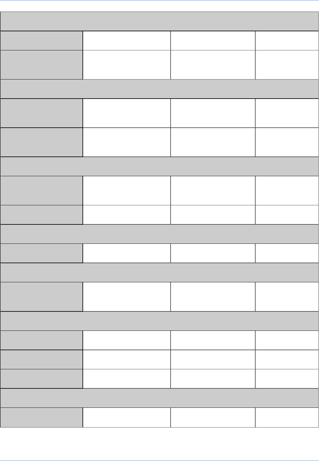
Reference
Remote-Controlling the MOBOTIX Camera
LED Setup
led_events Event LED *
led_arming Arming LED edactiv, ac1, ac2, ac3, ac4,
ac5, acl
edactiv
Arming Delay
inputarm_delay Arming Delay 0, 5, 10, 15, 20, 25, 30, 45,
60, 75, 90
60
inputdisarm_delay Disarming Delay 0, 5, 10, 15, 20, 25, 30, 45,
60, 75, 90
Arming
recording_activ Arm Recording enable, disable, ac1, ac2,
ac3, ac4, ac5, acl, remote
enable
recording_timetable Time Table Profile
Digital Signing
rec_sign Digital Signing 0, 1
Recording Status Symbol
recsymbol Activate Recording Status Sym-
bol
disable, enable disable
Terminate Recording (TR)
freezeactiv Activate Terminate Recording off, on off
freezeevents Termination Condition ~
freezedelay Time Before Terminate 0 .. 86400 15
Full Image Recording
recording_fullimage Activate Full Image Recording 0, 1
446 / 557

Recording (REC)
recording Recording Mode snapshot, streaming_event,
streaming
streaming_event
storypacking Pack Event Story 1, 0
streamframerate100 Continuous Recording Frame
Rate
0, 2500, 1200, 600, 400, 300,
200, 100, 50, 33, 25, 20
100
Start Recording
recstartevents Start Recording *
storyinterval Snap Shot Interval 0 .. 600000 1000
storyantecount Pre-Alarm Images 0, 1, 2, 3, 4, 5, 6, 7, 8, 9, 10,
15, 20, 25, 30, 35, 40, 45, 50
1
storypostcount Post-Alarm Images 0, 1, 2, 3, 4, 5, 6, 7, 8, 9, 10,
15, 20, 25, 30, 35, 40, 45, 50
2
streameventframerate100 Event Frame Rate 0, 2500, 1200, 600, 400, 300,
200, 100, 50, 33, 25, 20
streamantetime Recording Time Before Event 0 .. 15
streamtime Recording Time 2, 4, 6, 8, 10, 20, 30, 40, 50,
60, 70, 80, 90, 120, 180, 300,
420, 600, 900
10
Retrigger Recording
recstretchevents Retrigger Recording ~
Stop Recording
recstopevents Stop Recording ~
storystopcount Images After Stop Event 0, 1, 2, 3, 4, 5, 6, 7, 8, 9, 10,
15, 20, 25, 30, 35, 40, 45, 50
1
streamstoptime Recording Time After Stop
Event
0, 2, 4, 6, 8, 10, 20, 30, 40,
50, 60, 70, 80, 90, 120, 180,
10
Reference
Remote-Controlling the MOBOTIX Camera
447 / 557

Reference
Remote-Controlling the MOBOTIX Camera
300, 420, 600, 900
recstopdeadtime Recording Dead Time 0 .. 3600 5
History Recording (HR)
rechistory_sec History Recording 0, -1, 1
rechistory_cron Recording Time (String constant) * * * * *
rechistory_interval History Recording Interval 10 .. 86400 10
rechistory_imgprof Image Profile for History
recsuspectevents UVV Suspect Trigger ~
recsuspecttimepre Recording Time Before UVV
Suspect
0 .. 120 10
recsuspecttimepost Recording Time After UVV Sus-
pect
0 .. 120 10
Display Options
imageinfo Show Event/Action Symbols 0, 1, 2 1
chartdrawmode Level Meter off, bar, scrollchart off
chartevent Level Meter Data
Object Tracing (OT)
objecttracing Enable Object Tracing disable, enable disable
objectcamera Tracing Camera auto, right, left auto
Genetec audio alarm
audioalarmenabled Genetec audio alarm 1, 0
audioalarmthresh Genetec audio alarm
threshold
0 .. 100 50
448 / 557

Genetec tampering event
tamperingeventenabled Genetec tampering event 1, 0
Parameters for Section 'exposure'↑
Click on the following command to see the unformatted parameters for this section in a new browser win-
dow:
http://172.16.20.86/control/control?list§ion=exposure
Parameter Name in Dialog Possible Values Default Value(s)
Automatic Contrast
automatic Automatic Contrast off, auto, extended, aggressive auto auto
Brightness
brightness Brightness -10, -9, -8, -7, -6, -5, -4, -3, -2, -1,
0, 1, 2, 3, 4, 5, 6, 7, 8, 9, 10
0 0
Backlight Correction
backlight Backlight Correction -10, -9, -8, -7, -6, -5, -4, -3, -2, -1,
0, 1, 2, 3, 4, 5, 6, 7, 8, 9, 10
4 4
Exposure Control
ca_exp_mode Exposure Mode recording, vptz recording recording
ca_exp_window_
type
Exposure Windows extra, all, quarter, center, spot,
top, middle, bottom, right, ver-
tical, left, right_left
quarter quarter
ca_extra_area Custom Windows (Multiline string constant) 0, 224, 168, 832,
624<br>1, 224, 168,
832, 624
ca_exp_window_
weight
Exposure Weighting -1, 0, 10, 20, 30, 40, 50, 60, 70,
80, 90, 100
100 100
ca_wbal_window_ White Balance Weighting -1, 100 -1 -1
Reference
Remote-Controlling the MOBOTIX Camera
449 / 557

Reference
Remote-Controlling the MOBOTIX Camera
weight
ca_exp_window_
draw
Show Windows auto, on, histo auto
Target Brightness
ca_avg_intensity Average Brightness 10, 25, 50, 75, 100, 125, 150,
200, 250, 300, 350, 400, 450,
500, 550, 600, 650, 700, 750,
800
400 400
ca_exp_minavg Minimum Average Brightness 0, 10, 25, 50, 75, 100, 125, 150,
200, 250, 300, 350, 400, 450,
500, 550, 600, 650, 700, 750,
800
200 200
Night Improvement
ca_night_improve Enable Night Improvement off, on on on
Sensor Gain Range
ca_gain_max Sensor Gain Range 6144, 32768, 0 0 0
Exposure Time
ca_exp_corr Exposure Program -2, -1, 0, 1, 2, 4, 6 0 0
ca_exp_max Max. Exposure Time 80, 160, 320, 640, 1280, 2560,
4960, 10080, 20000, 40000,
80000, 160000, 320000, 640000,
1280000
160000 160000
ca_exp_min Min. Exposure Time 80, 160, 320, 640, 1280, 2560,
4960, 10080, 20000, 40000,
80000, 160000, 320000, 640000,
1280000
80 80
Frequency of Power Supply
ca_linefreq Line Frequency 0, 50, 60
450 / 557

Wide Dynamic Range
ca_qwdr_level Wide Dynamic Range 0, 1, 2, 3, 4 0 0
Parameters for Section 'exposurecontrol'↑
Click on the following command to see the unformatted parameters for this section in a new browser win-
dow:
http://172.16.20.86/control/control?list§ion=exposurecontrol
Parameter Name in Dialog Possible Values Default Value(s)
Exposure Control
ca_exp_mode Exposure Mode recording, vptz recording recording
ca_exp_window_
type
Exposure Windows extra, all, quarter, center, spot,
top, middle, bottom, right, ver-
tical, left, right_left
quarter quarter
ca_extra_area Custom Windows (Multiline string constant) 0, 224, 168, 832,
624<br>1, 224, 168,
832, 624
ca_exp_window_
weight
Exposure Weighting -1, 0, 10, 20, 30, 40, 50, 60, 70,
80, 90, 100
100 100
ca_wbal_window_
weight
White Balance Weighting -1, 100 -1 -1
ca_exp_window_
draw
Show Windows auto, on, histo auto
Target Brightness
ca_avg_intensity Average Brightness 10, 25, 50, 75, 100, 125, 150,
200, 250, 300, 350, 400, 450,
500, 550, 600, 650, 700, 750,
800
400 400
ca_exp_minavg Minimum Average Brightness 0, 10, 25, 50, 75, 100, 125, 150,
200, 250, 300, 350, 400, 450,
200 200
Reference
Remote-Controlling the MOBOTIX Camera
451 / 557

Reference
Remote-Controlling the MOBOTIX Camera
500, 550, 600, 650, 700, 750,
800
Night Improvement
ca_night_improve Enable Night Improvement off, on on on
ca_high_gain Permit high gain auto, off, on auto auto
Sensor Gain Range
ca_gain_max Sensor Gain Range 6144, 32768, 0 0 0
Exposure Time
ca_exp_corr Exposure Program -2, -1, 0, 1, 2, 4, 6 0 0
ca_exp_max Max. Exposure Time 80, 160, 320, 640, 1280, 2560,
4960, 10080, 20000, 40000,
80000, 160000, 320000, 640000,
1280000
160000 160000
ca_exp_min Min. Exposure Time 80, 160, 320, 640, 1280, 2560,
4960, 10080, 20000, 40000,
80000, 160000, 320000, 640000,
1280000
80 80
Frequency of Power Supply
ca_linefreq Line Frequency 0, 50, 60
Wide Dynamic Range
ca_qwdr_level Wide Dynamic Range 0, 1, 2, 3, 4 0 0
Parameters for Section 'general'↑
Click on the following command to see the unformatted parameters for this section in a new browser win-
dow:
http://172.16.20.86/control/control?list§ion=general
Parameter Name in Dialog Possible Values Default Value(s)
452 / 557

Camera Selection
camera Camera Selection right, left, auto auto
Camera Night Switch (DY/NI)
nisw_source Switching Source camera, ac1, ac2, ac3, ac4, ac5,
acl
camera
nightswitch Night Camera Level 1, 3, 6, 10, 185, 32, 56, 100, 170,
320, 560, 1000, 1800, 3200
100
nightswitch_irlight IR Light Support disable, enable enable
nightswitchdelay Night Switch Delay 0, 5, 10, 15, 20, 25, 30, 60, 90,
120, 180, 300, 600
5
Image Quality
reduced_mode Image Quality -1, 0, 1 -1
Frame and Data Rate
framerate100 Frames per Second 0, 2500, 2000, 1600, 1400, 1200,
1000, 800, 600, 400
framerate_throttle Playback has Priority disable, prealarm, 2fps 2fps
Mirror & Rotate Image
mirror Mirroring no, vertical, horizontal, both no no
rotate Rotation 0, 90, 180, 270 0 0
adopt_window_
format
Window Orientation 1, 0 1
Sharpness
sharpen Sharpness 0, 1, 2, 3, 4, 5, 6, 7, 8, 9, 10 4 4
sharpen_dark_per-
cent
Automatic Sharpness Control 0, 100 0 0
Reference
Remote-Controlling the MOBOTIX Camera
453 / 557

Reference
Remote-Controlling the MOBOTIX Camera
Noise Filtering
noisesuppress Noise Filtering off, low, high low low
temporal_noise-
suppress
Temporal Noise Filtering off, luma, chroma off off
Obscure Image Area (OA)
obscure_image Obscure Image Area enable, disable, ac1, ac2, ac3,
ac4, ac5, acl
enable
obscure_image_
timetable
Obscure Image Time Table
obscure_image_
area_color
Obscure Image Color 0x000000, 0x800000, 0x008000,
0x808000, 0x000080, 0x800080,
0x008080, 0x808080,
0xC0C0C0, 0xFF0000,
0x00FF00, 0xFFFF00, 0x0000FF,
0xFF00FF, 0x00FFFF, 0xFFFFFF
0x000000
obscure_image_
area
Obscure Image Area (Multiline string constant) 0, 540, 380, 200,
200, 2
Parameters for Section 'imagecontrol'↑
Click on the following command to see the unformatted parameters for this section in a new browser win-
dow:
http://172.16.20.86/control/control?list§ion=imagecontrol
Parameter Name in Dialog Possible Values Default Value(s)
Camera Selection
camera Camera Selection right, left, auto auto
Camera Night Switch (DY/NI)
nisw_source Switching Source camera, ac1, ac2, ac3, ac4,
ac5, acl
camera
454 / 557

nightswitch Night Camera Level 1, 3, 6, 10, 185, 32, 56, 100,
170, 320, 560, 1000, 1800,
3200
100
nightswitch_irlight IR Light Support disable, enable enable
nightswitchdelay Night Switch Delay 0, 5, 10, 15, 20, 25, 30, 60, 90,
120, 180, 300, 600
5
Image Quality
reduced_mode Image Quality -1, 0, 1 -1
IR-Cut Filter
ircutmode Operating Mode auto, irpass, ircut ircut
ircut_level_pass IR-Cut Threshold Pass 0 .. 9999 10 10
ircut_level_cut IR-Cut Threshold Cut 0 .. 9999 12 12
Frame and Data Rate
framerate100 Frames per Second 0, 2500, 2000, 1600, 1400,
1200, 1000, 800, 600, 400
framerate_throttle Playback has Priority disable, prealarm, 2fps 2fps
Mirror & Rotate Image
mirror Mirroring no, vertical, horizontal, both no no
rotate Rotation 0, 90, 180, 270 0 0
adopt_window_
format
Window Orientation 1, 0 1
Sharpness
sharpen Sharpness 0, 1, 2, 3, 4, 5, 6, 7, 8, 9, 10 4 4
sharpen_dark_per-
cent
Automatic Sharpness Control 0, 100 0 0
Reference
Remote-Controlling the MOBOTIX Camera
455 / 557

Reference
Remote-Controlling the MOBOTIX Camera
Focusing Aid
sharpnessadjust Focusing Aid disable, enable, audio disable
Noise Filtering
noisesuppress Noise Filtering off, low, high low low
temporal_noise-
suppress
Temporal Noise Filtering off, luma, chroma off off
Automatic Contrast
automatic Automatic Contrast off, auto, extended, aggress-
ive
auto auto
Brightness
brightness Brightness -10, -9, -8, -7, -6, -5, -4, -3, -2, -
1, 0, 1, 2, 3, 4, 5, 6, 7, 8, 9, 10
0 0
Backlight Correction
backlight Backlight Correction -10, -9, -8, -7, -6, -5, -4, -3, -2, -
1, 0, 1, 2, 3, 4, 5, 6, 7, 8, 9, 10
4 4
White Balance
wb_profile Color Profile -4, -2, -3, 16000, 10000, 8000,
7000, 5500, 5000, 4000,
3000, 2500, -1
-4 -4
Color Saturation
color Color Saturation -10, -9, -8, -7, -6, -5, -4, -3, -2, -
1, 0, 1, 2, 3, 4, 5, 6, 7, 8, 9, 10
0 0
color_dark_percent Automatic Saturation Control 0, 100 0 0
Blue Balance
blue Blue Balance -10, -9, -8, -7, -6, -5, -4, -3, -2, -
1, 0, 1, 2, 3, 4, 5, 6, 7, 8, 9, 10
0 0
456 / 557

Red Balance
red Red Balance -10, -9, -8, -7, -6, -5, -4, -3, -2, -
1, 0, 1, 2, 3, 4, 5, 6, 7, 8, 9, 10
0 0
Video Codec
motionjpeg Video Codec disable, enable enable
mxpeg_transfer1 Transfer Rate I 0 .. 100 15
mxpeg_transfer2 Transfer Rate II 0 .. 100 15
mxpeg_minclass Minimum MCU Change 0 .. 255 128
mxpeg_fulljpeg Switch to Full Image 0 .. 255 255
mxpeg_neighbours Transfer Neighbors disable, enable enable
mxpeg_bewareof-
heavymotion
High Change Rate disable, enable disable
mxpeg_high-
sensitivity
MxPEG High Sensitivity Mode disable, enable disable
JPEG Quality
quality JPEG Quality 10, 20, 30, 40, 50, 60, 70, 80,
90
60
JPEG User Comment
jpegcommentuser JPEG User Comment (String constant)
JPEG Comment Text (CT)
jpegcomment_ctx Comment Text Rows 0 .. 64 1
jpegcomment_ctclear Clear Comment on Match (String constant)
EXIF Data
jpegcomment_exif EXIF Data 1, 0
Reference
Remote-Controlling the MOBOTIX Camera
457 / 557

Reference
Remote-Controlling the MOBOTIX Camera
Text Display
textdisplay Text Display disable, enable, datetime enable
textcolor Text Color 0x000000, 0x800000,
0x008000, 0x808000,
0x000080, 0x800080,
0x008080, 0x808080,
0xC0C0C0, 0xFF0000,
0x00FF00, 0xFFFF00,
0x0000FF, 0xFF00FF,
0x00FFFF, 0xFFFFFF
0xFFFFFF
textbgcolor Background Color 0x000000, 0x800000,
0x008000, 0x808000,
0x000080, 0x800080,
0x008080, 0x808080,
0xC0C0C0, 0xFF0000,
0x00FF00, 0xFFFF00,
0x0000FF, 0xFF00FF,
0x00FFFF, 0xFFFFFF
0x000000
textbgopacity Background Opacity 0, 25, 50, 75, 100
date Date and Time 0, 1, 2, 3, 4, 5, 6 1
print Comment (Multiline string constant) WWW.MOBOTIX.COM
displayfontsize Display Font Size 8, 16, 24 8
fontsize Error Font Size 8, 10, 12, 16, 24, 48 12
errortext Error Messages 0, 1 1
stitchmode Cover Borders off, on on
Obscure Image Area (OA)
obscure_image Obscure Image Area enable, disable, ac1, ac2, ac3,
ac4, ac5, acl
enable
obscure_image_
timetable
Obscure Image Time Table
458 / 557

obscure_image_area_
color
Obscure Image Color 0x000000, 0x800000,
0x008000, 0x808000,
0x000080, 0x800080,
0x008080, 0x808080,
0xC0C0C0, 0xFF0000,
0x00FF00, 0xFFFF00,
0x0000FF, 0xFF00FF,
0x00FFFF, 0xFFFFFF
0x000000
obscure_image_area Obscure Image Area (Multiline string constant) 0, 540, 380, 200,
200, 2
Color Palette
uhu_spec Color Palette 0, 1, 2, 3, 4 2 2
uhu_spec_show Show Color Palette 1, 0 1 1
Thermal Range
uhu_spec_auto Automatic Adjustment enable, disable enable enable
uhu_min Minimum Thermal Value 0 .. 1023 45 45
uhu_max Maximum Thermal Value 0 .. 1023 500 500
uhu_update_direct_
enable
Allow Immediate Updates 1, 0 0 0
uhu_update_speed Update Speed 0, 1, 2 1 1
uhu_temp_spread Level of Detail 0, 1, 2 0 0
Value Range
uhu_gain_mode Value Range 0, 1, 2 0 0
Linear Mode
uhu_tlinear_enable Enable Linear Mode 1, 0 1 1
Thermal Raw Data
uhu_raw_data Export Thermal Raw Data disable, enable, recording disable
Reference
Remote-Controlling the MOBOTIX Camera
459 / 557

Reference
Remote-Controlling the MOBOTIX Camera
Temperature Compensation
uhu_tcomp_configure Manual Configuration 1, 0 0 0
uhu_tcomp_scn_emis Object Emissivity 50 .. 100 100 100
uhu_tcomp_atm_trns Atmospheric Transmission 50 .. 100 100 100
uhu_tcomp_atm_
temp
Ambient Temperature -30 .. 60 22 22
Parameters for Section 'imageprogram'↑
Click on the following command to see the unformatted parameters for this section in a new browser win-
dow:
http://172.16.20.86/control/control?list§ion=imageprogram
Parameter Name in Dialog Possible Values Default Value(s)
Automatic Contrast
automatic Automatic Contrast off, auto, extended, aggressive auto auto
Brightness
brightness Brightness -10, -9, -8, -7, -6, -5, -4, -3, -2, -1,
0, 1, 2, 3, 4, 5, 6, 7, 8, 9, 10
0 0
Backlight Correction
backlight Backlight Correction -10, -9, -8, -7, -6, -5, -4, -3, -2, -1,
0, 1, 2, 3, 4, 5, 6, 7, 8, 9, 10
4 4
Sharpness
sharpen Sharpness 0, 1, 2, 3, 4, 5, 6, 7, 8, 9, 10 4 4
sharpen_dark_per-
cent
Automatic Sharpness Control 0, 100 0 0
Night Improvement
460 / 557

ca_night_improve Enable Night Improvement off, on on on
ca_exp_window_
type
Exposure Windows extra, all, quarter, center, spot,
top, middle, bottom, right, ver-
tical, left, right_left
quarter quarter
ca_exp_window_
weight
Exposure Weighting -1, 0, 10, 20, 30, 40, 50, 60, 70,
80, 90, 100
100 100
ca_wbal_window_
weight
White Balance Weighting -1, 100 -1 -1
Target Brightness
ca_avg_intensity Average Brightness 10, 25, 50, 75, 100, 125, 150,
200, 250, 300, 350, 400, 450,
500, 550, 600, 650, 700, 750,
800
400 400
ca_exp_minavg Minimum Average Brightness 0, 10, 25, 50, 75, 100, 125, 150,
200, 250, 300, 350, 400, 450,
500, 550, 600, 650, 700, 750,
800
200 200
ca_exp_window_
draw
Show Windows auto, on, histo auto
Exposure Time
ca_exp_corr Exposure Program -2, -1, 0, 1, 2, 4, 6 0 0
ca_exp_max Max. Exposure Time 80, 160, 320, 640, 1280, 2560,
4960, 10080, 20000, 40000,
80000, 160000, 320000, 640000,
1280000
160000 160000
ca_exp_min Min. Exposure Time 80, 160, 320, 640, 1280, 2560,
4960, 10080, 20000, 40000,
80000, 160000, 320000, 640000,
1280000
80 80
Sensor Gain Range
Reference
Remote-Controlling the MOBOTIX Camera
461 / 557

Reference
Remote-Controlling the MOBOTIX Camera
ca_gain_max Sensor Gain Range 6144, 32768, 0 0 0
bestquality Best Quality disable, enable disable
Parameters for Section 'jpeg'↑
Click on the following command to see the unformatted parameters for this section in a new browser win-
dow:
http://172.16.20.86/control/control?list§ion=jpeg
Parameter Name in Dialog Possible Values Default Value(s)
Video Codec
motionjpeg Video Codec disable, enable enable
mxpeg_high-
sensitivity
MxPEG High Sensitivity Mode disable, enable disable
JPEG Quality
quality JPEG Quality 10, 20, 30, 40, 50, 60, 70, 80, 90 60
JPEG User Comment
jpegcommentuser JPEG User Comment (String constant)
JPEG Comment Text (CT)
jpegcomment_ctx Comment Text Rows 0 .. 64 1
jpegcomment_
ctclear
Clear Comment on Match (String constant)
EXIF Data
jpegcomment_exif EXIF Data 1, 0
462 / 557

Parameters for Section 'mxpegparam'↑
Click on the following command to see the unformatted parameters for this section in a new browser win-
dow:
http://172.16.20.86/control/control?list§ion=mxpegparam
Parameter Name in Dialog Possible Values Default Value(s)
Camera Selection
camera Camera Selection right, left, auto auto
Frame and Data Rate
framerate100 Frames per Second 0, 2500, 2000, 1600, 1400, 1200,
1000, 800, 600, 400
Brightness
brightness Brightness -10, -9, -8, -7, -6, -5, -4, -3, -2, -1,
0, 1, 2, 3, 4, 5, 6, 7, 8, 9, 10
0 0
Sharpness
sharpen Sharpness 0, 1, 2, 3, 4, 5, 6, 7, 8, 9, 10 4 4
JPEG Quality
quality JPEG Quality 10, 20, 30, 40, 50, 60, 70, 80, 90 60
Video Codec
motionjpeg Video Codec disable, enable enable
mxpeg_transfer1 Transfer Rate I 0 .. 100 15
mxpeg_transfer2 Transfer Rate II 0 .. 100 15
mxpeg_minclass Minimum MCU Change 0 .. 255 128
mxpeg_fulljpeg Switch to Full Image 0 .. 255 255
mxpeg_neighbours Transfer Neighbors disable, enable enable
ca_exp_window_
type
Exposure Windows extra, all, quarter, center, spot,
top, middle, bottom, right, ver-
quarter quarter
Reference
Remote-Controlling the MOBOTIX Camera
463 / 557

Reference
Remote-Controlling the MOBOTIX Camera
tical, left, right_left
ca_exp_window_
draw
Show Windows auto, on, histo auto
Arming
edactiv Arming enable, disable, ac1, ac2, ac3,
ac4, ac5, acl, remote
disable
edacttimetable Time Table Profile
Arming
recording_activ Arm Recording enable, disable, ac1, ac2, ac3,
ac4, ac5, acl, remote
enable
recording_
timetable
Time Table Profile
Recording (REC)
recording Recording Mode snapshot, streaming_event,
streaming
streaming_event
Parameters for Section 'quickcontrol'↑
Click on the following command to see the unformatted parameters for this section in a new browser win-
dow:
http://172.16.20.86/control/control?list§ion=quickcontrol
Parameter Name in Dialog Possible Values Default Value(s)
Camera Selection
camera Camera Selection right, left, auto auto
Image Quality
reduced_mode Image Quality -1, 0, 1 -1
Brightness
464 / 557

brightness Brightness -10, -9, -8, -7, -6, -5, -4, -3, -2, -1,
0, 1, 2, 3, 4, 5, 6, 7, 8, 9, 10
0 0
Backlight Correction
backlight Backlight Correction -10, -9, -8, -7, -6, -5, -4, -3, -2, -1,
0, 1, 2, 3, 4, 5, 6, 7, 8, 9, 10
4 4
Color Saturation
color Color Saturation -10, -9, -8, -7, -6, -5, -4, -3, -2, -1,
0, 1, 2, 3, 4, 5, 6, 7, 8, 9, 10
0 0
Sharpness
sharpen Sharpness 0, 1, 2, 3, 4, 5, 6, 7, 8, 9, 10 4 4
JPEG Quality
quality JPEG Quality 10, 20, 30, 40, 50, 60, 70, 80, 90 60
Focusing Aid
sharpnessadjust Focusing Aid disable, enable, audio disable
Exposure Control
ca_exp_mode Exposure Mode recording, vptz recording recording
ca_exp_window_
type
Exposure Windows extra, all, quarter, center, spot,
top, middle, bottom, right, ver-
tical, left, right_left
quarter quarter
ca_exp_window_
draw
Show Windows auto, on, histo auto
Arming
edactiv Arming enable, disable, ac1, ac2, ac3,
ac4, ac5, acl, remote
disable
Arming
recording_activ Arm Recording enable, disable, ac1, ac2, ac3, enable
Reference
Remote-Controlling the MOBOTIX Camera
465 / 557

Reference
Remote-Controlling the MOBOTIX Camera
ac4, ac5, acl, remote
Display Options
imageinfo Show Event/Action Symbols 0, 1, 2 1
Recording Status Symbol
recsymbol Activate Recording Status Symbol disable, enable disable
vPTZ Actions
view_lock_glob Lock all common display modes none, all none
Mouse Wheel Zoom
zoom_lock_wheel Mouse Wheel Zoom 1, 0 1
Parameters for Section 'quickcontrolreset'↑
Click on the following command to see the unformatted parameters for this section in a new browser win-
dow:
http://172.16.20.86/control/control?list§ion=quickcontrolreset
Parameter Name in Dialog Possible Values Default Value(s)
Camera Selection
camera Camera Selection right, left, auto auto
Camera Night Switch (DY/NI)
nisw_source Switching Source camera, ac1, ac2, ac3, ac4,
ac5, acl
camera
nightswitch Night Camera Level 1, 3, 6, 10, 185, 32, 56, 100,
170, 320, 560, 1000, 1800,
3200
100
nightswitch_irlight IR Light Support disable, enable enable
nightswitchdelay Night Switch Delay 0, 5, 10, 15, 20, 25, 30, 60, 90, 5
466 / 557

120, 180, 300, 600
Image Quality
reduced_mode Image Quality -1, 0, 1 -1
IR-Cut Filter
ircutmode Operating Mode auto, irpass, ircut ircut
ircut_level_pass IR-Cut Threshold Pass 0 .. 9999 10 10
ircut_level_cut IR-Cut Threshold Cut 0 .. 9999 12 12
Frame and Data Rate
framerate100 Frames per Second 0, 2500, 2000, 1600, 1400,
1200, 1000, 800, 600, 400
framerate_throttle Playback has Priority disable, prealarm, 2fps 2fps
Mirror & Rotate Image
mirror Mirroring no, vertical, horizontal, both no no
rotate Rotation 0, 90, 180, 270 0 0
adopt_window_
format
Window Orientation 1, 0 1
Sharpness
sharpen Sharpness 0, 1, 2, 3, 4, 5, 6, 7, 8, 9, 10 4 4
sharpen_dark_per-
cent
Automatic Sharpness Control 0, 100 0 0
Focusing Aid
sharpnessadjust Focusing Aid disable, enable, audio disable
Noise Filtering
noisesuppress Noise Filtering off, low, high low low
Reference
Remote-Controlling the MOBOTIX Camera
467 / 557

Reference
Remote-Controlling the MOBOTIX Camera
temporal_noise-
suppress
Temporal Noise Filtering off, luma, chroma off off
Automatic Contrast
automatic Automatic Contrast off, auto, extended, aggress-
ive
auto auto
Brightness
brightness Brightness -10, -9, -8, -7, -6, -5, -4, -3, -2, -
1, 0, 1, 2, 3, 4, 5, 6, 7, 8, 9, 10
0 0
Backlight Correction
backlight Backlight Correction -10, -9, -8, -7, -6, -5, -4, -3, -2, -
1, 0, 1, 2, 3, 4, 5, 6, 7, 8, 9, 10
4 4
White Balance
wb_profile Color Profile -4, -2, -3, 16000, 10000, 8000,
7000, 5500, 5000, 4000,
3000, 2500, -1
-4 -4
Color Saturation
color Color Saturation -10, -9, -8, -7, -6, -5, -4, -3, -2, -
1, 0, 1, 2, 3, 4, 5, 6, 7, 8, 9, 10
0 0
color_dark_percent Automatic Saturation Control 0, 100 0 0
Blue Balance
blue Blue Balance -10, -9, -8, -7, -6, -5, -4, -3, -2, -
1, 0, 1, 2, 3, 4, 5, 6, 7, 8, 9, 10
0 0
Red Balance
red Red Balance -10, -9, -8, -7, -6, -5, -4, -3, -2, -
1, 0, 1, 2, 3, 4, 5, 6, 7, 8, 9, 10
0 0
Video Codec
468 / 557

motionjpeg Video Codec disable, enable enable
mxpeg_transfer1 Transfer Rate I 0 .. 100 15
mxpeg_transfer2 Transfer Rate II 0 .. 100 15
mxpeg_minclass Minimum MCU Change 0 .. 255 128
mxpeg_fulljpeg Switch to Full Image 0 .. 255 255
mxpeg_neighbours Transfer Neighbors disable, enable enable
mxpeg_bewareof-
heavymotion
High Change Rate disable, enable disable
mxpeg_high-
sensitivity
MxPEG High Sensitivity Mode disable, enable disable
JPEG Quality
quality JPEG Quality 10, 20, 30, 40, 50, 60, 70, 80,
90
60
JPEG User Comment
jpegcommentuser JPEG User Comment (String constant)
JPEG Comment Text (CT)
jpegcomment_ctx Comment Text Rows 0 .. 64 1
jpegcomment_ctclear Clear Comment on Match (String constant)
EXIF Data
jpegcomment_exif EXIF Data 1, 0
Text Display
textdisplay Text Display disable, enable, datetime enable
textcolor Text Color 0x000000, 0x800000,
0x008000, 0x808000,
0x000080, 0x800080,
0xFFFFFF
Reference
Remote-Controlling the MOBOTIX Camera
469 / 557

Reference
Remote-Controlling the MOBOTIX Camera
0x008080, 0x808080,
0xC0C0C0, 0xFF0000,
0x00FF00, 0xFFFF00,
0x0000FF, 0xFF00FF,
0x00FFFF, 0xFFFFFF
textbgcolor Background Color 0x000000, 0x800000,
0x008000, 0x808000,
0x000080, 0x800080,
0x008080, 0x808080,
0xC0C0C0, 0xFF0000,
0x00FF00, 0xFFFF00,
0x0000FF, 0xFF00FF,
0x00FFFF, 0xFFFFFF
0x000000
textbgopacity Background Opacity 0, 25, 50, 75, 100
date Date and Time 0, 1, 2, 3, 4, 5, 6 1
print Comment (Multiline string constant) WWW.MOBOTIX.COM
displayfontsize Display Font Size 8, 16, 24 8
fontsize Error Font Size 8, 10, 12, 16, 24, 48 12
errortext Error Messages 0, 1 1
stitchmode Cover Borders off, on on
Obscure Image Area (OA)
obscure_image Obscure Image Area enable, disable, ac1, ac2, ac3,
ac4, ac5, acl
enable
obscure_image_
timetable
Obscure Image Time Table
obscure_image_area_
color
Obscure Image Color 0x000000, 0x800000,
0x008000, 0x808000,
0x000080, 0x800080,
0x008080, 0x808080,
0xC0C0C0, 0xFF0000,
0x00FF00, 0xFFFF00,
0x000000
470 / 557

0x0000FF, 0xFF00FF,
0x00FFFF, 0xFFFFFF
obscure_image_area Obscure Image Area (Multiline string constant) 0, 540, 380, 200,
200, 2
Color Palette
uhu_spec Color Palette 0, 1, 2, 3, 4 2 2
uhu_spec_show Show Color Palette 1, 0 1 1
Thermal Range
uhu_spec_auto Automatic Adjustment enable, disable enable enable
uhu_min Minimum Thermal Value 0 .. 1023 45 45
uhu_max Maximum Thermal Value 0 .. 1023 500 500
uhu_update_direct_
enable
Allow Immediate Updates 1, 0 0 0
uhu_update_speed Update Speed 0, 1, 2 1 1
uhu_temp_spread Level of Detail 0, 1, 2 0 0
Value Range
uhu_gain_mode Value Range 0, 1, 2 0 0
Linear Mode
uhu_tlinear_enable Enable Linear Mode 1, 0 1 1
Thermal Raw Data
uhu_raw_data Export Thermal Raw Data disable, enable, recording disable
Temperature Compensation
uhu_tcomp_configure Manual Configuration 1, 0 0 0
uhu_tcomp_scn_emis Object Emissivity 50 .. 100 100 100
Reference
Remote-Controlling the MOBOTIX Camera
471 / 557

Reference
Remote-Controlling the MOBOTIX Camera
uhu_tcomp_atm_trns Atmospheric Transmission 50 .. 100 100 100
uhu_tcomp_atm_
temp
Ambient Temperature -30 .. 60 22 22
Exposure Control
ca_exp_mode Exposure Mode recording, vptz recording recording
ca_exp_window_type Exposure Windows extra, all, quarter, center,
spot, top, middle, bottom,
right, vertical, left, right_left
quarter quarter
ca_extra_area Custom Windows (Multiline string constant) 0, 224, 168, 832,
624<br>1, 224, 168,
832, 624
ca_exp_window_
weight
Exposure Weighting -1, 0, 10, 20, 30, 40, 50, 60,
70, 80, 90, 100
100 100
ca_wbal_window_
weight
White Balance Weighting -1, 100 -1 -1
ca_exp_window_draw Show Windows auto, on, histo auto
Target Brightness
ca_avg_intensity Average Brightness 10, 25, 50, 75, 100, 125, 150,
200, 250, 300, 350, 400, 450,
500, 550, 600, 650, 700, 750,
800
400 400
ca_exp_minavg Minimum Average Brightness 0, 10, 25, 50, 75, 100, 125,
150, 200, 250, 300, 350, 400,
450, 500, 550, 600, 650, 700,
750, 800
200 200
Night Improvement
ca_night_improve Enable Night Improvement off, on on on
ca_high_gain Permit high gain auto, off, on auto auto
472 / 557

Sensor Gain Range
ca_gain_max Sensor Gain Range 6144, 32768, 0 0 0
Exposure Time
ca_exp_corr Exposure Program -2, -1, 0, 1, 2, 4, 6 0 0
ca_exp_max Max. Exposure Time 80, 160, 320, 640, 1280,
2560, 4960, 10080, 20000,
40000, 80000, 160000,
320000, 640000, 1280000
160000 160000
ca_exp_min Min. Exposure Time 80, 160, 320, 640, 1280,
2560, 4960, 10080, 20000,
40000, 80000, 160000,
320000, 640000, 1280000
80 80
Frequency of Power Supply
ca_linefreq Line Frequency 0, 50, 60
Wide Dynamic Range
ca_qwdr_level Wide Dynamic Range 0, 1, 2, 3, 4 0 0
Display Options
imageinfo Show Event/Action Symbols 0, 1, 2 1
chartdrawmode Level Meter off, bar, scrollchart off
chartevent Level Meter Data
Object Tracing (OT)
objecttracing Enable Object Tracing disable, enable disable
objectcamera Tracing Camera auto, right, left auto
vPTZ Actions
view_lock_glob Lock all common display modes none, all none
Reference
Remote-Controlling the MOBOTIX Camera
473 / 557

Reference
Remote-Controlling the MOBOTIX Camera
Mouse Wheel Zoom
zoom_lock_wheel Mouse Wheel Zoom 1, 0 1
Zoom Quality
zoom_thresh Zoom Quality 0, 1600, 2000, 3200, 4000 2000
Auto Move
automove_pause Pause Time 0 .. 120 10
automove_tour_1 Auto Move Tour 1 (String constant) 1, 2, 3
automove_tour_2 Auto Move Tour 2 (String constant) 1, 2, 3
automove_tour_3 Auto Move Tour 3 (String constant) 1, 2, 3
PTZ Control
activate_pano_osc On-Screen PTZ Control 0, 1
Parameters for Section 'recording'↑
Click on the following command to see the unformatted parameters for this section in a new browser win-
dow:
http://172.16.20.86/control/control?list§ion=recording
Parameter Name in Dialog Possible Values Default Value(s)
Arming
recording_activ Arm Recording enable, disable, ac1, ac2,
ac3, ac4, ac5, acl, remote
enable
recording_timetable Time Table Profile
Digital Signing
rec_sign Digital Signing 0, 1
Recording Status Symbol
474 / 557

recsymbol Activate Recording Status Sym-
bol
disable, enable disable
Terminate Recording (TR)
freezeactiv Activate Terminate Recording off, on off
freezeevents Termination Condition ~
freezedelay Time Before Terminate 0 .. 86400 15
Recording (REC)
recording Recording Mode snapshot, streaming_event,
streaming
streaming_event
storypacking Pack Event Story 1, 0
streamframerate100 Continuous Recording Frame
Rate
0, 2500, 1200, 600, 400, 300,
200, 100, 50, 33, 25, 20
100
Start Recording
recstartevents Start Recording *
storyinterval Snap Shot Interval 0 .. 600000 1000
storyantecount Pre-Alarm Images 0, 1, 2, 3, 4, 5, 6, 7, 8, 9, 10,
15, 20, 25, 30, 35, 40, 45, 50
1
storypostcount Post-Alarm Images 0, 1, 2, 3, 4, 5, 6, 7, 8, 9, 10,
15, 20, 25, 30, 35, 40, 45, 50
2
streameventframerate100 Event Frame Rate 0, 2500, 1200, 600, 400, 300,
200, 100, 50, 33, 25, 20
streamantetime Recording Time Before Event 0 .. 15
streamtime Recording Time 2, 4, 6, 8, 10, 20, 30, 40, 50,
60, 70, 80, 90, 120, 180, 300,
420, 600, 900
10
Retrigger Recording
Reference
Remote-Controlling the MOBOTIX Camera
475 / 557

Reference
Remote-Controlling the MOBOTIX Camera
recstretchevents Retrigger Recording ~
Stop Recording
recstopevents Stop Recording ~
storystopcount Images After Stop Event 0, 1, 2, 3, 4, 5, 6, 7, 8, 9, 10,
15, 20, 25, 30, 35, 40, 45, 50
1
streamstoptime Recording Time After Stop
Event
0, 2, 4, 6, 8, 10, 20, 30, 40,
50, 60, 70, 80, 90, 120, 180,
300, 420, 600, 900
10
recstopdeadtime Recording Dead Time 0 .. 3600 5
History Recording (HR)
rechistory_sec History Recording 0, -1, 1
rechistory_cron Recording Time (String constant) * * * * *
rechistory_interval History Recording Interval 10 .. 86400 10
rechistory_imgprof Image Profile for History
Full Image Recording
recording_fullimage Activate Full Image Recording 0, 1
Camera Selection
camera Camera Selection right, left, auto, live live
JPEG Quality
quality JPEG Quality 10, 20, 30, 40, 50, 60, 70, 80,
90
60
Text Display
textdisplay Text Display disable, enable, datetime datetime
date Date and Time 0, 1, 2, 3, 4, 5, 6 1
476 / 557

print Comment (Multiline string constant)
displayfontsize Display Font Size 8, 16, 24 16
Parameters for Section 'settings'↑
Click on the following command to see the unformatted parameters for this section in a new browser win-
dow:
http://172.16.20.86/control/control?list§ion=settings
Parameter Name in Dialog Possible Values Default Value(s)
Arming
edactiv Arming enable, disable, ac1, ac2, ac3,
ac4, ac5, acl, remote
disable
edacttimetable Time Table Profile
Custom Signal 1 (CS1)
armcond_ac1_
source
Source disable, enable, signal_input,
time_table, remote, action, illu
disable
armcond_ac1_sig-
nalin_which
Signal Input ob%2C1, DI%2C~BPC,
DI%2C~DPC
ob, 1
armcond_ac1_sig-
nalin_state
Signal Input State si_open, si_close si_open
armcond_ac1_
timetable
Time Table
armcond_ac1_illu_
level
Trigger Level (String constant) 100.0
armcond_ac1_illu_
src
Illumination Source right, left, both, auto auto
armcond_ac1_illu_
cmp
Comparison higher, lower higher
Reference
Remote-Controlling the MOBOTIX Camera
477 / 557

Reference
Remote-Controlling the MOBOTIX Camera
armcond_ac1_illu_
delay
Delay 0 .. 300 10
Custom Signal 2 (CS2)
armcond_ac2_
source
Source disable, enable, signal_input,
time_table, remote, action, illu
disable
armcond_ac2_sig-
nalin_which
Signal Input ob%2C1, DI%2C~BPC,
DI%2C~DPC
ob, 1
armcond_ac2_sig-
nalin_state
Signal Input State si_open, si_close si_open
armcond_ac2_
timetable
Time Table
armcond_ac2_illu_
level
Trigger Level (String constant) 100.0
armcond_ac2_illu_
src
Illumination Source right, left, both, auto auto
armcond_ac2_illu_
cmp
Comparison higher, lower higher
armcond_ac2_illu_
delay
Delay 0 .. 300 10
Custom Signal 3 (CS3)
armcond_ac3_
source
Source disable, enable, signal_input,
time_table, remote, action, illu
disable
armcond_ac3_sig-
nalin_which
Signal Input ob%2C1, DI%2C~BPC,
DI%2C~DPC
ob, 1
armcond_ac3_sig-
nalin_state
Signal Input State si_open, si_close si_open
armcond_ac3_
timetable
Time Table
armcond_ac3_illu_ Trigger Level (String constant) 100.0
478 / 557

level
armcond_ac3_illu_
src
Illumination Source right, left, both, auto auto
armcond_ac3_illu_
cmp
Comparison higher, lower higher
armcond_ac3_illu_
delay
Delay 0 .. 300 10
Custom Signal 4 (CS4)
armcond_ac4_
source
Source disable, enable, signal_input,
time_table, remote, action, illu
disable
armcond_ac4_sig-
nalin_which
Signal Input ob%2C1, DI%2C~BPC,
DI%2C~DPC
ob, 1
armcond_ac4_sig-
nalin_state
Signal Input State si_open, si_close si_open
armcond_ac4_
timetable
Time Table
armcond_ac4_illu_
level
Trigger Level (String constant) 100.0
armcond_ac4_illu_
src
Illumination Source right, left, both, auto auto
armcond_ac4_illu_
cmp
Comparison higher, lower higher
armcond_ac4_illu_
delay
Delay 0 .. 300 10
Custom Signal 5 (CS5)
armcond_ac5_
source
Source disable, enable, signal_input,
time_table, remote, action, illu
disable
armcond_ac5_sig-
nalin_which
Signal Input ob%2C1, DI%2C~BPC,
DI%2C~DPC
ob, 1
Reference
Remote-Controlling the MOBOTIX Camera
479 / 557

Reference
Remote-Controlling the MOBOTIX Camera
armcond_ac5_sig-
nalin_state
Signal Input State si_open, si_close si_open
armcond_ac5_
timetable
Time Table
armcond_ac5_illu_
level
Trigger Level (String constant) 100.0
armcond_ac5_illu_
src
Illumination Source right, left, both, auto auto
armcond_ac5_illu_
cmp
Comparison higher, lower higher
armcond_ac5_illu_
delay
Delay 0 .. 300 10
Logically Combined Signal (CSL)
armcond_acl_
source
Source disable, ac1_and_ac2, ac1_or_
ac2, remote
disable
Master/Slave
enable_dis-
tributed_camera_
state
Enable Master/Slave 1, 0
master_cam Master Camera (String constant)
replication_pro-
tocol_port
Replication Protocol Port 0 .. 65535 60000
LED Setup
led_events Event LED *
led_arming Arming LED edactiv, ac1, ac2, ac3, ac4, ac5,
acl
edactiv
Arming Delay
inputarm_delay Arming Delay 0, 5, 10, 15, 20, 25, 30, 45, 60, 60
480 / 557

75, 90
inputdisarm_delay Disarming Delay 0, 5, 10, 15, 20, 25, 30, 45, 60,
75, 90
Parameters for Section 'text'↑
Click on the following command to see the unformatted parameters for this section in a new browser win-
dow:
http://172.16.20.86/control/control?list§ion=text
Parameter Name in Dialog Possible Values Default Value(s)
Text Display
textdisplay Text Display disable, enable, datetime enable
textcolor Text Color 0x000000, 0x800000, 0x008000,
0x808000, 0x000080, 0x800080,
0x008080, 0x808080,
0xC0C0C0, 0xFF0000,
0x00FF00, 0xFFFF00, 0x0000FF,
0xFF00FF, 0x00FFFF, 0xFFFFFF
0xFFFFFF
textbgcolor Background Color 0x000000, 0x800000, 0x008000,
0x808000, 0x000080, 0x800080,
0x008080, 0x808080,
0xC0C0C0, 0xFF0000,
0x00FF00, 0xFFFF00, 0x0000FF,
0xFF00FF, 0x00FFFF, 0xFFFFFF
0x000000
textbgopacity Background Opacity 0, 25, 50, 75, 100
date Date and Time 0, 1, 2, 3, 4, 5, 6 1
print Comment (Multiline string constant) WWW.MOBOTIX.COM
displayfontsize Display Font Size 8, 16, 24 8
errortext Error Messages 0, 1 1
fontsize Error Font Size 8, 10, 12, 16, 24, 48 12
Reference
Remote-Controlling the MOBOTIX Camera
481 / 557

Reference
Remote-Controlling the MOBOTIX Camera
stitchmode Cover Borders off, on on
Display Options
imageinfo Show Event/Action Symbols 0, 1, 2 1
chartdrawmode Level Meter off, bar, scrollchart off
chartevent Level Meter Data
Object Tracing (OT)
objecttracing Enable Object Tracing disable, enable disable
objectcamera Tracing Camera auto, right, left auto
Parameters for Section 'thermal'↑
Click on the following command to see the unformatted parameters for this section in a new browser win-
dow:
http://172.16.20.86/control/control?list§ion=thermal
Parameter Name in Dialog Possible Values Default Value(s)
Thermal Raw Data
uhu_raw_data Export Thermal Raw Data disable, enable, recording disable
Color Palette
uhu_spec Color Palette 0, 1, 2, 3, 4 2 2
uhu_spec_show Show Color Palette 1, 0 1 1
Linear Mode
uhu_tlinear_
enable
Enable Linear Mode 1, 0 1 1
Temperature Compensation
uhu_tcomp_con- Manual Configuration 1, 0 0 0
482 / 557

figure
uhu_tcomp_scn_
emis
Object Emissivity 50 .. 100 100 100
uhu_tcomp_atm_
trns
Atmospheric Transmission 50 .. 100 100 100
uhu_tcomp_atm_
temp
Ambient Temperature -30 .. 60 22 22
Value Range
uhu_gain_mode Value Range 0, 1, 2 0 0
Thermal Range
uhu_spec_auto Automatic Adjustment enable, disable enable enable
uhu_min Minimum Thermal Value 0 .. 1023 45 45
uhu_max Maximum Thermal Value 0 .. 1023 500 500
uhu_update_dir-
ect_enable
Allow Immediate Updates 1, 0 0 0
uhu_update_
speed
Update Speed 0, 1, 2 1 1
uhu_temp_spread Level of Detail 0, 1, 2 0 0
Temperature Control Area
ca_exp_mode Temperature Control Mode recording, vptz recording recording
ca_exp_window_
type
Temperature Control Windows extra, all, quarter, center, spot,
top, middle, bottom, right, ver-
tical, left, right_left
quarter quarter
ca_extra_area Custom Windows (Multiline string constant) 0, 224, 168, 832,
624<br>1, 224, 168,
832, 624
ca_exp_window_ Show Windows auto, on, histo auto
Reference
Remote-Controlling the MOBOTIX Camera
483 / 557

Reference
Remote-Controlling the MOBOTIX Camera
draw
Parameters for Section 'videomotionanalysis'↑
Click on the following command to see the unformatted parameters for this section in a new browser win-
dow:
http://172.16.20.86/control/control?list§ion=videomotionanalysis
Parameter Name in Dialog Possible Values Default Value(s)
Parameters for Section 'vptzcontrol'↑
Click on the following command to see the unformatted parameters for this section in a new browser win-
dow:
http://172.16.20.86/control/control?list§ion=vptzcontrol
Parameter Name in Dialog Possible Values Default Value(s)
vPTZ Actions
view_lock_glob Lock all common display modes none, all none
Mouse Wheel Zoom
zoom_lock_wheel Mouse Wheel Zoom 1, 0 1
Zoom Quality
zoom_thresh Zoom Quality 0, 1600, 2000, 3200, 4000 2000
PTZ Control
activate_pano_osc On-Screen PTZ Control 0, 1
Auto Move
automove_pause Pause Time 0 .. 120 10
automove_tour_1 Auto Move Tour 1 (String constant) 1, 2, 3
484 / 557

automove_tour_2 Auto Move Tour 2 (String constant) 1, 2, 3
automove_tour_3 Auto Move Tour 3 (String constant) 1, 2, 3
Parameter Overview of the rcontrol Command
Example: rcontrol?action=sound&soundfile=Alarm
Example: rcontrol?action=message&name=camera_alarm
action= Explanation Parameters
defreeze Unfreezes the camera after Terminate Recording (TR) occurred and
resumes recording.
delete_ref-
erence_image
Delete current reference image.
Only available as administrator under /admin/rcontrol.
delete_sys-
tem_mes-
sages
Delete and reset all system messages.
Only available as administrator under /admin/rcontrol.
emailcurrent Sends the current image by e-mail using the e-mail profile specified by id or
name.
profile
profile id
name
custom
profile
name
emaillastevent Sends the last event image by e-mail using the e-mail profile specified by id
or name.
profile
profile id
name
custom
profile
name
errorack Acknowledges an error notification.
Only available as administrator under /admin/rcontrol.
eventack Acknowledges an event.
exportstatistic Triggers an export of the statistic data generated by MxAnalytics.
Reference
Remote-Controlling the MOBOTIX Camera
485 / 557

Reference
Remote-Controlling the MOBOTIX Camera
format_device Format flash device with MxFFS volumes for Recording and/or MxAnalytics.
Only available as administrator under /admin/rcontrol.
media_type
target
encryption
security_pass-
word
secure_format
num_volumes
mxanalytics_
volume_size_gb
store
reboot
event_recorder_
size_gb
ftpcurrent Sends the current image to the FTP server using the FTP profile specified by
id or name.
profile
profile id
name
custom
profile
name
ftplastevent Sends the last event image to the FTP server using the FTP profile specified
by id or name.
profile
profile id
name
custom
profile
name
generate_ref-
erence_image
Save current image as reference image.
Only available as administrator under /admin/rcontrol.
getrs232 Prints text received from the RS232 interface. nrofbytes
get the
last nrof-
bytes
Bytes
rs232delafterread
0 or 1:
delete
Buffer
after read
getrs232hex Prints text received from the RS232 interface in hex notation. nrofbytes
get the
486 / 557

last nrof-
bytes
Bytes
rs232delafterread
0 or 1:
delete
Buffer
after read
gettemp Gets the camera's internal temperature.
gettext Replace variables in message and print it as plain text. message
text with
variables
irledsoff Switches all infrared LEDs off.
irledson Switches all infrared LEDs on. The optional time parameter switches the
LEDs off after the specified number of seconds.
time
duration
[s]
irledsstring Switches the infrared LEDs specified in the leds parameter. If no string is
specified, the IR LEDs will be switched to default. The optional time para-
meter switches the IR LEDs off after the specified number of seconds.
time
duration
[s]
leds
string, six
chars long,
0=off,
1=on,
b=blink,
d=default,
-= no
change
1st char is
top LED,
rest clock-
wise
ledsdefault Switches LEDs to default.
ledsoff Switches all LEDs off. The optional time parameter switches the LEDs back
to default after the specified number of seconds.
time
duration
[s]
Reference
Remote-Controlling the MOBOTIX Camera
487 / 557

Reference
Remote-Controlling the MOBOTIX Camera
ledson Switches all LEDs on. The optional time parameter switches the LEDs back
to default after the specified number of seconds.
time
duration
[s]
ledsstring Switches LEDs specified in the leds parameter. If no string is specified, the
LEDs will be switched to default. The optional time parameter switches the
LEDs back to default after the specified number of seconds.
time
duration
[s]
leds
string, six
chars long,
0=off,
1=on,
b=blink,
d=default,
-= no
change
1st char is
top LED,
rest clock-
wise
list_plex_
recording_tar-
gets
Lists the event recording targets provided by supported expansion devices.
Set the output parameter to media_types to retrieve the list of supported
media types instead.
Only available as administrator under /admin/rcontrol.
output
mailboxdb_
delete
Will delete an entry from the mailbox db, only. It will not erase the actual
recording on the event storage. Specify the message using its sequence and
event number.
Only available as administrator under /admin/rcontrol.
sequence
a
sequence
number
event
an event
number
mailboxdb_
reset
Delete all entries in the mailbox database!
Only available as administrator under /admin/rcontrol.
mailboxdb_
set_seen_flag
Allows to change the "seen flag", whether a message has been reviewed,
for the message given by its sequence and event number. This has to be fol-
lowed by the flag value. Zero (0) is for unseen messages. Other values for
seen messages.
sequence
a
sequence
number
event
an event
number
488 / 557

seen_flag
mailboxdb
seen flag
(0 unseen)
message Sends the message specified in the name parameter using the MxMes-
sageSystem. The message is distributed within the current LAN (=range
global).
name
custom
profile
name
mxffs_
archive_delete
Delete MxFFS archive files on the file server, and reset current transfers
and statistics! Attention: You will immediately loose all archived recordings!
Only available as administrator under /admin/rcontrol.
mxffs_
archive_
delete_
without_reset
Delete MxFFS archive files on the file server only. No reset of the statistics
queue! Attention: You will immediately loose all archived recordings!
Only available as administrator under /admin/rcontrol.
mxffs_
archive_reset_
tq
Reset all queued MxFFS archive transfers.
Only available as administrator under /admin/rcontrol.
mxffs_
archive_reset_
stats
Reset MxFFS archive statistics.
Only available as administrator under /admin/rcontrol.
mxffs_
archive_resync
Synchronizes the camera's internal MxFFS block recordings with the archive
content by transferring missing blocks (asynchronuous transfer).
Only available as administrator under /admin/rcontrol.
notifycurrent Sends a network message (IP Notify) with the status of the current image. profile
profile id
name
custom
profile
name
notifylastevent Sends a network message (IP Notify) with the status of the last event
image.
profile
profile id
name
custom
profile
name
Reference
Remote-Controlling the MOBOTIX Camera
489 / 557

Reference
Remote-Controlling the MOBOTIX Camera
pancenter Sets the pan position to the center of the current view.
prepare_
format
Prepare format of storage targets. DISABLES RECORDING on selected tar-
get or all USB, SD and CF devices and reboots the camera, if required for
formatting.
Only available as administrator under /admin/rcontrol.
target
putrs232 Sends text specified in the rs232outtext parameter to the RS232 interface. rs232outtext
text to
write to
rs232
reboot Reboots the camera.
Only available as administrator under /admin/rcontrol.
recording_tar-
gets_info
Shows information about available recording targets. When used with check
option, tests for newly connected hardware.
Only available as administrator under /admin/rcontrol.
check
resetconfig Resets the configuration to factory defaults.
Only available as administrator under /admin/rcontrol.
resetstatistic Resets statistic data generated by MxAnalytics.
restoreconfig Restores the current configuration from flash.
Only available as administrator under /admin/rcontrol.
rs232sigin Prints status of the signalin pin of the serial interface.
scanzeroconf Scans for cameras with Zero Configuration Networking enabled. Scan time
is set through parameter time. Default scan time is five seconds.
Only available as administrator under /admin/rcontrol.
time
duration
[s]
sendmessage Sends a network message (IP Notify) specified in the message parameter
to the IP address specified in the addr parameter.
message
text with
variables
addr
host:port
push Send a push notification specified in the message parameter using a push
profile.
profile
profile id
message
text with
variables
490 / 557

set_plex_
recording_tar-
get
Reconfigures event recording to use a specified target on an expansion
device. Either specify the target directly via the target parameter, or indir-
ectly by requesting a specific media_type such as cf, sd or usb. Then store
to flash and reboot in order to activate changes.
Only available as administrator under /admin/rcontrol.
target
media_type
security_pass-
word
set_plex_
recording_tar-
get_and_
reboot
Same as set_plex_recording_target. Also stores the new configuration into
flash and reboots the camera.
Only available as administrator under /admin/rcontrol.
target
media_type
security_pass-
word
settime Sets the current system time. Specify the time in seconds since the epoch.
If in NTP client mode, triggers a resync to the time server; the time para-
meter is optional in this case.
Only available as administrator under /admin/rcontrol.
time
duration
[s]
sigout Triggers the signal out profile as specified using the profile parameter. profile
profile id
name
custom
profile
name
sound Play back a given sound profile or sound file. If both are given, the former
takes precendece over the latter.
profile
profile id
name
custom
profile
name
soundfile
name of
sound file
speakip Outputs the camera's current IP address on the speaker.
storeconfig Stores the current configuration to flash.
Only available as administrator under /admin/rcontrol.
test_fileserver Runs a file server test. time
duration
[s]
userclick Triggers a User Click (UC) event.
Reference
Remote-Controlling the MOBOTIX Camera
491 / 557

Reference
Remote-Controlling the MOBOTIX Camera
voipcall Triggers VoIP call-out using the sip address specified in the sipaddr para-
meter.
sipaddr
sipaddress
voiphangup Hangs up VoIP call-out.
voipphone Triggers VoIP call-out using the profile specified by id or name. profile
profile id
name
custom
profile
name
voiprestart Restarts the VoIP software of the camera.
Please note that the following actions have become obsolete and are deprecated. They are still supported for
legacy purposes.
"setrs232sig", "sigouthigh", "sigoutlow", "MxMessageSystem"
The Remote Configuration API
The remote configuration API (Application Programming Interface) http://<IP address>/ad-
min/remoteconfig provides the methods used for remotely changing configuration parameters directly
on the camera.
Using the Remote Configuration API
The camera's HTTP interface processes commands and configuration parameters in an HTTP POST request as
in the following example:
POST /admin/remoteconfig HTTP/1.0
Content-type: application/x-www-form-urlencoded
Authorization: Basic YWRtaW46bWVpbnNt
Content-length: 87
helo
view section audio
write params
audio/MICRO=1
view section audio
update
store
quit
Explanation of the HTTP POST Request in the Example
492 / 557

Part
POST /admin/remoteconfig HTTP/1.0
Content-type: application/x-www-form-urlencoded
Authorization: Basic YWRtaW46bWVpbnNt
Content-length: 87
Description
Header of the HTTP POST Request.
Part
Description
Empty line; separates the request's header from its content.
Part
helo
Description
Beginning of the command sequence.
Part
view section audio
write params
audio/MICRO=1
view section audio
update
store
Description
Command sequence with specific commands, as described in the Commands of the Remote Con-
figuration API section.
Part
quit
Description
End of the command sequence.
Remarks
n
Make sure to close the command sequence with a blank and a line break at the end.
Reference
Remote-Controlling the MOBOTIX Camera
493 / 557

Reference
Remote-Controlling the MOBOTIX Camera
n
The content type (Content-type: application/x-www-form-urlen-
coded) does not need to be specified, but it is expected by the camera's web
server.
n
The web server handles authentication (in this case, Basic authentication is used).
User name and password are concatenated by a colon (":") and Base64-encoded.
See the line above for the "admin:meinsm" user name and password.
n
The length of the content (Content-length) is the length of the entire data that
follows the blank line after the header.
n
The content of the request itself is processed line by line.
n
Note that you need to URL-encode special characters in the parameters, as
described in the Command Conventions section of the The HTTP API help page.
This example is discussed in detail in Output of the Remote Configuration API using the cURL command line
application.
Commands of the Remote Configuration API
You can use the commands as shown in the following syntax samples:
n
Simple command:
<command>
n
Command with keyword, separated by spaces:
<command> <keyword>
n
Command with parameters, separated by spaces:
<command> <parameter1> <parameter2>
n
Command keyword and one or more parameters, separated by spaces:
<command> <keyword> <parameter1> <parameter2>
Available Commands
Command
reset
Description
Resets the entire camera configuration or individual sections thereof to the factory default values.
Keyword
Result
configfile
Resets the entire configuration.
section
Only resets the sections of the configuration that are specified as parameters.
exceptsection
Resets all sections of the configuration except the ones specified as parameters.
494 / 557

Command
restore
Description
Restores the configuration from the copy in Flash storage.
Keyword
Result
configfile
Restores the entire configuration.
section
Only restores the sections of the configuration that are specified as parameters.
Command
delete
Description
Deletes the entire configuration, specific sections or individual parameters.
Keyword
Result
configfile
Deletes the entire configuration.
section
Only deletes the sections of the configuration that are specified as parameters.
params
Only deletes the parameters of the configuration that are specified in the following lines. The
parameters for deletion are specified by the section name followed by "/" as separator:
<section name>/<parameter>
When dealing with profiles, the profile name is expanding the section name, again separated by
a "/".
<section name>/<profile name>/<parameter>
In order to access a profile such as
SECTION ipnotify
profile=ip0:<value>
ENDSECTION ipnotify
use the following string
Reference
Remote-Controlling the MOBOTIX Camera
495 / 557

Reference
Remote-Controlling the MOBOTIX Camera
ipnotify/ip0/profile
Command
write
Description
Writes entire sections or –when used with the params keyword in front– individual parameters of
the configuration.
Keyword
Result
(not specified)
Writes the sections of the configuration that are specified in the following lines. Note that the
sections need to be specified with start and end lines:
SECTION <section name1>
<parameter>=<value>
<parameter>=<value>
ENDSECTION <section name1>
SECTION <section name2>
<parameter>=<value>
ENDSECTION <section name2>
params
Writes the parameters of the configuration that are specified in the following lines. The para-
meters are specified by the section name followed by "/" as separator:
<section name>/<parameter>=<value>
When dealing with profiles, the profile name is expanding the section name, again separated by
a "/".
<section name>/<profile name>/<parameter>=<value>
In order to access a profile such as
SECTION ipnotify
profile=ip0:<value>
ENDSECTION ipnotify
use the following string
496 / 557

ipnotify/ip0/profile
Note
Profiles can only be written as a whole. Accessing individual parameters of a
profile is not possible.
Command
append
Description
Appends data to configuration sections. The parameters to append to a section are specified line by
line between SECTION and ENDSECTION as in the following:
SECTION <section name>
Parameter=<value>
Parameter=<value>
ENDSECTION <section name>
Command
view
Description
Returns (shows) the entire configuration or specific sections.
Keyword
Result
configfile
Returns the entire configuration.
section
Only returns the sections of the configuration that are specified as parameters.
Command
store
Description
Permanently stores the configuration in the camera's Flash memory.
Command
reboot
Description
Reboots the camera.
Command
update
Reference
Remote-Controlling the MOBOTIX Camera
497 / 557

Reference
Remote-Controlling the MOBOTIX Camera
Description
Applies all changes to the configuration that can be activated without rebooting the camera.
Keyword
Result
all (or without keyword)
Activates all changes.
section
Only applies the changes to the sections that are specified as parameters.
Command
profile
Description
Returns one line with the name of the current configuration profile. This line is empty, if no profile is
active.
Command
activate_profile
Description
Activates the configuration profile specified as parameter: activate_profile <profile name>
Command
reboot_needed
Description
Returns all changed configuration sections, which require a reboot before they can be applied. This
line is empty, if no change requires a reboot.
Note
After changing the entire configuration (using write, reset, delete or after
uploading/editing the configuration from the web interface), the camera does not
know if certain configuration sections have been changed. In this case, the com-
mand returns the answer "unknown".
Command
exit quit
Description
Identical meaning. Both commands end the preceding command and close the API command
sequence. Note that you can only use one of these two commands in a command sequence.
Command
help
Description
Returns a list of available commands (see Returning a List of Commands Using help).
Output of the Remote Configuration API
498 / 557

The camera API returns its answers line by line:
n
The results consist of the data returned by the executed command.
n
Informational output starts with "#" and documents the progress while processing the commands.
n
Error messages start with "ERROR:", followed by a description of the error that occurred.
n
Commands without results data (reset, store, etc.) do not have any output.
n
If no errors have occurred, the camera acknowledges this by returning "OK" before closing.
Example: Activating the Microphone
This example demonstrates how to activate the microphone using an HTTP request. For easily testing the
remote configuration API, the cURL command line tool (http://curl.haxx.se/download.html) can be down-
loaded for Windows. It is automatically installed on Mac OSX and most Linux computers.
Using cURL allows quickly and easily testing the commands, since this tool handles the communication
with the camera. For example, cURL automatically sends the correct header and calculates the length of the
command sequence.
Commands
helo
view section audio
write params
audio/MICRO=1
view section audio
update
store
quit
Description
# Beginning of the command sequence.
# Output the audio section.
# Write the parameter specified in the following line.
# Set the MICRO parameter in the audio section to the value "1".
# Output audio section once more.
# Apply the changes without rebooting.
# Store the configuration in the camera's flash memory.
# End of the command sequence.
Step-by-step instruction:
Reference
Remote-Controlling the MOBOTIX Camera
499 / 557

Reference
Remote-Controlling the MOBOTIX Camera
n
Open a command shell (Windows) or a terminal (Mac OSX, Linux).
n
Enter the following command line and replace <user name>, <password> and <IP address>
by the actual data of your camera:
curl -q -v -u "<user name>:<password>" --data-binary @- "http://<IP
address>/admin/remoteconfig"
n
Press the [Return] key; cURL is now waiting for commands.
n
Copy the text block from the left column of the last table from helo to quit.
n
Copy the contents of the clipboard to the command shell or terminal.
n
Press the [Ctrl+D] key combination twice (Windows, Linux) or once (Mac OSX) to send the command
sequence to the camera.
Output of the command sequence with the following data:
n
<user name>: admin
n
<password>: meinsm
n
<IP address>: 10.8.0.118
* About to connect() to 10.8.0.118 port 80 (#0)
* Trying 10.8.0.118... connected
* Connected to 10.8.0.118 port 80 (#0)
* Server auth using Basic with user 'admin'
> POST /admin/remoteconfig HTTP/1.1
> Authorization: Basic YWRtaW46bWVpbnNt
> User-Agent: curl/7.18.2 (i486-pc-linux-gnu) libcurl/7.18.2
OpenSSL/0.9.8g zlib/1.2.3.3 libidn/1.8 libssh2/0.18
> Host: 10.8.0.118
> Accept: */*
> Content-Length: 87
> Content-Type: application/x-www-form-urlencoded
>* HTTP 1.0, assume close after body
< HTTP/1.0 200 OK
< Content-Type: text/plain; charset=utf-8
< Cache-Control: no-cache
<#read:helo:
#read:view section audio:
#exec cmd=view section audio
SECTION audio
SPEAKER=1
MICRO=0
PREAMPLIFIER=2
500 / 557

SPEAKERLEVEL=0
ENDSECTION audio
#read:write params:
#exec cmd=write params
#read:view section audio:
#exec cmd=view section audio
SECTION audio
SPEAKER=1
MICRO=1
PREAMPLIFIER=2
SPEAKERLEVEL=0
ENDSECTION audio
#read:update:
#exec cmd=update
#updating daemons!
#read:store:
#exec cmd=store
#Storing to flash...
#read:quit:
OK
#bye
* Closing connection #0
Note
Output beginning with a "*", "<" or ">" character is generated by cURL. In the output,
">" precedes the commands sent to the camera, while "<" precedes the messages
returned by the camera's web server. The remaining lines are returned by the remote con-
figuration API, as described in the Output of the Remote Configuration API section.
Example: Returning a List of Commands Using help
Commands
helo
help
quit
Description
Reference
Remote-Controlling the MOBOTIX Camera
501 / 557

Reference
Remote-Controlling the MOBOTIX Camera
# Beginning of the command sequence.
# Call the help of the Remote Configuration API
# End of the command sequence.
Step-by-step instruction:
n
Open a command shell (Windows) or a terminal (Mac OSX, Linux).
n
Enter the following command line and replace <user name>, <password> and <IP address>
by the actual data of your camera:
curl -q -v -u "<user name>:<password>" --data-binary @- "http://<IP
address>/admin/remoteconfig"
n
Press the [Return] key; cURL is now waiting for commands.
n
Copy the text block from the left column of the last table from helo to quit.
n
Copy the contents of the clipboard to the command shell or terminal.
n
Press the [Ctrl+D] key combination twice to send the command sequence to the camera.
Output of the command sequence with the following data:
n
<user name>: admin
n
<password>: meinsm
n
<IP address>: 10.8.0.118
* About to connect() to 10.8.0.118 port 80 (#0)
* Trying 10.8.0.118... connected
* Connected to 10.8.0.118 port 80 (#0)
* Server auth using Basic with user 'admin'
> POST /admin/remoteconfig HTTP/1.1
> Authorization: Basic YWRtaW46bWVpbnNt
> User-Agent: curl/7.18.2 (i486-pc-linux-gnu) libcurl/7.18.2
OpenSSL/0.9.8g zlib/1.2.3.3 libidn/1.8 libssh2/0.18
> Host: 10.8.0.118
> Accept: */*
> Content-Length: 87
> Content-Type: application/x-www-form-urlencoded
>* HTTP 1.0, assume close after body
< HTTP/1.0 200 OK
< Content-Type: text/plain; charset=utf-8
< Cache-Control: no-cache
<#read:helo:
502 / 557

#read:help:
The following commands are currently implemented:
append
reboot_needed
view
reboot
write
profile
restore
activate_profile
reset
update
delete
store
exit
quit
help
#read:quit:
OK
#bye
* Closing connection #0
Note
Output beginning with a "*", "<" or ">" character is generated by cURL. In the output,
">" precedes the commands sent to the camera, while "<" precedes the messages
returned by the camera's web server. The remaining lines are returned by the remote con-
figuration API, as described in the Output of the Remote Configuration API section.
Example: Changing a Profile Line Using write
The ipnotifyaddress target address of the network message profile ip0 in the ipnotify con-
figuration section is to be changed from 10.0.0.42:8000 to 10.11.12.13:6750.
Note
Make sure that you always need to write the entire profile line. It is not possible to change
individual values within a profile.
Commands
Reference
Remote-Controlling the MOBOTIX Camera
503 / 557

Reference
Remote-Controlling the MOBOTIX Camera
helo
view section ipnotify
write params
ipnotify/ip0/profile=ip0:_profilename=MxCC-Alarm
:preset=mxpeg_alarm:ackn_time=60
:ipnotifyaddress=10.11.12.13%3A6750
:send=on_error:protocol=raw
:boundary=--next-image--:httppath=:httpauth=
:data=msg:ipnotifymessage=Hello World!
:filetype=mxg:rate100=100:antetime=1
:posttime=1:systime=1440:ipnotifyport=0
view section ipnotify
update
store
quit
Description
# Beginning of the command sequence.
# Output the ipnotify section.
# Write the profile specified in the following line.
# Set profile ip0 in section ipnotify with the address
# "10.11.12.13" and the port 6750 ...
# ...
# ...
# ...
# ...
# ...
# ...
# Again output the ipnotify section.
# Apply the changes without rebooting.
# Store the configuration in the camera's flash memory.
# End of the command sequence.
Step-by-step instruction:
504 / 557

n
Open a command shell (Windows) or a terminal (Mac OSX, Linux).
n
Enter the following command line and replace <user name>, <password> and <IP address>
by the actual data of your camera:
curl -q -v -u "<user name>:<password>" --data-binary @- "http://<IP
address>/admin/remoteconfig"
n
Press the [Return] key; cURL is now waiting for commands.
n
Copy the text block from the left column of the last table from helo to quit.
n
Copy the contents of the clipboard to the command shell or terminal.
n
Press the [Ctrl+D] key combination twice to send the command sequence to the camera.
Output of the command sequence with the following
data:
n
<user name>: admin
n
<password>: meinsm
n
<IP address>: 10.8.0.118
* About to connect() to 10.8.0.118 port 80 (#0)
* Trying 10.8.0.118... connected
* Connected to 10.8.0.118 port 80 (#0)
* Server auth using Basic with user 'admin'
> POST /admin/remoteconfig HTTP/1.1
> Authorization: Basic YWRtaW46bWVpbnNt
> User-Agent: curl/7.18.2 (i486-pc-linux-gnu) libcurl/7.18.2
OpenSSL/0.9.8g zlib/1.2.3.3 libidn/1.8 libssh2/0.18
> Host: 10.8.0.118
> Accept: */*
> Content-Length: 87
> Content-Type: application/x-www-form-urlencoded
>* HTTP 1.0, assume close after body
< HTTP/1.0 200 OK
< Content-Type: text/plain; charset=utf-8
< Cache-Control: no-cache
<#read:helo:
#read:view section ipnotify:
#exec cmd=view section ipnotify
SECTION ipnotify
ipnotify/ip0/profile=ip0:_profilename=MxCC-Alarm
:preset=mxpeg_alarm:ackn_time=60
Reference
Remote-Controlling the MOBOTIX Camera
505 / 557

Reference
Remote-Controlling the MOBOTIX Camera
:ipnotifyaddress=10.0.0.42%3A8000
:send=on_error:protocol=raw
:boundary=--next-image--:httppath=:httpauth=
:data=msg:ipnotifymessage=Hello World!
:filetype=mxg:rate100=100:antetime=1
:posttime=1:systime=1440:ipnotifyport=0
...
ENDSECTION ipnotify
#read:write params:
#exec cmd=write params
#read:view section ipnotify:
#exec cmd=view section ipnotify
SECTION ipnotify
ipnotify/ip0/profile=ip0:_profilename=MxCC-Alarm
:preset=mxpeg_alarm:ackn_time=60
:ipnotifyaddress= 10.11.12.13%3A6750
:send=on_error:protocol=raw
:boundary=--next-image--:httppath=:httpauth=
:data=msg:ipnotifymessage=Hello World!
:filetype=mxg:rate100=100:antetime=1
:posttime=1:systime=1440:ipnotifyport=0
...
ENDSECTION ipnotify
#read:update:
#exec cmd=update
#updating daemons!
#read:store:
#exec cmd=store
#Storing to flash...
#read:quit:
OK
#bye
506 / 557

* Closing connection 0
Note
Output beginning with a "*", "<" or ">" character is generated by cURL. In the output,
">" precedes the commands sent to the camera, while "<" precedes the messages
returned by the camera's web server. The remaining lines are returned by the remote con-
figuration API, as described in the Output of the Remote Configuration API section.
CGI Parameters of the MOBOTIX Camera
To retrieve images of the camera directly from the integrated web server, you can use one of the following
HTTP commands:
n
http://<IP address>/record/current.jpg
Retrieves a camera image according to the current image settings. You cannot specify any additional
parameters. This HTTP API supports so-called HTTP Keep Alive connections to optimize the retrieval of
several images per second. Note that the best image rates are obtained using the faststream.jpg
API (see Parameters for faststream.jpg).
n
http://<IP address>/cgi-bin/image.jpg
Retrieves a camera image using additional image parameters. For example, the following command
will display an image from the right camera lens, size 320x240 mm with an image quality of 60%:
http://<IP address>/cgi-bin/image.jpg?cam-
era=right&size=320x240&quality=60
The saved configuration is not changed.
Appending ?help to the end of the command will display the corresponding help page:
http://<IP address>/cgi-bin/image.jpg?help
See Parameters for image.jpg for additional information.
n
http://<IP address>/cgi-bin/faststream.jpg (guest access)
http://<IP address>/control/faststream.jpg (user access)
Retrieves the live stream from the camera using additional image parameters. For example, the fol-
lowing command will show the live stream as M-JPEG from the camera in a generated HTML page:
http://<IP address>/cgi-bin/faststream.jpg?stream=full&html
Appending ?help to the end of the command will display the corresponding help page:
http://<IP address>/cgi-bin/faststream.jpg?help
For additional information on the parameters for guest and user access, see Parameters for fast-
stream.jpg.
n
http://<IP address>/control/event.jpg
Provides access the camera's events and allows adding additional parameters. The following request,
for example, delivers the last event image of the camera:
http://<IP address>/control/event.jpg?sequence=head
Appending ?help to the end of the command will display the corresponding help page:
http://<IP address>/control/event.jpg?help
See Parameters for event.jpg for additional information.
Reference
Remote-Controlling the MOBOTIX Camera
507 / 557

Reference
Remote-Controlling the MOBOTIX Camera
Note
If MxPEG has been activated in the camera, the frame rate will be reduced for ten
seconds if an image is pulled from the camera using one of the image profiles.
Parameters for image.jpg
Note
Please note that the contents of this frame will only be displayed if the API right in the
Group Access Control Lists is publicly accessible or the group of your user name has this
right.
Parameter Overview of the image.jpg Command, p. 509
Note
Except for the help and current parameters, you can combine any number of para-
meters in any order.
Parameters for faststream.jpg
Guest
Access:
The URL http://<IP address>/cgi-bin/faststream.jpg provides guest access to the live
stream. For additional information on how to set the maximum and preset image refresh rate, see the Start
Page help page.
User
Access:
The URL http://<IP address>/control/faststream.jpg provides user access to the live stream.
For additional information on how to set the maximum and preset image refresh rate, see the Start Page
help page. This access has been optimized for high image rates and thus delivers a video stream in MxPEG
format, which has to be decoded accordingly.
Please download the MOBOTIX SDK from www.mobotix.com in the Support> Developer Tools section for
detailed instructions.
Note
Please note that the contents of this frame will only be displayed if the API right in the
Group Access Control Lists is publicly accessible or the group of your user name has this
right.
Parameter Overview of the faststream.jpg Command, p. 512
Parameters for event.jpg
Note
508 / 557

Please note that the contents of this frame will only be displayed if the API right in the
Group Access Control Lists is publicly accessible or the group of your user name has this
right.
Parameter Overview of the event.jpg Command, p. 514
Parameter Overview of the image.jpg Command
Example: image.jpg?size=1024x768&sharpen=5&quality=90
Parameter=Default Values Explanation
help Help
This overview.
current Current Live Image
Generate image from /record/current.jpg.
All other parameters are ignored.
config Current Configuration
Generate image with parameters from current configuration file.
Other parameters can overwrite them.
fip=10.x.x.x Escaped
string
Factory IP
Will only deliver an image if the camera has this factory IP address.
error=picture picture
empty
content
current
Error Handling
Sets the error handling options in case no image is available:
picture: returns the "No frame available!" image
empty: returns nothing
content: returns only the content type
current: returns the current.jpg image
imgprof= Escaped
string
Image Profile
Load parameters from this image profile. At first, the current configuration
is read and will be overwritten by the settings of the image profile.
preview Preview Mode
Output image in the format given by the parameter size. It may be smaller
to keep the aspect ratio.
view=0 -1..256 View
Loads the specified view if given. Omitted or set to 0 falls back to the cur-
rent (or factory default) live view.
Reference
Remote-Controlling the MOBOTIX Camera
509 / 557

Reference
Remote-Controlling the MOBOTIX Camera
Image Parameter
camera=live right
left
both
live
thermal
Camera Selection
Image sensor used for JPEG conversion.
Note: A Day&Night camera always shows the appropriate image sensor
depending on the current illumination.
display_mod-
e=lenscorr_l11
simple
lenscorr_
l11
lenscorr_
l22
surround
panorama
pano_dbl
pano_
focus
pip
piz
Display Mode
pipposition=bot_right bot_right
bot_left
top_right
top_left
Position of the inset image
Select the image corner in which the inset image is displayed.
double_pip=off off
on
Enlarge inset image
Display the inset image with twice the width and height.
size=1024x768 Escaped
string
Image Size
Enter the desired image size. If you select an aspect ratio other than 4:3, the
image will show a centered section of the full sensor.
customsize=800x400 Escaped
string
Custom Image Size
Enter the desired image size. If you select an aspect ratio other than 4:3, the
image will show a centered section of the full sensor. This parameter over-
writes the size parameter.
sharpen=4 0..10 Sharpness
quality=60 10..90 JPEG Quality
textdisplay=enable disable Text Display
510 / 557

enable
datetime
Enable or disable text display:
datetime displays date & time only.
textcolor=0xFFFFFF Escaped
string
Text Color
Enter hexadecimal color value: 0xRRGGBB
textbgopacity=0 0..100 Text Background Opacity
Opacity of the background color in percent.
textbgcolor=0x000000 Escaped
string
Text Background Color
Enter hexadecimal color value: 0xRRGGBB
stitchmode=on off
on
Cover Borders
Covers the borders of inset or dual images with bars.
displayfontsize=8 8..24 Display Font Size
Font size for text display. Supported values are 8, 16 and 24.
date=0 0..7 Insert Date & Time
0 = off
1 = Date, time zone, time
2 = Time
3 = Time, milliseconds
4 = Date
5 = Long date
6 = Date, time & milliseconds
7 = Time zone
print= Escaped
string
Text Display
The text follows CGI syntax rules:
'%0A' for return, '+' for space and so on.
mirror=no no
vertical
horizontal
both
Mirror
rotate=0 0..360 Rotation
Currently only 0° and 180° available.
noisesuppress=low off
low
high
Noise Suppression
Select level of noise suppression.
Reference
Remote-Controlling the MOBOTIX Camera
511 / 557

Reference
Remote-Controlling the MOBOTIX Camera
temporal_noise-
suppress=off
off
luma
chroma
Temporal Noise Suppression
Method of temporal noise reduction.
showlogo= Logo Profile
Logo profile to display in the image.
Repeat this parameter to display several logos.
Parameter Overview of the faststream.jpg Command
Example: faststream.jpg?stream=full&fps=1.0
Parameter=Default Values Explanation
help Help
This overview.
stream=MxPEG full
MxPEG
mxg
Stream Type
Image data in stream:
full: full JPEG images
MxPEG: MOBOTIX optimized JPEG
mxg: MxPEG Clipfile; not server push
noaudio No Audio Switch
Disable audio data in image stream.
Audio is only available for MxPEG streams.
needlength Need Content-Length
Send HTTP content-length for every frame in server push stream.
Note: This option is not useful for browsers.
fps=16 Escaped
string
Frames per Second
Frame rate of streamed images:
e.g. '3.0' streaming with 3 frames per second. Set to 0 for maximum frame rate.
iframerefresh=0 0..60 Seconds between new I-frames
I-frame interval in seconds.
0: turn off
Note: Using this option disables jpheaderrefresh and jpheaderupdate.
jpheaderupdate=0 0..1000 Frames between tables refreshs
Table refresh count. 0: off, 1: every frame, 2: every second frame, ...
512 / 557

jpheaderrefresh=10 0..60 Seconds between table refreshs
Table refresh time. 0: off, 1: every second, 2: every second second, ...
framecount=0 0.. Frame Counter
Amount of images delivered before stream stops (0=infinite).
fip=10.x.x.x Escaped
string
Factory IP
Will only deliver an image if the camera has this factory IP address.
error=picture picture
empty
content
current
Error Handling
Sets the error handling options in case no image is available:
picture: returns the "No frame available!" image
empty: returns nothing
content: returns only the content type
current: returns the current.jpg image
html HTML Page With Stream
Output HTML demo page including stream.
preview Preview Mode
Output image in the format given by the parameter size. It may be smaller to
keep the aspect ratio.
size= Escaped
string
Image Size
Enter the desired image size in format [width]x[height].
Only used if the parameter preview is specified.
quality=60 10..90 JPEG Quality
Enter the desired JPEG quality.
Only used if the parameter preview is specified.
camera=both right
left
both
Preview Camera
Select the part of a double image that is displayed.
Only used if the parameters preview or roi are specified and if the live
stream of the camera shows both sensors.
roi Region of Interest
Output a part of the image given by the parameters roisize or camera.
roisize= Escaped
string
RoI Rectangle
Enter an RoI rectangle in MCU format (blocks of 16x16 pixels), e.g. 2x3x12x10
(offsetX, offsetY, width, height).
Only used if the parameter roi is specified.
Reference
Remote-Controlling the MOBOTIX Camera
513 / 557

Reference
Remote-Controlling the MOBOTIX Camera
Parameter Overview of the event.jpg Command
Example: event.jpg?sequence=head&offset=-1
Parameter=Default Values Explanation
help Help
This overview.
sequence=head Escaped string Sequence Number
Accepted values are
0..999999: Number of Sequence
head: last sequence
tail: oldest sequence
offset=0 -
999999..999999
Sequence Offset
Offset to the sequence number.
eno=-1 -1..99999 Alarm Image Offset
Offset to the alarm image number.
Accepted values are
-1: last alarm image found in sequence
0 = E00000.jpg
1 = E00001.jpg
2 = E00002.jpg
...
alarmimage= Escaped string Alarm Image Address
Address for an alarm image. This parameter combines sequence and
eno separated by a dot.
length=5 1..10000 Alarm List Length
Number of alarms in the output alarmlist.
timespan=3600 1.. Alarm List Time Span
Time span in seconds from Time Search Starting Time searchbytime_
start to the last alarm displayed in the output alarmlist. Can be
combined with parameter length.
filter=* Escaped string Alarm Filter List
Optional event filter for output alarmlist and alarmupdate.
Example: VM,UC,PE,TT
514 / 557

story=0 -99999..99999 Story Offset
View an image or clip file out of the story:
-3 = A00001.jpg
-2 = A00002.jpg
-1 = A00003.jpg
0 = E00000.jpg
1 = P00001.jpg, M00001.jpg or C00001.jpg
2 = P00002.jpg or M00002.jpg
3 = P00003.jpg or M00003.jpg
...
direct=0 -99999..99999 Direct Story Offset
Directly load the story image or clip file without retrieving a story size:
-1 = A00001.jpg
-2 = A00002.jpg
-3 = A00003.jpg
0 = E00000.jpg
Same procedure as Story Offset on post alarm files.
source=auto auto
intern
extern
Image Storage Source
Select the image storage:
auto: prefer external, but use intern on fail
intern: use the internal event buffer
extern: use the external storage
volume= Escaped string Volume ID
Use this option to access alarms and information from volumes in bank-
ing mode.
Examples:
0: accessing live buffer / last alarm buffer 10.x.x.x (no extension)
1: accessing alarm buffer 10.x.x.x
S: accessing suspect buffer 10.x.x.x.S
Note: do not combine with option source.
fip=10.x.x.x Escaped string Factory IP
Will only deliver an image if the camera has this factory IP address.
error=picture picture
empty
content
current
Error Handling
Sets the error handling options in case no image is available:
picture: returns the "No frame available!" image
empty: returns nothing
content: returns only the content type
current: returns the current.jpg image
Reference
Remote-Controlling the MOBOTIX Camera
515 / 557

Reference
Remote-Controlling the MOBOTIX Camera
output=jpeg jpeg
jpeg_download
m1img
evtinfo
evtinfo_d
mxg
m1imgtab
alarmlist
alarmupdate
certificate
sequencecheck
alarmlist_exten-
ded
Output Format
Output format of event JPEG:
jpeg: Save as JPEG.
jpeg_download: Opens browser download dialog for saving the JPEG.
m1img: Print only the JPEG comment.
m1imgtab: Print JPEG comment with variable parser, using format string
tableformat (example).
evtinfo: Print event information, e.g. recording mode, story count and
event number.
evtinfo_d: Print normal and detailed event information, e.g. story size,
frame number and time stamp.
mxg: Entire event story in one clip file.
alarmlist: Print a list of alarm images using JSON format (using this JSON
Schema).
alarmlist_extended: Print an alarmlist with more detailed information.
alarmupdate: Print a row of alarm information for each new alarm.
certificate: Output the certificate used for signing the event images.
sequencecheck: Detect manipulations of the camera time and lost or cor-
rupted sequences.
include_mailbox_
changes
Mailbox Information
Mailbox start alarms in output format alarmupdate list additional
information.
verify Verify Signature
Verify recorded sequences. Only available for output formats event
information (output=evtinfo[_d]) and sequencecheck.
preview Preview Mode
Output image in the format given by the parameter size. It may be
smaller to keep the aspect ratio.
size= Escaped string Image Size
Enter the desired image size in format [width]x[height].
Only used if the parameter preview is specified.
quality=60 10..90 JPEG Quality
Enter the desired JPEG quality.
Only used if the parameter preview is specified.
camera=both right
left
both
Preview Camera
Select the part of a double image that is displayed.
Only used if the parameter preview is specified.
516 / 557

searchbytime_
start=
Escaped string Time Search Starting Time
Request an image via its timestamp [seconds.microseconds] since the
Epoch (00:00:00 UTC, January 1, 1970).
Additional Information
This section provides additional information for working with the MOBOTIX camera.
The MxWeb Interface
MxWeb is the new user interface for the web browser. This page allows seeing the live images and also
provides access to the recordings. To reduce bandwidth requirements, MxWeb uses MxPEG as video format.
In addition, MxWeb uses standard technologies that are supported by most of the current web browsers.
Browsers need to support these technologies: HTML5, WebGL and Web Audio. It is also advisable to use a
browser that supports the asm.js JavaScript extension.
The current releases of the following browsers are supported: Google Chrome, Apple Safari, Mozilla Firefox
and Microsoft Edge.
Note
MxWeb is still in the beta stage. This means that you will not have access to all camera fea-
tures on this page. The standard website is totally independent and can be used parallel to
the new interface.
Starting MxWeb
n
To start MxWeb directly, open http://<IP address>:8080 for unencrypted and https://<IP
address>:8081 for encrypted connections.
n
If you want to use the automatic redirect to MxWeb, simply click on this link.
To configure MxWeb, open the Webserver dialog. Note that you can also use MxWeb as the start page of the
camera in the Language and Start Page dialog.
MxManagementCenter, MxControlCenter, and MxEasy
If you enable the MxPEG parameter in the JPEG Settings dialog, the camera creates a combined audio/video
stream using MOBOTIX video encoding. MxPEG allows for large-format live video and audio streaming (audio
only if supported by the camera model) at extremely low network load (1% at 100Mbps).
For viewing and storing the stream, you need MxManagementCenter, MxControlCenter, MxEasy or the
MxPEG ActiveX plugin for Internet Explorer. While MxManagementCenter and MxControlCenter can be
used for creating complex video surveillance systems, MxEasy is better suited for small to medium-size sys-
tems (max. 16 cameras). MxEasy also puts special emphasis on intuitive and comfortable handling of the sur-
veillance system. Starting with version 1.3, MxEasy is also capable of managing and automatically
configuring the MOBOTIX IP Video Door Station.
MxManagementCenter, MxControlCenter and MxEasy are available at the MOBOTIX website free of charge
in the Support > Software Downloads section. This section also contains the latest version of the MxPEG
ActiveX Plug-in for Internet Explorer.
Reference
Additional Information
517 / 557

Reference
Additional Information
The programs/program components also provide bidirectional voice connections via the network (Voice over
IP or VoIP), provided that adequate bandwidth is available.
For more information on MxManagementCenter, MxControlCenter and MxEasy, please open the
Support> Manuals section on www.mobotix.com.
The Privacy Mode
Use the Privacy Mode, if you would like to deactivate the whole system, i.e. recording and any kind of cam-
era access is rendered impossible until you deactivate this mode. While this lock can be deactivated directly
from this computer, you will need the user name and password set in this dialog to deactivate the lock from
a different computer. Note that the cameras are also signaling this operating mode by a specific LED blinking
pattern.
Activating the "Privacy Mode"
To activate this mode, enter a user name and password, then click on the Set button.
Caution
This mode becomes effective immediately after you click on the Set button. If you would
like to access the camera again, you need to use the access data you defined when activ-
ating the Privacy Mode.
Effects Of The "Privacy Mode"
n
The camera only accepts the access data (user name and password) you defined in the Privacy Mode
dialog. Without these access data, you cannot deactivate the Privacy Mode any more.
n
The camera's entire image generation process is deactivated.
n
Recording is deactivated completely.
n
The camera's audio channel is switched off.
n
The camera shows a distinctive blinking pattern so you can see that the cameras are in this mode (see
below).
Signaling by the Camera LEDs
The different MOBOTIX cameras are displaying the following blinking patterns once they have been switched
to Privacy Mode:
Camera Type LEDs Blinking Pattern
Cameras with four LEDs LED0 flashes red every 3 seconds
LED3 flashes red every 3 seconds, in sync with LED0
518 / 557

Camera Type LEDs Blinking Pattern
Cameras with two LEDs LED0 flashes green every 3 seconds
LED1 flashes green every 3 seconds, in sync with LED0
Deactivating the Privacy Mode
Proceed as follows to deactivate the Privacy Mode:
n
Start a browser, enter the IP address of the camera and enter the access data you defined before.
n
Open the Privacy Mode dialog (http://<camera IP address>/admin/privacymode).
n
Click on the Set button to deactivate the Privacy Mode.
Description of Parameters
Parameter Description
User Name The user name for accessing the camera if the Privacy Mode is active.
Password The password for accessing the camera if the Privacy Mode is active.
Graphically Entering Image Areas
Some of the camera features, such as Video Motion Detection (VM), Obscure Image Area (OA), Exposure
Windows, Custom Size and Free Zoom / Crop options use windows within the image sensors that you can
define and modify for the corresponding image sensor or the visible image section using graphical means.
Defining New Windows
1.
Open the camera's Live image.
2.
Hold down the [Shift] key and left-click inside the displayed image with your mouse. This spot is high-
lighted in yellow.
3.
Release the [Shift] key and click on a second spot of the image area. The selected image area is now dis-
played as a yellow frame in the live image.
Hold down the [Ctrl] key during this step to define a rectangle that has the same proportions as the cur-
rent image format (default is 4:3).
4.
Then click on the button in the dialog to add the rectangle coordinates to the corresponding definition
text field.
Notes
n
The yellow frame in the live image disappears after the coordinates have been
entered in a definition box by clicking on one of the buttons or the zoom feature, or
after 60 seconds at the latest. After first the [Shift]-click, the camera will wait 10
seconds for you to follow up with a second click.
Reference
Additional Information
519 / 557

Reference
Additional Information
n
If images or video sequences are stored while the yellow marker or the yellow frame
are displayed (i.e. due to events or by a time task), the yellow elements will also be
stored.
n
If you select a rectangle for Custom Size while displaying two images side-by-side
(Camera Selection Quick Control: Both), the same area will be used on both image
sensors, i.e. the visible image will be twice as wide as the selection.
n
The camera always clips the rectangle at the border between the images when the
camera shows both image sensors. Selecting one area from both sensors is not pos-
sible.
See also
The Live Screen of the MOBOTIX Camera
Definition of Counting Corridors in MxAnalytics
Note that the MxAnalytics functions include the definition of counting corridors. Proceed as follows to draw
a counting corridor in the live image instead of a rectangle.
1.
Open the camera's Live image.
2.
Hold down the [Ctrl+Shift] keys and left-click inside the displayed image with your mouse. This spot is
highlighted in yellow.
3.
In order to define the direction and length of the counting corridor, hold down the [Shift] key and click
again into the live image.
4.
Click again to set the width of the counting corridor.
5.
Then click on the button in the dialog to add the counting corridor coordinates to the corresponding
definition field.
Using Variables
Variables can be used in various dialogs and are replaced at runtime by the actual values:
n
File or directory name in the FTP Profiles dialog.
n
Subject or body text in the Email Profiles dialog
n
Network messages in the Messaging dialog
n
Comments in the Text & Display Settings dialog
Notes
n
Apart from the variables listed above, you can also use Placeholders for Dynamic
Image Text.
n
When retrieving data from one of the supported weather stations connected to the
serial interface, weather variables will allow displaying the weather data in the
image.
n
Note that variables are not case-sensitive.
n
Information on formatting variables is contained in the Formatting Options section
in this help page.
520 / 557

n
Optional parts of variables are written in angular brackets and do not have to be
used.
n
Note that a maximum of 25 variables can be used at the same time.
Variable Description
The variable's syntax is as follows:
$(GROUP.VARIABLE[,formatting options[,..]])
Variable Description Note
LEV / LASTEVENT: Last Event
$(LEV.DATE)
Date and time of the
last event
YYYY-MM-DD hh:mm:ss
$(LEV.TIME)
Time of the last
event
hh:mm:ss
$(LEV.SECONDS)
Seconds since the
last event
Seconds
$(LEV.RELATIV)
Time since the last
event
hh:mm:ss
EVT / EVENT: Event
$(EVT.AST), $(EVENT.AST)
Displays all activated
Action Groups.
See also
Abbre-
viations
Used in
the
MOBOTIX
Camera
$(EVT.EST.SELECTED),
$(EVENT.EST.SELECTED)
Displays all active
events.
See also
Abbre-
viations
Used in
the
MOBOTIX
Camera
$(EVT.EST.ACTIVATED),
$(EVENT.EST.ACTIVATED)
Displays the event
that triggered an
alarm.
See also
Abbre-
viations
Used in
the
Reference
Additional Information
521 / 557

Reference
Additional Information
Variable Description Note
MOBOTIX
Camera
$(EVT.SYA), $(EVENT.ANTE)
Displays the number
of the pre-alarm
images currently set.
Pre-Alarm Images
$(EVT.SYP), $(EVENT.POST)
Displays the number
of the post-alarm
images currently set.
Post-Alarm Images
$(EVT.SIA), $(EVENT.ANTEINTERVAL)
Displays the interval
between the pre-
alarm images.
Milliseconds
$(EVT.SIP), $(EVENT.POSTINTERVAL)
Displays the interval
between the post-
alarm images.
Milliseconds
$(EVT.VATIMESTAMP)
Shows the time
stamp of the last
time a visual alert
(VA) was acknow-
ledged.
YYYY-MM-DD hh:mm:ss
$(EVT.VAD)
Shows the date of
the last time a
visual alert (VA)
was acknowledged.
YYYY-MM-DD
$(EVT.VAT)
Shows the time of
the last time a
visual alert (VA)
was acknowledged.
hh:mm:ss
$(EVT.VAS)
Shows the status of
the visual alert (VA)
in this image.
HIDE (hidden) or DRAW (shown)
FPR / FINGERPRINT: Fingerprint Information
$(FPR.VER), $(FINGERPRINT.VERSION)
Version number of
the JPEG comment
$(FPR.PRD), $(FINGERPRINT.PRODUCER)
Manufacturer name
(MOBOTIX)
$(FPR.FRM), $(FINGERPRINT.FRAME)
Unique image num-
ber of every digitized
image since the cam-
era has been
rebooted.
522 / 557

Variable Description Note
$(FPR.ENO), $(FINGERPRINT.EVENT)
Currently valid event
number; for an event
images, the number
of the event.
This variable is only available with act-
ive recording and outside of image pro-
files.
$(FPR.IMT), $(FPR.IMAGETYPE)
Image type
$(FPR.TIMESTAMP)
Date and time as
$(TMS)
YYYY-MM-DD hh:mm:ss.msec
$(FPR.DAT)
Date as $(TMS.DAT) YYYY-MM-DD
$(FPR.TIM)
Time as $(TMS.TIME) hh:mm:ss.msec
$(FPR.TIT)
Seconds and mil-
liseconds as
$(TMS.TIMET)
ss.msec
$(FPR.TZN)
Abbreviation of the
current time zone as
in ($TMS.ZONE)
ZZZ
IMG / IMAGE: Image Variables
$(IMG.CTY)
Shows information
on the camera
model. If this vari-
able shows MONO, all
parameters will para-
meters will only dis-
play the value for the
right lens.
DUAL, MONO
$(IMG.ICC)
Video codec used for
converting this
image to JPEG
MxPEG, JPEG
$(IMG.FRJ)
Frame rate of
JPEG/MxPEG con-
version
Hz
$(IMG.FRB)
Digitizer rate of the
camera sensor
(Bayer frame rate)
Hz
$(IMG.XTO), $(IMG.XRES)
Image size of the X
dimension in pixels
X pixels
$(IMG.YTO), $(IMG.YRES)
Image size of the Y
dimension in pixels
Y pixels
$(IMG.QLT), $(IMG.QUALITY)
Quality level of
JPEG/MxPEG con-
version in percent
Percent
Reference
Additional Information
523 / 557

Reference
Additional Information
Variable Description Note
$(IMG.CAM)
Image type or selec-
ted image sensors
when this image was
recorded
RIGHT, LEFT, BOTH, PIP
$(IMG.ZOM)
Selected Zoom level
(x1000) of this
image. 1000=1x
Zoom
1000..8000
$(IMG.PAX)
Center of the
zoomed image sec-
tion in X direction.
-1000=left, 0=ce-
enter, 1000=right
-1000..0..1000
$(IMG.PAY)
Center of the
zoomed image sec-
tion in Y direction.
-1000=bottom,
0=center, 1000=top
-1000..0..1000
$(IMG.MIR)
Mirroring of the
image
NONE, VERTICAL, HORIZONTAL,
BOTH
$(IMG.ROT)
Rotation of the
image in degrees
0..359
$(IMG.SRP[.RIGHT|LEFT])
Sharpness setting
of the right or left
image
-2..0..10
$(IMG.ACT[.RIGHT|LEFT])
Setting of the auto
contrast
OFF, AUTO
$(IMG.BRT[.RIGHT|LEFT])
Brightness setting
for both lenses
-10..0..10
$(IMG.BLT[.RIGHT|LEFT])
Backlight correction
for both lenses
-10..0..10
$(IMG.CSA[.RIGHT|LEFT])
Color saturation. -
10 = B/W
-10..0..10
$(IMG.BBL[.RIGHT|LEFT])
Blue Balance
-10..0..10
$(IMG.RBL[.RIGHT|LEFT])
Red Balance
-10..0..10
$(IMG.NSM[.RIGHT|LEFT])
Setting of the noise
filter
OFF, LOW, HIGH
$(IMG.EXB[.RIGHT|LEFT])
Black pixel cor-
rection
ON, OFF
$(IMG.EXW[.RIGHT|LEFT])
Weighting of the 0..100, TOTAL
524 / 557

Variable Description Note
measurement win-
dows for exposure.
TOTAL: Ignore
exposure windows,
use full image to
determine exposure.
$(IMG.WBW[.RIGHT|LEFT])
White balance
weighting. TOTAL:
Ignore exposure win-
dows, use full image
to determine white
balance.
0..100, TOTAL
$(IMG.AVB[.RIGHT|BOTH|LEFT])
Mean brightness of
the image in percent.
BOTH is the mean
value of both the
right and the left
lens.
0..100
$(IMG.AMB[.RIGHT|BOTH|LEFT])
Minimum mean
image brightness.
This value is import-
ant for night improve-
ment.
0..100
$(IMG.GNG[.RIGHT|LEFT])
Green amplification
of the camera
sensor. The value
range depends on
the sensor.
128..1024..16384
$(IMG.GNR[.RIGHT|LEFT])
Red amplification of
the camera sensor.
The value range
depends on the
sensor.
128..1024..16384
$(IMG.GNB[.RIGHT|LEFT])
Blue amplification of
the camera sensor.
The value range
depends on the
sensor.
128..1024..16384
$(IMG.CNG[.RIGHT|LEFT])
Green color cor-
rection value.
1024=1. 0=No cor-
rection required.
128..1024..16384
$(IMG.CNR[.RIGHT|LEFT])
Red color correction
value.
128..1024..16384
$(IMG.CNB[.RIGHT|LEFT])
Blue color correction
128..1024..16384
Reference
Additional Information
525 / 557

Reference
Additional Information
Variable Description Note
value.
$(IMG.LFQ)
Power supply fre-
quency in Hz
50, 60
$(IMG.EXI[.RIGHT|LEFT])
Minimum exposure
time in micro-
seconds
Microseconds
$(IMG.EXI[.RIGHT|LEFT].SECOND)
Minimum exposure
time in seconds
Example: 1/90
seconds 1/x
$(IMG.EXA[.RIGHT|LEFT])
Maximum exposure
time in micro-
seconds
Microseconds
$(IMG.EXA[.RIGHT|LEFT].SECOND)
Maximum exposure
time in seconds
Example: 1/90
seconds 1/x
$(IMG.EXP[.RIGHT|LEFT])
Current exposure
time in microseconds
Microseconds
$(IMG.TRM.(MIN|MAX)[.RIGHT|LEFT])
Only with thermal
image sensor! Min-
imum and maximum
of the measured
thermal range
0..1023
$(IMG.TRP.(MIN|MAX)[.RIGHT|LEFT])
Only with thermal
image sensor! Min-
imum and maximum
of the thermal range
as determined by the
color table
0..1023
$(IMG.EXP[.RIGHT|LEFT].SECOND)
Current exposure
time in seconds.
Example: 1/90
seconds 1/x
TMS / TIMESTAMP: Timestamp Information
$(TMS)
Timestamp & mil-
liseconds
YYYY-MM-DD hh:mm:ss.msec
$(TMS.DATE)
Date according to
ISO 8601
YYYY-MM-DD
$(TMS.TIME)
24h date & mil-
liseconds
hh:mm:ss.msec
$(TMS.TIMET)
Number of seconds
since 1970-01-01
00:00:00 UTC & mil-
Seconds.msec
526 / 557

Variable Description Note
liseconds
$(TMS.YEAR)
Year, four digits YYYY
$(TMS.SYEAR)
Year, two digits YY
$(TMS.MON)
Month from 01 to 12 MM
$(TMS.MON.NAME)
Abbreviation of the
month Jan, Feb,
etc.
MMM
$(TMS.MON.FULL)
Full name of the
month. January,
February, etc.
Month
$(TMS.DAY)
Day from 01 to 31 TT
$(TMS.YDAY)
Day of the year (001
... 366)
DDD
$(TMS.WEEK)
Number of the week
according to ISO
8601:1988 from 01 to
53. The first week
has at least four
days in the current
year. The week
starts on Monday.
WW
$(TMS.WDAY)
Day of the week
from 1 to 7.
1=Monday, 2=Tue-
esday, etc.
W
$(TMS.WDAY.NAME)
Abbreviation of the
weekday. Mon, Tue,
etc.
WWW
$(TMS.WDAY.FULL)
Full name of the
weekday. Monday,
Tuesday, etc.
Day
$(TMS.HOUR)
Two-digit number of
the current hour
(24h representation)
from 00 to 23
hh
$(TMS.HOUR12)
Two-digit number of
the current hour
(12h representation)
from 01 to 12
hh
$(TMS.AMPM)
AM and PM abbre-
viations
AM or PM
Reference
Additional Information
527 / 557

Reference
Additional Information
Variable Description Note
12 o'clock noon is
'PM' and 12 o'clock
midnight is 'AM'
$(TMS.MIN)
Two-digit minutes mm
$(TMS.SEC)
Two-digit seconds ss
$(TMS.MSEC)
Three-digit mil-
liseconds
msec
$(TMS.ZONE)
Abbreviation of the
current time zone
ZZZ
$(TMS.RFC822)
Date and time as
deviation from GMT
(UTC) according to
RFC822
Day, DD MMM YYYY hh:mm:ss +zzzz
ID: Identification Information
$(ID.MAC)
MAC address of the
network interface
00:03:C5:xx:yy:zz, where 00:03:C5:
MOBOTIX identifier, xx:yy:zz: Fact-
ory IP address in hexadecimal nota-
tion
$(ID.FIP)
Factory default IP
address of the cam-
era
10.x.x.x
$(ID.NAM), $(ID.HOSTNAME)
Host name of the
camera
<host name>
$(ID.ET0), $(ID.ETHERNET)
Current IP address
of the camera
For example <IP address>
$(ID.SWV)
Software version of
the camera
E.g. 7.0.0.x
$(ID.UPT), $(ID.UPTIME)
Operating time of
the camera since the
last reboot in
seconds
ss
$(ID.TSI)
IP addresses of the
time servers sep-
arated by space char-
acters.
e.g. 10.1.1.1 10.1.1.2
$(ID.TSP)
Time Server Protocol
NONE: Automatic
Adjustment is not
activated.
NTP, RFC868, NONE
$(ID.TST)
Time stamp of the YYYY-MM-DD hh:mm:ss
528 / 557

Variable Description Note
last time server
check (this is not the
time of the last con-
tact to the server): A
check is run every 30
minutes with NTP,
every 6 hours with
RFC868.
$(ID.TSO)
Time server offset in
milliseconds (NTP
only)
e.g. 0.073
$(ID.PTS)
If the camera time is
set to a point in the
future, this counter
is increased by the
time difference in
seconds. It serves
the detection of cam-
era time changes to
prevent manip-
ulation of recordings.
0..4294967295
$(ID.NTS)
Like $(ID.PTS),
but counting
changes to the past.
0..4294967295
$(ID.CTX[.ALL|.<n>])
Returns text lines
from IP Receive and
the serial interface.
.ALL returns all
available lines, .<n>
up to n lines (max-
imum of 64 lines pos-
sible). Corresponds
to $(ID.CTX.1) if
called without para-
meters.
Several strings
$(ID.CTX.LIP[.DAT|.TIM|.SRC|.MSG])
Returns the last text
line from IP Receive,
if available. .DAT lim-
its the output to a
certain date, .TIM
to a certain time,
.SRC to an IP
address and port of
the sender and .MSG
to the message
itself. Corresponds
to $(ID.CTX) and
YYYY-MM-DD hh:mm:ss IP:port string
Reference
Additional Information
529 / 557

Reference
Additional Information
Variable Description Note
returns all lines if
called without para-
meters.
$(ID.CTX.LRS[.DAT|.TIM|.SRC|.MSG])
Returns the last text
line from the serial
interface, if available.
.DAT limits the out-
put to a certain date,
.TIM to a certain
time and .MSG to
the message itself.
Corresponds to
$(ID.CTX) and
returns all lines if
called without para-
meters.
YYYY-MM-DD hh:mm:ss "RS232" string
SEN / SENSOR: Sensor Information
$(SEN.INA) to $(SEN.INP)
Status of the signal
inputs: If an ExtIO is
attached, these vari-
ables show their
statuses. Otherwise,
the variables show
the status of the
inputs of the MX-232-
IO-Box (INA to IND:
7.1 to 7.4, INE to
INH: PIR to Bpc, INI
to INP: ERT mode of
the inputs, also in
the order of 7.1 to
Bpc). Only if no MX-
232-IO-Box is not
present, the vari-
ables will show the
statuses of the on-
board inputs.
0, 1
$(SEN.BTR)
State of the right
camera key
0, 1
$(SEN.BTL)
State of the left cam-
era key
0, 1
$(SEN.PIR)
PIR level in percent 0..100
$(SEN.MIC)
Microphone level in
percent
This value will only
be displayed if the
0..100
530 / 557

Variable Description Note
Microphone event or
the level meter has
been activated.
$(SEN.ILR)
Illumination level of
the right lens, where
0: dark, 1000: direct
sun at the equator at
noon
0..1000
$(SEN.ILL)
Illumination level of
the left lens, where
0: dark, 1000: direct
sun at the equator at
noon
0..1000
$(SEN.LXR)
Lux value of the right
lens
0..100000
$(SEN.LXL)
Lux value of the left
lens
0..100000
$(SEN.LXE)
Lux value of the
sensor in the MX-
GPS-Box
0..100000
$(SEN.LAR)
Lux value of the ambi-
ent light sensor of
the right lens
0..100000
$(SEN.LAL)
Lux value of the ambi-
ent light sensor of
the left lens
0..100000
$(SEN.VM1)
List of all triggered
motion windows
(Comma-separated list with window
numbers)
$(SEN.TIN.CELSIUS),
$(SEN.TIN.FAHRENHEIT)
Internal camera tem-
perature in degrees
Celsius or degrees
Fahrenheit
°C
°F
$(SEN.TOU.CELSIUS),
$(SEN.TOU.FAHRENHEIT)
Only cameras with
ambient tem-
perature sensor!
Ambient camera tem-
perature in degrees
Celsius or degrees
Fahrenheit.
°C
°F
$(SEN.TEX.CELSIUS),
$(SEN.TEX.FAHRENHEIT)
Only with ExtIO!
Temperature of the
ExtIO in degrees
Celsius or degrees
°C
°F
Reference
Additional Information
531 / 557

Reference
Additional Information
Variable Description Note
Fahrenheit
$(SEN.TGP.CELSIUS),
$(SEN.TGP.FAHRENHEIT)
Only with MX-GPS-
Box! Temperature of
the MX-GPS-Box in
degrees Celsius or
degrees Fahrenheit
°C
°F
$(SEN.TSR.CELSIUS),
$(SEN.TSR.FAHRENHEIT)
Only with thermal
image sensor! Tem-
perature of the
sensor center in
degrees Celsius or
degrees Fahrenheit
(right sensor)
°C
°F
$(SEN.TSL.CELSIUS),
$(SEN.TSL.FAHRENHEIT)
Only with thermal
image sensor! Tem-
perature of the
sensor center in
degrees Celsius or
degrees Fahrenheit
(left sensor)
°C
°F
$(SEN.TTR.CELSIUS),
$(SEN.TTR.FAHRENHEIT)
Only with image
sensor for thermal
radiometry! A list of
measured tem-
peratures of all con-
figured radiometry
events. The dis-
played values are
determined for every
event according to
the following
method:
n
Comparison operator
Greater than and Trig-
ger Mode One Pixel:
Shows the highest tem-
perature of the meas-
urement area in degrees
Celsius or degrees
Fahrenheit.
n
Comparison operator
Less than and Trigger
Mode One Pixel: Shows
the lowest temperature
of the measurement
area in degrees Celsius
or degrees Fahrenheit.
°C
°F
532 / 557

Variable Description Note
n
Comparison operator
Greater than and Trig-
ger Mode Percent:
Shows the highest tem-
perature of the coldest
pixels within the min-
imum range measured
in the TR measurement
window in degrees
Celsius or Fahrenheit.
n
Comparison operator
Less than and Trigger
Mode Percent: Shows
the lowest temperature
of the hottest pixels
within the minimum
range measured in the
TR measurement win-
dow in degrees Celsius
or Fahrenheit.
In this context, the
minimum range spe-
cifies the number of
pixels in which the
temperature values
exceeds or drops
below the trigger
value in order to trig-
ger an event.
$(SEN.TCO)
Creates a list of
coordinates that con-
tains the tem-
peratures of all
configured
radiometry events.
Note
n
Only available for
cameras of the Mx6
range!
n
Only with image
sensor for thermal
radiometry!
$(SEN.GST)
Only with MX-GPS-
Box! Shows the num-
ber of satellites used
to obtain the fix and
the total number of
reachable satellites.
$(SEN.GPS[.(DEG|MIN|SEC)])
Only with MX-GPS-
Box! Shows the pos-
ition in degrees lon-
gitude and degrees
° & m
Reference
Additional Information
533 / 557

Reference
Additional Information
Variable Description Note
latitude. In addition,
the box also shows
the precision of this
value in meters.
Note that the avail-
ability of this value
depends on the
reception status of
the MX-GPS-Box.
By default, longitude
and latitude are
shown as a decimal
fraction (this cor-
responds to using
$(SEN.GPS.DEG)).
When using
$(SEN.GPS.MIN),
the result includes
degrees and arc
minutes, using
$(SEN.GPS.SEC)
will also show the
arc seconds.
$(SEN.GLO[.(DEG|MIN|SEC)])
Only with MX-GPS-
Box! Shows the cur-
rent longitude. Note
that the availability
of this value depends
on the reception
status of the MX-
GPS-Box.
By default, the lon-
gitude is shown as a
decimal fraction (this
corresponds to using
$(SEN.GLO.DEG)).
When using
$(SEN.GLO.MIN),
the result includes
degrees and arc
minutes, using
$(SEN.GLO.SEC)
will also show the
arc seconds.
°
$(SEN.GLA[.(DEG|MIN|SEC)])
Only with MX-GPS-
Box! Shows the cur-
rent latitude. Note
that the availability
of this value depends
°
534 / 557

Variable Description Note
on the reception
status of the MX-
GPS-Box.
By default, the lat-
itude is shown as a
decimal fraction (this
corresponds to using
$(SEN.GLA.DEG)).
When using
$(SEN.GLA.MIN),
the result includes
degrees and arc
minutes, using
$(SEN.GLA.SEC)
will also show the
arc seconds.
$(SEN.GAL)
Only with MX-GPS-
Box! Shows the elev-
ation above Mean
Sea Level and the
precision of this
value. Note that the
availability of this
value depends on the
reception status of
the MX-GPS-Box.
Note that
$(SEN.GPS) may
already deliver a pos-
ition, but the elev-
ation cannot be
determined yet.
m
$(SEN.GVE[.(MPS|KMH|MPH|KNOT)])
Only with MX-GPS-
Box! Shows the cur-
rent speed and the
precision of this
value. Note that the
availability of this
value depends on the
reception status of
the MX-GPS-Box.
Note that
$(SEN.GPS) may
already deliver a pos-
ition, but the speed
cannot be determ-
ined yet.
By default, the speed
is shown in meters
mps, kph, mph & kn
Reference
Additional Information
535 / 557

Reference
Additional Information
Variable Description Note
per second (this cor-
responds to using
$(SEN.GVE.MPS)).
Use
$(SEN.GVE.KMH)
to get kilometers per
hour,
$(SEN.GVE.MPH)
to get miles per hour
and
$(SEN.GVE.KNOT)
to get the speed in
knots.
$(SEN.GDI)
Only with MX-GPS-
Box! Shows the dir-
ection of movement
and the precision of
this value. Note that
the availability of this
value depends on the
reception status of
the MX-GPS-Box.
Note that
$(SEN.GPS) may
already deliver a pos-
ition, but the dir-
ection of movement
cannot be determ-
ined, although the
box is measuring sig-
nificant movement.
°
TEXT: Text Variables
$(TEXT.FTPDIR)
Default path for FTP
image storage
<hostname>/YYYY/MM/DD/hh/
$(TEXT.FTPFILE)
Default filename for
FTP image storage
(without file name
extension)
mYYMMDDhhmmssmsc
$(TEXT.EVENTFILE)
File name (without
file name extension)
that contains a
timestamp and
where event images
are identified by a
E+<event num-
ber> suffix.
fYYMMDDhhssmsc[_Eeeeeee]
STO / STORAGE: Storage
536 / 557

Variable Description Note
$(STORAGE.BUFFERFILL.CURRENT),
$(STORAGE.BUFFERFILL.AVERAGE),
$(STORAGE.BUFFERFILL.MAXIMUM)
Buffer load indicator
in percent
0..100
$(STORAGE.TRANSFERDELAY.CURRENT),
$(STORAGE.TRANSFERDELAY.AVERAGE),
$(STORAGE.TRANSFERDELAY.MAXIMUM)
Transfer delay when
storing in seconds
Seconds
Special Variables
$("any text" [, Formatting option])
Use double quotes to
write any text. This
text can then be
formatted using the
Formatting Options.
In order to output
the "$" character
itself, make sure
that you enter "$$".
If any text is entered as the second
parameter, this text is seen as the res-
ult of the variable.
Formatting Options
The formatting options allow formatting the Text Display of the MOBOTIX camera's live image.
Examples:
n
$(fpr.eno, fill=0, len=6, align=right): Sequence number 6 digits and leading
zeros.
n
$("sampletext",len=80,fill=-,align=center): One full row of minus signs ("-") with
the center-aligned word "sampletext".
In order to output the "$" character itself, make sure that you enter "$$".
Syntax errors are displayed behind the formatting instructions and are enclosed in leading/trailing "#" signs:
#"sampletext",Test,len=80,fill=-,align=center:format parameter unknown#
Formatting Commands
The formatting commands take a value and are separated by commas (",") one after another.
FORMATTINGOPTION1=VALUE, FORMATTINGOPTION2=VALUE
Option Description Note
LEN, LENGTH This parameter sets the width of the text output. The
remaining space is filled using the fill character. "0" is vari-
able width. If the text is larger than defined in LENGTH,
the output width is enlarged automatically, if the For-
matting Switch TRUNCATE has not been set.
Default value: 0
Reasonable maximum values and image sizes:
0..512
Reference
Additional Information
537 / 557

Reference
Additional Information
Option Description Note
Image Size Maximum Value
PDA: 160x120
20
CIF: 320x240
40
VGA: 640x480
80
MEGA: 1280x960
160
If higher than the maximum values in this table are used,
the characters are wrapped to the next line.
FIL, FILL Sets the fill character to be used to format the output.
This command takes one character. Superfluous char-
acters will be ignored.
Default value: [Space]
Any character
ALI, ALIGN This parameter sets the alignment of the text output
within the specified length.
Default value: LEFT
RIGHT, CENTER, LEFT
Formatting Switches
The formatting switches do not take a value and are separated by commas (",") one after another.
Switch Description Note
DEF, DEFAULT Uses the default settings for this variable
GLO, GLOBAL Sets the values of this variable as global default for all fol-
lowing variables.
Note
Combining DEFAULT and GLOBAL
will reset the values to the camera's
default settings.
TRU, TRUNCATE Cuts off any text longer than specified by LENGTH.
B64, BASE64 Switches text output to Base64 encoding (this is required
by some email servers, for example)
Use this switch to supply user
information, for example: $("ad-
min:meinsm", BASE64).
Placeholders for Dynamic Image Texts
The Text & Display Settings dialog allows using placeholders in the Comment textbox to dynamically dis-
play certain camera information in the image.
538 / 557

Notes
n
Apart from the placeholders listed above, you can also use variables. When retriev-
ing data from one of the supported weather stations that is connected to the serial
interface, weather variables will allow displaying the weather data in the image.
n
Make sure placeholders and variables are typed correctly.
n
Note that placeholders are case-sensitive, but variables are not.
Description of Placeholders
Placeholders
Image information
Placeholders
^F#
Description
Image number (# = number of digits to display: 1..9)
Note
every image
Placeholders
^f#
Description
Image counter (as for ^F#, but with leading zeros (# = number of digits: 1..9)
Note
every image
Placeholders
^Er
Description
Exposure time for the right lens in seconds.
Note
every image
Placeholders
^El
Description
Exposure time for the left lens in seconds.
Note
every image
Placeholders
^ER
Reference
Additional Information
539 / 557

Reference
Additional Information
Description
Exposure time for the right lens in milliseconds.
Note
every image
Placeholders
^EL
Description
Exposure time for the left lens in milliseconds.
Note
every image
Placeholders
^Ir
Description
Illumination value (-20..100 dB) of the right lens at F-stop 2.0
Note
every image
Placeholders
^Il
Description
Illumination value (-20..100 dB) of the left lens at F-stop 2.0
Note
every image
Placeholders
^Ib
Description
Average illumination value (-20 .. 100 dB) of both lenses at F-stop 2.0
Note
every image
Placeholders
^IR
Description
Illumination value (0..100000 lux) of the right lens at F-stop 2.0
Note
every image
Placeholders
^IL
Description
Illumination value (0..100000 lux) of the left lens at F-stop 2.0
540 / 557

Note
every image
Placeholders
^IB
Description
Average illumination value (0 .. 100000 lux) of both lenses at F-stop 2.0
Note
every image
Placeholders
^J#
Description
JPEG image size in kB (# = number of digits to display: 1 .. 9 of the previous image
Note
This placeholder will only return values if the following conditions are true:
n
The camera's arming has been activated in the General Event Settings dia-
log.
n
The number of Pre-Alarm Images has been set to 1 or higher in the Record-
ing dialog.
Note
every image
Placeholders
^j#
Description
JPEG image size in bytes (# = number of digits to display: 1 .. 9 of the previous image
Note
This placeholder will only return values if the following conditions are true:
n
The camera's arming has been activated in the General Event Settings dia-
log.
n
The number of Pre-Alarm Images has been set to 1 or higher in the Record-
ing dialog.
Note
every image
Placeholders
^R#
Description
Reference
Additional Information
541 / 557

Reference
Additional Information
Average data rate in kbps (# = number of digits to display: 1..9)
Note
every image
Placeholders
^r#
Description
Average data rate in kB (# = number of digits to display: 1..9)
Note
every image
Placeholders
^h#
Description
Various image information; # can have the following values:
n
j: JPEG frame rate
n
m: Converted MxPEG tiles in percent
n
q: JPEG quality in percent
Note
every image
Placeholders
Event Information
Placeholders
^Lt
Description
Time of the last event
Note
(hh:mm:ss)
Placeholders
^Ld
Description
Date and time of the last event
Note
(YYYY-MM-DD hh:mm:ss)
Placeholders
^Ls
Description
Time since last event in seconds
Note
542 / 557

(+s)
Placeholders
^Lr
Description
Time since last event in hours, minutes and seconds
Note
(+hh:mm:ss)
Placeholders
Date information
Placeholders
^D#
Description
Date & time (top right in the image); # can have the following values:
n
0: Date Time zone (short) Time
n
1: Time
n
2: Time, milliseconds
n
3: Date
n
4: Preferred date format
n
5: Date Time milliseconds
n
6: Time Zone
Note
This placeholder will only display values if Date and Time in the Setup Menu>
Text & Display Settings dialog has been set to Off. The camera will always display
the desired values in the top right corner of the image (instead of the date and time
information displayed by default). The position of the ^D placeholder does not have
any influence on the position of the displayed text.
If you would like to display the date and time information at a different position,
you should use the ^d placeholder (see below).
Note
Placeholders
^d#
Description
Date information just like ^D#, but displayed inline at the current position in the text.
Note
Placeholders
Reference
Additional Information
543 / 557

Reference
Additional Information
Text information
Placeholders
^#xx
Description
Use this placeholder to format the text in the image in different colors.
In order to format the text display in different colors, the following color codes are available:
Color
Hexadecimal notation
^#00
Color
Hexadecimal notation
^#01
Color
Hexadecimal notation
^#02
Color
Hexadecimal notation
^#03
Color
Hexadecimal notation
^#04
Color
Hexadecimal notation
^#05
Color
Hexadecimal notation
^#06
Color
Hexadecimal notation
^#07
Color
Hexadecimal notation
^#08
Color
Hexadecimal notation
^#09
Color
Hexadecimal notation
544 / 557

^#0A
Color
Hexadecimal notation
^#0B
Color
Hexadecimal notation
^#0C
Color
Hexadecimal notation
^#0D
Color
Hexadecimal notation
^#0E
Color
Hexadecimal notation
^#0F
Example 1. Colored Text Display
^#0AWWW.^#09MOBOTIX.^#0CCOM
results in this colored text display:
WWW.MOBOTIX.COM
Note
Placeholders
^s#;
Description
Use this placeholder to display data of the serial interface (RS232) or a network message in the image.
The text color is black, the background color is white.
The maximum number of characters per line is limited to 80 characters.
The # character represents the number of lines that are to be displayed. Replace # by the desired num-
ber of lines.
Values: 1..64
This command takes a semicolon (";") at the end.
Example 2. Show data from the serial interface
or a network message (black letters on white
background)
Reference
Additional Information
545 / 557

Reference
Additional Information
^s3;
Displays three lines in the image using black text color and white background.
^s16;
Displays sixteen lines in the image using black text color and white background.
Note
Placeholders
^S#;
Description
This placeholder also allows displaying data of the serial interface (RS232) or a network message in the
image. In this case, the text color is white while the background color is standard.
The maximum number of characters per line is limited to 80 characters.
The # character represents the number of lines that are to be displayed. Replace # by the desired num-
ber of lines.
Values: 1..64
This command takes a semicolon (";") at the end.
Example 3. Show data from the serial interface
or a network message (white letters on stand-
ard background)
^S3;
Displays three lines in the image using white text color and standard background.
^S16;
Displays sixteen lines in the image using white text color and standard background.
Note
Placeholders
Identification Information
Placeholders
~E
Description
The current IP address of the camera's Ethernet interface
Note
Placeholders
~H
Description
The computer name of the camera as defined in the Ethernet Interface dialog or assigned via DHCP.
546 / 557

Note
Placeholders
~N
Description
The camera's factory default IP address
Note
Placeholders
~S
Description
Serial number of the camera
Note
Placeholders
Sensor Information
Placeholders
^Ti
Description
Internal temperature in °C (degrees Celsius)
Note
every twelfth image
Placeholders
^Tn
Description
Internal temperature in °F (degrees Fahrenheit)
Note
every twelfth image
Placeholders
Other information
Placeholders
~fp
Description
Service Update
Note
Placeholders
~ft
Reference
Additional Information
547 / 557

Reference
Additional Information
Description
Creation Date
Note
Placeholders
~fv
Description
The version of the file system
Note
Placeholders
Special characters
Placeholders
~~
Description
The tilde (~) character
Note
Placeholders
^^
Description
The caret (^) character
Note
Placeholders
^CC
Description
The copyright character ©
Note
Placeholders
^CE
Description
The Euro character €
Note
Placeholders
^CR
548 / 557

Description
The registered trademark character ®
Note
Placeholders
Formatting instructions
Placeholders
^gx;^gx,y;
Description
Position of the text (lines and columns) in the following; displays the text at position x,y. The origin
of the coordinates (0,0) is in the top left corner.
For x,y, the following applies:
n
x is the number of columns, by which the beginning of the text is offset to the right.
n
y is the number of rows, by which the beginning of the text is offset down.
This command takes a semicolon (";") at the end.
Notes
n
You can also use negative values for x and y:
n
-x is the number of columns, by which the beginning of the text is off-
set to the left from the right image border.
n
-y is the number of rows, by which the beginning of the text is offset
upward from the bottom image border.
n
The positioning within the image is directly dependent on the following set-
tings:
n
Image Size in the Setup Menu> General Image Settings dialog.
n
Font Size in the Setup Menu> Text & Display Settings dialog.
Example 4. Calculating the Maximum Values for
Columns and Rows
For an image size of 1280x960 (MEGA) and a font size of 8pt, the image consists of 160 columns
and 12 rows:
n
Columns: 1280 / 8 = 160
n
Rows: 960 / 8 = 120
Example 5. Positioning Text Using the ^gx,y;
Variable
Reference
Additional Information
549 / 557
Reference
Additional Information
^g-7,20;MOBOTIX
Shows the text "MOBOTIX" using font size 8pt at the right-hand border of the
image in row 20.
^g77,60;MOBOTIX
Shows the text "MOBOTIX" using font size 8pt and MEGA image size in the cen-
ter of the image.
Konfiguration sichern
Klicken Sie auf Setzen, um die Einstellungen zu aktivieren und bis zum nächsten Neustart der Kamera zu sich-
ern.
Klicken Sie auf Voreinstellung, um diesen Dialog auf die werkseitigen Voreinstellungen zurückzusetzen
(dieser Button wird nicht in allen Dialogen angezeigt).
Klicken Sie auf Wiederherstellen, um alle Änderungen seit dem letzten permanenten Speichern der Kon-
figuration zu verwerfen.
Beenden Sie den Dialog durch Klick auf Schließen. Hierbei wird geprüft, ob Änderungen der Ges-
amtkonfiguration vorliegen. Ist dies der Fall, werden Sie gefragt, ob die Gesamtkonfiguration dauerhaft gesich-
ert werden soll.
Abbreviations Used in the MOBOTIX Camera
The abbreviations (also called 'symbols') listed in the table below are displayed at the bottom of the camera
images. They inform you about camera events and actions as well as errors and display status information.
These symbols are visible in the Live images, the stored images and the event stories. For example, using the
abbreviations displayed in the Player images, you can identify the event that has triggered the storage of an
image or event story.
Event Names
Event names are displayed in the lower left corner of the image and indicate the activated events. Symbols
are only shown for activated events.
Color Coding of Event Names Using the UserClick Example
State Color Example Remark
Enabled White
User-
Click
Triggered Red
User-
Click
Event Dead Time Gray
User-
Click
Only if an Event Dead Time has been set for the corresponding event profile.
Action Symbols
These symbols are displayed in the lower right corner of the image and indicate that the corresponding
action or message is active. Parentheses enclosing a group of symbols indicate their shared membership of
550 / 557

an Action Group. A "|" (pipe character) between these symbols means that they are executed simultaneously,
">" means consecutively in the order shown.
Color Coding of Action Symbols Using the EM (Email) Example
State Color Example Remark
Enabled Yellow
EM
Executed Aqua
EM
This action is currently executed.
Inactive Gray
EM
E.g. by time table.
Error Red
EM
As Recording has additional options, the REC symbol has an expanded color scheme (see table below).
List of Action Symbols
Symbol Description
CL
Making a phone call
CT
Receive a JPEG comment via the RS232 interface
EM
Send E-Mail
FS
Storing images on a File Server
FT
Perform File Transfer action
HR
Record history image
IP
Send TCP Message
MA
The arming status is imported entirely or in parts by the master camera.
nSL The arming status is transferred to n slave cameras.
REC
The camera is storing images in its internal storage (RAM).
Colors of the REC symbol:
State Color Example Remark
Enabled Yellow
REC
Inactive Gray
REC
By time table or when recording is deactivated (Arm Recording is Off or
has been deactivated using a key switch in conjunction with the signal
input).
Event
Recording
Aqua
REC
Only while an event recording is taking place.
Reference
Additional Information
551 / 557

Reference
Additional Information
Symbol Description
State Color Example Remark
Continuous
Recording
Green
REC
Error Red
REC
SD
Sound on event
SMS
Send SMS
SO
Switching Signal Output is active
TR
The Terminate Recording action has been triggered and the camera has stopped recording. The symbol is dis-
played in gray (TR) and a message in the live image above the symbols will indicate the status.
VA
Visual Alarm is active
Status Symbols
These symbols are displayed in the lower right corner of the image to indicate a certain status of the camera.
The default color is yellow: DY.
Symbol Description
DY
The camera is using the day lens (only Day/Night models).
NI
The camera is using the night lens (only Day/Night models).
Additional Symbols
These additional symbols are not linked to a specific event or action and are only displayed above the event
symbols if an error has occurred. The default color is yellow: LG.
Symbol Description
LG
Error processing a logo.
OA
Error obscuring image areas.
SB
Error triggering a softbutton function.
Informational Symbols
These symbols are not linked to events nor actions either. They are displayed only to indicate the state of
various camera functions. They always appear in grey color and in brackets: [exp].
Symbol Description
[dual]
The camera digitizes the second image sensor in the background, which may reduce the frame rate.
[exp]
The maximum possible frame rate is currently not available due to exposure settings (exp = abbreviation of
exposure).
552 / 557

Notes
n
Depending on your camera model, some symbols may not be available.
n
In general, the camera can use all symbols to indicate an error if the corresponding
function fails.
n
Open the Text & Display Settings (help page) dialog to deactivate the display of
Error Messages.
n
Error messages are always logged in the System Messages, even if error message
display in the live image has been disabled.
Configuration Service and Manual Configuration
MOBOTIX cameras provide a configuration service, which allows other MOBOTIX programs to automatically
apply and store changes to the camera configuration. The MOBOTIX programs use this service to apply and
store the settings according to the Alarm Planner schedule. This service prevents overwriting certain changes
applied by the MOBOTIX programs, which you may be trying to change manually (e.g. via the web interface
of the camera).
Caution
If this service has been activated, because the cameras have been integrated into an
MOBOTIX program (e.g. MxManagementCenter), changes applied via the camera's web
interface can be lost if they collide with the automatic changes.
Deactivating the Configuration Service
In order to resolve this problem, you need to deactivate the configuration service of the camera. You can
choose between the following options:
n
Resetting the configuration:
n
Reset the configuration to its factory defaults.
n
Permanently store the configuration in the camera's Flash memory and reboot the camera.
n
Deactivating the configuration service:
n
Edit the configuration file of the camera:
n
Look for the configservice section and enter the text disable for the service parameter:
SECTION configservice service=disable
n
Click on the Accept button to store the change and to close the dialog.
n
Permanently store the configuration in the camera's Flash memory and reboot the camera.
After deactivating the configuration service, you can use the web interface to change the camera con-
figuration.
Activating the Configuration Service
Please follow these instructions if you would like to activate the configuration service again:
1.
Edit the configuration file of the camera:
Reference
Additional Information
553 / 557

Reference
Additional Information
2.
Look for the configservice section and enter the text enable for the service parameter:
SECTION configservice service=enable
3.
Click on the Accept button to store the change and to close the dialog.
4.
Permanently store the configuration in the camera's Flash memory and reboot the camera.
After activating the configuration service, you can use the MOBOTIX programs (e.g. MxManagementCenter) to
change the camera configuration.
Download Camera Report for Support
The Download Camera Report dialog provides a method for collecting specific information regarding the
camera status for the MOBOTIX support team. The camera creates an email file (file name extension .eml)
that contains the information of the selected sections; this file can be sent using an email application.
Description of the Report Sections
Section Description
Camera Info Includes the current camera status in the report.
Live Image Includes the actual live image in the report.
Event Image Includes the last event image in the report.
Image Profile Includes an image according to the image profile in the report.
Camera Con-
figuration
Includes the camera configuration in the report.
Full Camera
Report
Includes a file with extended internal information on the camera status in the report. This report
includes the following sections (you do not need to add them manually): System Messages, Web
Server logfile, Storage Failure logfile and VoIP logfiles.
System Mes-
sages
Includes the system messages in the report.
Web Server
Logfile
Includes the web server logfile in the report.
Storage Fail-
ure Log
Includes the log of the storage failure detection in the report.
VoIP Logfiles Includes the VoIP logfile and status in the report.
Graphics and
Sound Files
Includes the graphics and sound files from the media archive in the report.
SSL Cer-
tificates and
Keys
Includes the SSL certificates and private keys of the camera in the report.
Note
From a cryptographic point of view, these certificates/keys are then considered
compromised and must not be used any more.
554 / 557

Section Description
JSON-based
API
Includes the status and information of the JSON-based API, including the JSON configuration in the
report.
Remove Pass-
words
Deletes all stored passwords from the camera report.
Note
Only include the passwords, if this is absolutely necessary for resolving a support
case.
Activate the desired sections, click on Download and save the report file on your computer. Open the file in
an email application and send the email to the MOBOTIX support team (for further information, please go to
the MOBOTIX website www.mobotix.com and open the Support section).
Regular Expressions
This page should only give you a short introduction into the concept of regular expressions and is far from
complete. For more information on the subject, reading Regular Expressions by Jeffrey E.F. Friedl, O'REILLY,
is highly recommended.
Regular expressions are search patterns which you can use to test strings. For example, you can use a regular
expression to test the message text of an IP message or data sent via the serial interface. A regular expression
consists of one or several characters you are searching for and of special characters that are performing cer-
tain functions.
Example 1. A machine sends data via the serial inter-
face
[...]
2003-09-22 12:24:50 roboctrl ready
2003-09-22 12:24:51 roboctrl starting process
2003-09-22 12:25:25 roboctrl finished in 34sec
2003-09-22 12:25:30 roboctrl ready
2003-09-22 12:25:31 roboctrl starting process
2003-09-22 12:25:33 error: no material found
2003-09-22 12:25:33 roboctrl stop on error
The regular expression stop.*error will trigger an event if the machine returns an error as in the
last line of the example.
Special Characters
If you want to search for a character from the left column of the table below or for the backslash "\" or minus
"-" characters, precede them with a backslash "\" (this is also called masking).
Reference
Additional Information
555 / 557

Reference
Additional Information
Character Function
^ The ^ character marks the start of a string. The expression ^Test is only true for strings that start with
Test.
$ The $ character marks the end of a string. The expression Test$ only is true for strings that end with
Test.
. The full stop character is a placeholder for one character. The ab.d expression is true for abcd or abad,
but not for abccd.
When searching for the . character itself, you need to mask it by preceding it with a backslash "\". In this
case, the expression ab\.d is only true for ab.d.
* The asterisk character is a repeat operator meaning that the preceding character may either occur never
or an unlimited number of times. The expression ab*c is true for abc, abbbbbc, but also for ac.
+ The plus character is a similar repeat operator meaning that the preceding character may either occur
once or an unlimited number of times. The expression ab+c is true for abc, abbbbbc, but not for ac.
? The question mark character means that the preceding character may occur once or never. The expres-
sion ab?c is true for abc and ac, but not for abbc.
[] Expressions surrounded by [square brackets] represent a character class.
A character class can be defined either as a list or as a range. The expression [abc] represents a list of
characters, while the expression [a-m] represents a range.
For example, [0-9] is true for all numbers, while [a-z] is true for all lower-case letters. It is possible to
use several ranges within one character class, such as [0-9a-zA-Z], or you can mix lists and ranges as
in [afm0-6].
A character class can also be negated by using a preceding caret "^" character. The expression [^ab] is
true for all characters that are neither a nor b.
556 / 557

MOBOTIXAG
We Deliver Solutions “Beyond Human Vision”
Since 1999, MOBOTIX develops and produces intelligent IP video systems that are based on 360 degree secur-
ity, reliability without compromises and highest quality Made in Germany. With developments such as the
first hemispheric IP video camera and the first IP video door station, we have redefined the standards. But
there is one innovation that is of paramount importance in our more and more interconnected world—the
decentralized intelligence of your camera system.
MOBOTIXAG
Kaiserstraße
67722 Langmeil
Germany
+49 6302 9816-103
sales@mobotix.com
Copyright © 2020, MOBOTIXAG
MOBOTIXAG
We Deliver Solutions “Beyond Human Vision”
557 / 557
