
A Performance Comparison of
Multi-Hop Wireless Ad Hoc NeWork Routing
Josh Broth
David A. Maltz
David B. Johnson
Yih-Chun Hu
Computer Science Department
Carnegie Mellon University
Pittsbur~, PA 15213
http: //w.monarch. cs .cmu. edu/
Abstract
An ad hoc networkis a collwtion of wirelessmobilenodesdynamically
formingatemporarynetworkwithouttheuseofanyexistingnetworkirrfras-
tructureorcentralizedadministration.Duetothelimitedtransmissionrange
of ~vlrelessnenvorkinterfaces,multiplenetwork“hops”maybe neededfor
onenodeto exchangedataivithanotheracrox thenetwork.Inrecentyears,
a ttiery of nelvroutingprotocols~geted specificallyat this environment
havebeen developed.but little pcrfomrartwinformationon mch protocol
and no ralistic performancecomparisonbehvwrrthem ISavailable. ~Is
paperpresentsthe resultsof a derailedpacket-levelsimulationcomparing
fourmulti-hopwirelessadhocnetworkroutingprotocolsthatcovera range
of designchoices: DSDV,TORA,DSR and AODV. \Vehave extended
the/~r-2networksimulatortoaccuratelymodeltheMACandphysical-layer
behaviorof the IEEE 802.1I wirelessLANstandard,includinga realistic
wtrelesstransmissionchannel
model, and present the resultsof simulations
ofnet(vorksof 50mobilenodes.
1 Introduction
In areas in which there is little or no communication infrastructure
or the existing infrastructure is expensive or inconvenient to use,
wireless mobile users may still be able to communicate through the
formation of an
adhocrte~ork. Insuch anehvork, each mobile node
operates not only as a host but also as a router, forwarding packets
for other mobile nodes in the network that may not be within direct
wireless tmnsrnission range of each other. Each node participates in
an ad hoc routing protocol that allows it to discover “muki-hop” paths
through thenehvorkto anyothernode. Theideaofadhocnehvorking
is sometimes also called
infras[mcturelms neworfing [13], since the
mobile nodes in the network dynamically establish routing among
themselves to form their own nehvork “on the fly? Some examples of
the possible uses of ad hoc nehvorting include students using laptop
computers to participate in an interactive lecture, business associates
sharing information during a meeting, soldiers relaying information
for situational awareness on the battlefield [12, 21], and emergency
disaster relief personnel coordinating efforts after a hurricane or
earthquake.
This work was supported in part by Ihe National Science Foundation @S~ under
CAREER AwardNCR-9S027M, by the Air Force hfateriet Command (AFLIC) under
DARP,\ contract number F19628-9W~61, and by the AT&T Foundationunder a
Special Purpose Grant in Science and Enginwnn& Datid Nfaltzwas atso supported
undrr mr IBhl Coopcmtive Fellowship, and Mh-Chun Hu was also supported by an
NSF Graduate Fellowship. The views and conclusionscontained here arc those of the
authorsand shouldnot be interpretedas neces~ly representingthe officialpolicies or
endomements,eitherexpressorimplie& ofNSF,AFhfC, DARPA,theAT&TFoundation,
~hf, Carnegie hlellon Unirersi~, or the U.S. GovernsnenL
Pemtission to make digital or hard
copiesofallor partofthisworkfor
personalorclassroomuseis grantedivithoutfeeprovidedth3tcopies
arenotmadeordistributedforprofitorcommercialadvantageandthat
copicabearthisnoticemrdthefullcitationonthefirstpage.Tocopy
othenvise,torepublish,topostonserversortoredistributeto lists,
requirespriorspecificpermissionarrdora fee.
MOBICOM 9S Dallas Texas USA
CopyrightACM19981-58113~35-ti98110...S00OO
85
Protocols
Jo~eta Jetcheva
Many different protocols have been proposed to solve the multi-
hop routing problem in ad hoc nehvorks, each based on different
assumptions and intuitions. However, little is known about the actual
performance of these protocols, and no attempt has previously been
made to directly compare them in a realistic manner.
This paper is the first to provide a realistic, quantitative analysis
comparing the performance of a variety of multi-hop wireless ad hoc
network routing protocols. Wepresent results of detailed simulations
showing the relative performance of four recently proposed ad hoc
routing protocols DSDV [18], TORA [14, 15], DSR [9, 10, 2]. and
AODV [17]. To enable these simulations, we extended the ns-2
nehvork simulator [6] to include
●
●
●
●
Node mobility.
A realistic physical layer including a radio propagation model
suppotiing propagation delay, capture effects, and carrier
sense [20].
Radio netiork inte~aces with properties such as transmission
power, antenna gain, and receiver sensitivity.
The
IEEE 802.11 Medium Accas Control (MAC) protocol using
the Distributed Coordination Function (DCF) [8].
Ourrestdts inthispaperarebasedon simulations ofan ad hoc network
of 50 wireless mobile nodes moving about and communicating with
each other. Weanalyze the performance of each protocol and explain
the design choices that account for their performance.
2 Simulation Environment
m is a discrete event simulator developed by the University of
California at Berkeley and the VINT project [6]. While it provides
substantial support for simulating TCP and other protocols over con-
ventional nehvorks, it provides no support for accurately simulating
the physical aspects ofmulti-hop wireless nehvorks or the MAC pro-
tocols needed in such environments. Berkeley has recently released
ns code that provides some support for modeling wireless LANs, but
this code cannot be used for studying multi-hop ad hoc networks as
it does not support the notion of node position; there is no spatial
diversity (all nodes are in the same collision domain), and it can only
model directly connected nodes.
In this section, we describe some of the modifications we made to
ns to allow accurate simulation of mobile wireless nehvorks.
2.1 Physical and Data Link Layer Model
To accurately model the attenuation of radio waves behveen anten-
nas close to the ground, radio engineers typically use a model that
attenuates the power of a signal as 1/rz at short distances (T is the
distance between the antennas), and as l/r4 at longer distances.
The crossover point is called the
reference distance, and is typically
around 100 meters for outdoor low-gain antennas 1.5m above the
ground plane operating in the 1–2GHz band [20]. Following this
practice, our signal propagation model combines both a free space
propagation model and a two-ray ground reflection model. When a
transmitter is within the reference distance of the receiver, we use
——

the free space model where the signal attenuates as l/T2. Outside of
this distance, we use the ground reflection model where the sigud
falls off as l/T4.
Each mobile node has a position and a velocity and moves around
on a topography that is specified using either a digitd elevation map
or a flat grid. The position of a mobile node can be crdculated as
a function of time, and is used by the radio propagation model to
cdcdate the propagation delay from one node to another and to
determine the power level of a received signal at each mobile node.
Each mobile node has one or more wireless network interfams,
with dl interfaces of the same type (on dl mobile nodes) linked
together by a single physical chmel. When a network interface
transmits a packet, it passes the packet to the appropriate physical
channel object. This object then computes the propagation delay
from the sender to every other interfam on the channel and schedties
a “packet reception” event for each. This event notifies the receiving
interface that the first bit of a new packet has arrived. At this time,
the power level at which the packet was received is compared to two
different values: the carrier sense threshold and the receivethreshold.
If the power level falls klow the carrier sense threshold the packet
is discarded as noise. If the received power level is above the carrier
sense threshold but below the receive threshold the packet is marked
as apacket in error before beiig passed to tie MAC layer. Otherwise,
the packet is simply handed up to the MAC layer.
Once the MAC layer receives a packe~ it checks to insure that its
receive state is presentiy “ide? If the receiver is not ide, one of two
things cm happen. If the power level of the packet aheady being
received is at least 10dB greater tha the received power level of the
new packet, we assume capture, discard the new packet, and allow
the receiving interface to continue with its current receive operation.
Otherwise, a collision occurs and both packets are droppe~
If the MAC layer is ide when an incoming packet is passed up
from the network interface, it simply computes the transmission time
of the packet and scheddes a “packet reception complete” event for
itse~. When this event occurs, the MAC layer verifies that the packet
is error-free, performs destination address filtering, and passes the
packet up the protocol stack.
2.2 Medium ACCMControl
The link Iayerofoursimtiatorimplements the complete EEE 802.11
standard [8] Medium Access Control WC) protocol Distributed
Coordination Function ~~ in order to accurately model the
contention of nodes for the wireless medium. DCF is similar to
MACA [11] and MACAW [1] and is designed to use both physi-
cal carrier sense and virtwl cam.er sense mechanisms to reduce the
probability of collisions due tohidden termin~s. The transmission of
each unicast packet is preceded by a Request-to-SenWClear-to-Send
@TSICTS) exchange that reserves the wireless chael for trans-
mission of a data packet. Each correcfly received unicast packet is
followed by an Acknowledgment (AcK)to the sender, which retrsms-
mits the packet a limited number of times until this
ACKis received.
Broadcast packets are sent ordy when virtual and physical carrier
sense indicate that the medium is clear, but they are not preceded by
an RTS/CTS and are not acknowledged by their recipients.
23 Addrws Resolution
Since the routing protocols dl operate at the nehvork layer using fP
addresses, an implementation of ARP [19], modeled after the BSD
Unix implementation [23], was included in the simulation and used
to resolve F addresses to link layer addresses. The broadcmt nature
of an ARP ~Q= packet (Section 6.3) and the interaction of ARP
with on-demmd protocols (Section 6.4) make ARP an important
deti of the simdation.
2.4 Packet Buffering .
Each node has a queue for packets awaiting transmission by the
network interface that holds up to 50 packets and is managed in a
86
droptail fashion. Each on-demand routing protocol (i.e., TORA,
DSR, or AODV), can buffer separately an additiond 50 packets that
that are awaiting discove~ of a route through the nehvork.
3 Ad Hoc Netiork Routtig Protocok Studied
In this section, we briefly describe the key features of the DSDV,
TORA, DSR, and AODV protocols studied in our sirmdations. We
rdso describe the partictiar parameters that we chose when imple-
menting each protocol.
The protocols were care~y implemented according to their spec-
ifications published as of April 1998 and based on clfications of
some issues from the designers of each protocol and on our own
experimentation with them. b particdar, during the process of im-
plementing each protocol and analyzing the restits from early simu-
lation runs, we discovered some modifications for each protocol that
improved its performance. The key improvements to each protocol
ae higtiighted in the respective protocol descriptions below. We
dso made the following improvements to W of the protocols:
●
●
●
3.1
To prevent synchronization, periodic broadcasts and packets
sent in response to the reception of a broadcast packet were
jittered using a random delay uniforrrdy distributed between O
and 10 milliseconds.
To insure that routing information propagated through the net-
work in atimely fashion, routing packets being sent were queued
for transmission at the head of the nehvork interface transmit
queue, whereas W otier packets (ARP and data) were inserted
at tie end of the interface ~mit queue.
Each of the protocols used link breakage detection feedback
from the 802.11 MAC layer that indicated when a packet codd
not be forwarded to its next hop, with tie exception of DSDV
as explained in Section 3.1.2.
D=tination-Sequenced Distance Vector @SDm
DSDV [18] is a hopby-hop distance vector routing protocol requir-
ing each node to periodicdy broadcmt routing updates. The key
advantage of DSDV over traditionrd distance vector protocols is that
it guarantees Ioopfreedom.
3.1.1
Basic Mectiisms
Each DSDV node maintains a routing table fisting the “next hop” for
each reachable destination. DSDV tags each route with a sequence
number and considers a route
R more favorable than R’ if R has a
greater sequence number, or if the hvo routes have equal sequence
numbers but
R has a lower metic. Each node in the network ad-
vertises a monotonically increasing even sequence number for itself.
When a node B decides that its route to a destination D has broken,
it advertises the route to D with an itinite metric and a sequence
number one greater than its sequence number for the route that has
broken (making an odd sequence number). This causes any node
A routing packets through B to incorporate the itite-metric route
into its routing table until node A hears a route to D with a higher
sequence number.
3.1.2
Implementation Decisions
We did not use tink layer breakage detection from the 802.11 MAC
protocol in obtaining the DSDV data presented in this paper, because
after implementing the protocol both with and without it, we found
the performance significantly worse
with the hnk layer breakage
detection. The reason is that if a neighbor N of a node A detects
that its link to A is broken, it will broadcast a triggered route update
containing an infinite metric for A. The sequence number in this
triggered update will be one greater than the last sequence number
broadcast by A, andtherefore is the highest sequence nurnberexisting
anywhere in the network for A. Each node that hears this update will
record an ifinite metric for destination A and will propagate the
1
-.
—
..
._—
-. -.
. ..
——
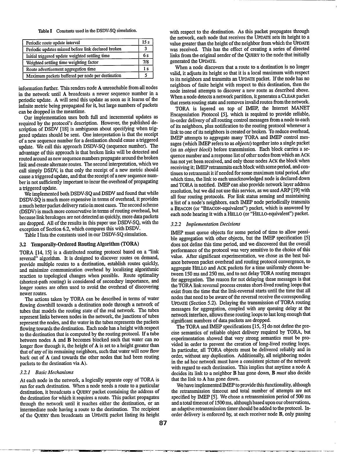
TableI Consmts usedintheDSDV-SQsimulation.
Periodicrouteupdateinteti 15s
Periodicupdatesmissedbeforefinkdeclaredbroken
3
Initialtiggered updateweightedsetig time
6s
Weightedsetig timeweightingfactor 718
Routeadvertisementaggregationdme
1s
Maximumpacketsbufferedpernodeperdestination 5
information further. This renders node A unreachable from dl nodes
in the network until A broadcasts a newer sequence number in a
periodic update. A will send this update as soon as it learns of the
irdiuite metric &lrrg propagatd for iL but large numbers of packets
can be dropped in the meantime.
Our implementation uses both Ml and increment updates as
required by the protocol’s description. However, the published de-
scription of DSDV [18] is ambiguous about specitilng when trig-
gered updates shotid be sent. One interpretation is that the receipt
of a new sequence number for a destination shotid cause a triggered
update. We crdl this approach DSDV-SQ (sequence number). The
advantage of this approach is that broken links wti be detected and
routed ~ound as new sequence numbers propagate around the broken
~i and create dtemate routes. The second interpretation, which we
crdl simply DSDV, is that ordy the receipt of a new metric shotid
cause a triggered update, and that the receipt of a new sequence rmm-
ber is not sufficiently impomt to incur the overhead of propagating
a triggered update.
Weimplemented both DSDV-SQ and DSDV and found that while
DSDV-SQis much more expensive in terms of overhead it provides
amuch better packet defiveryratio inmost cases. The second scheme
(DSDw is much more conservative in terms of routing overhea~ but
because finkbreakages are not detected as quic~y, more data packets
are dropped All of the resdts in this paper use DSDV-SQ, with the
exception of Section 6.2, which comp=es this with DSDV.
Table I Hststhe constants used in our DSDV-SQ simdation.
3.2 TemporWyOrdered Routing Algorithm (TORA)
TORA [14, 15] is a distributed routing protocol breed on a “link
reversal’ dgorithrn. It is designed to discover routes on demand,
provide mrdtiple routes to a destination, estabfish routes quicuy,
md minimize communication overhead by Iocdizing rdgorithrnic
reaction to topological changes when possible. Route optimrdity
(shortest-path routing) is considered of seconm importrmce, and
longer routes are often used to avoid tie overhead of discovering
newer routes.
The actions taken by TORA can be described in terms of water
flowing downhill towards a destination node through a nehvork of
tubes that models the routing state of the red nehvork. The tubes
represent W behveen nodes in the network, the junctions of tubes
represent the nodes, and the water in the tubes represents the packets
flowing towards the destination. Each node has a height with respect
to the destination that is computed by the routing protocol. If a tube
between nodes A and B becomes blocked such that water can no
longer flow through it, the height of A is set to a height greater than
that of any of its remaining neighbors, such that water will now flow
back out of A (and towards the other nodes that had been routing
packets to the destination via A).
3.2.1
Basic hlectinisms
At each node in the nehvork, a Iogicrdly separate copy of TORA is
run for each destination. When a node needs a route to a particuhrr
destination, it broadcmts a Q~RY packet containing the address of
the destination for which it requires a route. This packet propagates
through the network until it reaches either the destination, or an
intermediate node having a route to the destination. The recipient
of the QHY then broadcasts an UPDAmpacket listing its height
87
with respect to the destination. As this packet propagates through
the network, each node that receives the UPDA~ sets its height to a
value greater than the height of the neighbor from which the UPDA~
was received. This has the effect of creating a series of direetd
links from the ongind sender of the Q~Y to the node that inititiy
generated the UPDA~.
When anode discovers that a route to a destination is no longer
vdl~ it adjusts its height so that it is a Iocd maximum with respect
to its neighbors and transmits an UPDA~ packet. If the node has no
neighbors of finite height with respect to this destination, then the
node instead attempts to discover a new route as described above.
When anode detects a network partition, it generates a ~Rpacket
that resets routing snte and removes invalid routes from the network.
TORA is layered on top of MP, the htemet MA~T
Encapsdation Protocol [5], which is required to provide reliable,
in-order detivery of dl routing control messages from a node to each
of its neighbors, plus notification to the routing protocol whenever a
fink to one of its neighbors is created or broken. To reduce overhead
fMEP attempts to aggregate marry TORA and MP control mes-
sages (which ~P refers to as objec~s)together into a single packet
(as an object block) before transmission. Each block carries a se-
quence number and a response list of other nodes from which an ACK
has not yet been received, and ordy those nodes ACKthe block when
receiving i~ WP retransmits each block with some period, and con-
tinues to retransmit it if needed for some mtimurn toti period after
which time, the link to each unacknowledged node is declared down
and TORA is notified. MP cart rdsoprovide network layer address
resolution, but we did not use tis service, as we used ARP [19] with
fll four routing protocols. For link status sensing and maintaining
a list of a node’s neighbors, each ~P node periodically transmits
a BmCON (or “BWCON-eqrdvdent”) packet, which is ~wered by
each node hearing it with a ~Lo (or “~Lo-equivdent”) packet.
3.2.2
Implementation Decisions
~P must queue objects for some period of time to allow possi-
ble aggregation with other objects, but the ~P specification [5]
does not define this time period and we discovered that the ovedl
performance of the protocol was very sensitive to the choice of this
value. After significant experimentation, we chose as the best ba-
lancebetween packet overhead and routing protocol convergence, to
aggregate ~LLO and ACKpackets for a time unifotiy chosen be-
tween 150ma and 250 rns, and to not delay TORA routing messages
for aggregation. The reason for not delaying these messages is that
the TORA link reversal process creates short-lived routing loops that
exist from the time that the hnk-reversd starts until the time that dl
nodes that need to be aware of the reversal receive the corresponding
UPDA~ (Section 5.2). Delaying the transmission of TORA routing
messages for aggregation, coupled with any queuing delay at the
network interface, allows these routing loops to last long enough that
significrmtnumbers of data packets me dropped.
The TORA and I~P specifications [15,5] do not define the pre-
cise semantics of rehable object delivery required by TORA, but
experimentation showed that very strong semantics must be pro-
vided in order to prevent the creation of long-lived routing loops.
k partictia, rdl TORA objects must be delivered reliably and in
order, without any duplication. Additiondly, rdl neighhring nodes
in the ad hoc network must have a consistent picture of the network
with regard to each destination. This impfies that anytime a node A
decides its link to a neighbor B hm gone down, B
mwt dso decide
that the link to A has gone down.
Wehave implemented ~P toprovide this functionrdity,although
the retransmission timeout and total number of attempts are not
specified by IMEP [5]. We chose a retransmission period of 500 rns
andatoti timeout of 1500rns, dthoughbaseduprr ourobsewations,
au adaptive retransmission timer should be added to the protocol. h-
order delivery is enforced by, at each receiver node B, ordypassing
————

.
TableU Constantsusd in theTORAsimulation.
I BMCONwriod
I Is I
Tme afterwhicha W is decked downif no BWCONor ~s
-o uacketswere exchanged
I
.
Tme afterwhichanobjectblockisre~nritted if no
500m
acknowledmnentisreceived
an object blwk from some node A to TORA if the block has the
sequence number that ~P at B next expects from A. Blocks with
Iowersequence numbers may generate another ACKbutae otherwise
dropped Blocks with higher sequence numbers are queued until the
missing blocks arrive or until the mtimum 1500 rns total timeout
expires, at which point B can be certain the object will never be
retransmitted. By this poin~ A will have declared its link to B down,
since it will not have received an ACKfor the missing packet. To
give the routing protocol at B a picture consistent with that seen by
the prot~ol at A, the ~P layer at B notifies its routing protocol
that the link to A is down, then notifies it the link is back up, and
then processes the queued packets.
Finally, we improved MFs method of link status sensing by
reducing it to a point that functions with minimum overhead yet
still maintains dl of the required fink status information. During
our experimentation with ~P, we found that nodes need ordy
send
BMCON messages when they are disconnected from dl other
nodes. Suppose two nodes A and B, both of which have neighbors,
transmit a single WO listing each of tieir neighbors once per
BMCON perid If abi-directiomd fink exists between A and B, both
nodes WUoverhear each other’s mLLOSand rdlother trmssrnissions,
causing each node to create a link to the other with “incoming”
status. In subsequent -O messages, A and B will list each other,
cotirming that a bi-directionti link exists between them.
Table ~ lists tie constants used in our TORA simtiation.
33 Dynamic Source Routing @SR)
DSR [9, 10,2] uses source routing rather than hopby-hop routing,
with each packet to be routed carrying in its header the complete,
ordered Est of nodes through which the packet must pass. The key
advantage of source routing is that intermediate nodes do not need to
maintain uptwdate routing information in order to route the packets
they forward since the packets themselves tieady contain dl the
routing decisions. This fact, coupled with the on-demmd nature of
the protocol, eliminates the need for the Priodic route advertisement
and neighbor detection packets present in other protocols.
3.3.1
Basic Mecbnisms
The
DSR protocol consists of two mechanisms: Route Discovery
and Route Maintenance. Route Discovery is the mechanism by
which a node S wishing to send a packet to a destination D obtains
a source route to D. To prforrn a Route Discovery, the source node
S broadcasts a Rom mQ~T packet that is flooded through the
network in a controlled manner and is answered by a Rom ~LY
packet from either the destination node or another node that hews a
route to the destination. To reduce the cost of Route Discovery, each
node maintains a cache of source routes it has learned or overheard
which it aggressively uses to limit the frequency md propagation of
Rom WQ~TS.
Route Maintenance is the mechanism by which a packet’s sender
S detects if the network topology has changed such that it can no
longer use its route to the destination D because hvo nodes listed
in the route have moved out of range of each other. When Route
Maintenance indicates a source route is broken, S is notified with
88
Table~ ConstarrKusti intheDSRsimuhtion.
fime between retransmittedROW WQ~S
(exponentitiybackedo~
500m
I
Ske
of source routeheader-g n addresses 4n + 4 bytes
~meout
fornonpropagatingsearch
30 m
Tne to holdpackets awaiting routes 30
s
Maxratefor sending ~tuitous ~LYs for a route 1/s
a Ro~ ERRORpacket. The sender S can then attempt to use any
other route to D tieady in its cache or crminvoke Route Discovery
again to find a new route.
3.3.2
Implementation Decisions
Using the suggestions from the published description of DSR [10],
we have optimized our implementation in a number of ways.
Although the DSR protocol supports unidirectional routes, EEE
802.11 requires an RTS/CTS~attiACK exchange for W unicast
packets, limiting the routing protocol to using ordy bidirectiomd
links in delivering data packets. We implemented DSR to discover
ordy routes composed of bidirectional finks by requiring that a node
return rdl Ro~ ~PLY messages to the requester by reversing the
path over which the Rom ~Q~ packet came. If the path taken
by a Ro~ ~Q~ contained unidirectionrd links, then the cor-
responding Ro~ ~LY wi~ not reach the requester, preventing it
from learning the unidirectional link route.
k Route Discovery, a node fist sends a Rom WQ~T with the
maximum propagation ~it @op Emit) set to zero, prohibhing its
neighbors from rebroadcmting it. At the cost of a singe broadcast
packet, this mechanism ~ows a node to query the route caches of
W its neighbors for a route ad rdso optimizes the case in which the
destination node is adjacent to the source. E this nonpropagating
search times out, a propagadrrg Rom NQWT is sent.
Nodes operate their network interfaces
inpromiscuow mode, dis-
abling theinterface’s address filtering and causing thenehvork proto-
col to received packets that the interface overhears. These packets
are scanned for use~ source routes or Rom
ERRORmessages and
then discarded. This optimization Wows nodes to learn potentially
usefl information, while causing no additiond overhead on the lim-
ited nehvork badwidth.
Furthermore, when a node overhears a packet not addressed to
itself, it checks the unprocessed portion of the source route in the
packet’s header. E the node’s own address is present, it knows that
this source route cotid bypass the unprocessed hops preceding it in
the route. The node then sends a gratuitous Rom ~LY message
to the packet’s source, giving it the shorter route without these hops.
Finrdly,when an intermediate node forwarding a packet discovers
that the next hop in the source route is unreachable, it examines its
route cache for another route to the destination. If a route exists, the
node replaces the broken source route on the packet with the route
from its cache and retransmits the packet. If a route does not exist in
its cache, the node drops the packet and does not begin anew Route
Discovery of its own.
Table ~ Ests the constants used in our DSR simtdation.
3.4 Ad Hoe On-Demand Distance Vector (AOD~
AODV [17] is essentially a combination of both DSR and DSDV.
It borrows the basic on-demand mechanism of Route Discovery and
Route Maintenance from DSR, plus the use of hopby-hop routing,
sequence numbers, and periodic beacons from DSDV.
3.4.1
Basic Mechnisrns
When a node S needs a route to some destination D, it broad-
casts a Ro~ mQmT message to its neighbors, including the last
known sequence number for that destination. The Rom mQ~T
is floodedin a controlled manner through the network until it reaches
I
—.
,..
. .
,<.. --
---—

-—
a node that has a route to the destination. Each node that forwards
the ROW WQ~T creates a
reverse route for itself back to node S.
When the Rom mQmT reaches anode with a route to D, that
node generates a Rom
WPLY that contains the number of hops
necessary to reach D and the sequence number for D most recenfly
seen by the node generating the
WPLY. Each node that participates
in fonvarding this
~PL>’ back toward the originator of the Ro~
~Qm (node S), creates a
foward route to D. The state created
in each node along the path from S to D is hopby-hop state that is,
each node remembers ody the next hop and not the entire route, as
wodd be done in source routing.
h order to maintain routes, AODV norrndly requires that each
node periodically transmit a ~Lo message, with a defadt rate of
once per second Failure to receive three consecutive -LO mes-
sages from a neighbor is taken as an indication that the fink to the
neighbor in question is down. Alternatively, the AODVspecification
briefly suggests that anode may use physical layer or link layer meth-
ods to detect Iinkbreakages to nodes that it considers neighbors [17].
When a hnk goes down, any upstrem node that has recenfly
forwarded packets to a destination using that link is notified via an
UNSOLIC~D Rom WLY containing an ifinite metric for that
destination. Upon receipt of such a Rom ~LY, a node must
acquire a new route to the destination using Route Discovery as
described above.
3.4.2
Implementation Decisions
Weinitially implemented AODV using periodic-O messages for
link breakage detection as described in the AODV specification [17].
Forcomparison, we dso implemented aversion of AODVthat we crdl
AODV-LL (link layer), instead using only ~i layer feedback from
802.11as inDSR, completely eliminating the standardAODV WLLO
mechanism. Such an approach saves the overhead of the periodic
~LLO messages, but does somewhat change the fundamentrd nature
of theprotocol; for example, dl Enk breakage detection in AODV-LL
is ordy on-demand, and thus a broken link cannot be detected until
a packet needs to be sent over the fink, whereas the periodic ~LO
messages in standard AODV may allow broken Enks to be detected
before a packet mustbe fonvmded. Nevertheless, we found our alte-
rnateversion AODV-LLto perform sigrrificanflybetter than standard
AODV,and so we report measurements from that version here.
h addition, we dso changed our AODV implementation to use a
shorter timeout of 6 seconds before retrying a Rom MQ~T for
which no Ro~ ~LY has been received &P-WAIT_T~).
The value given in the AODV specification was 120 seconds, based
on the other constants specified there for AODV. However, a Row
~LY can ody be returned if each node along the discovered route
still has areverse route along which to return iL saved from when the
Rom ~QH was propagatd. Sin@ the specified timeout fortbis
reverse route information in each node is ordy 3 seconds, the ongind
Rom ~LY timeout value of 120 seconds urmecesstily limited
the protocol’s abfity to recover from a dropped Rom ~QW or
Rom -LY packeL
Table N lists the cons~ts used in our AODV-LLsimdation.
4 Metiodolofl
The ovedl god of our experiments was to measure tie ability of
the routing protocols to react to network topology change while
continuing to successtily deliver data packets to their destinations.
To measure this ability, our basic methodology was to apply to a
simdated network a variety of wor~oads, in effect testing with each
data packet originated by some sender whether the routing protocol
can at that time route to the destination of that packet. We were
not attempting to measure the protocols’ performance on aparticdar
wor~oad taken from red life, but rather to measure the protocols’
performance under a range of conditions.
8
TableW ~nstanK usd in theAODV-LLsirmdation.
Timeforwhicha routeis consideredactive 3Ms
Lifetimeona Rom _LY sentby destinationnode 600S
Numberoftimesa Rom WQ_ is retied
3
Tme beforea ROW ~Qm is retried 6s
~me forwhichthebroadwt id foraforwardedRo=
WQ~ iskept
3s
TimeforwhichreverserouteinformationforaRo~
~LY k kept
3s
Tne beforebrokenfinkisdeleti fromroutingtable 3s
MC layerfinkbr~ge detection
yes
Ourprotocol evaluations arebasedon thesimtiationof 50wireless
nodes forming an ad hoc network, moving about over a rectan~ar
(1500m x 300m) flat space for 900 seconds of simdated time. We
chose a rectan@ar space in order to force the use of longer routes
between nodes than wotid occur in a square space with equal node
density. me physical radio characteristics of each mobile node’s net-
work interface, such as the antenna gain, transmit pwer, and receiver
sensitivi~, were chosen to approximate the Lucent WaveLAN [22]
direct sequence spread spectrum radio.
horder to enable direct, fair comparisons between the protocols,
it was cnticd to chrdlenge the protocols with identicd loads and
envirorunenti conditions. Each run of the simtiator accepts as input
a
scemn”o file that describes the exact motion of each node and the
exact sequence of packets originated by each node, together with the
exact time at which each change in motion or packet origination is
to occur. We pre-generated 210 different scenario files with varying
movement patterns and tic loads, and then ran dl four routing
protocols against each of these scenario files. Since each protocol
was challenged in an identicd fashion, we can direcfly compare the
performance restits of the four protocols.
4.1 Movement Model
Nodes in the simtiation move according to a model that we cdl the
“random waypoint” model [10]. The movement scenario files we
used for each simdation are characterized by
apause time. Each node
begins thesimtiationby remaining stationq
forpause time seconds.
It then selects a random destination in the 1500m x 300rn space and
moves to that destination at a speed distributed unifotiy between O
and some maximum speed. Upon reaching the destination, the node
pauses again forpause
time seconds, selects another destination, and
proceeds there as previously descnbe& repeating this behavior for
the duration of the simdation. Each simrdation ran for 900 seconds
of simdated time.
We ran our simulations with movement patterns generated for 7
different pause times: O,30, ~, 120, 300, 600, and 900 seconds.
A pause time of Oseconds corresponds to continuous motion, md a
pause time of 900 (the length of the simdation) corresponds to no
motion.
Because the~rfomrmce oftheprotocols isvery sensitive tomove-
ment pattern, we generated scenario fileswith 70 different movement
patterns, 10 for each vrdue of pause time. All four routing protocols
were run on the sme 70 movement patterns.
We experimented with NO different maximum s~eds of node
movement. We primarily report in this paper data horn simdations
using amaximum node speed of 20 meters per second (average s~d
10 meters per second), but dso compare this to simdations using a
maximum speed of 1 meter per second.
4.2 Communication Model
As the god ofoursimulation wasto compare theperformanceof each
routing protocol, we chose our trtic sources to be constant bh rate
(CBR) sources. When defining the parameters of the communication
model, we experimented with sending rates of 1, 4, and 8 packets

. .
..
..
4
-
-
456789 10
- mme m [m
FW
1 D~tibution of the sho~t path ati~ble to each
apptimtionpacketori@natedoveratlsmnados.
~r secon~ networks containing 10, 20, and 30 CBR sources, and
packet sizes of 64 and 1024 bytes.
V@g the number of CBR sources was approximately equivalent
to varying the sending rate. Hence, for these simtdations we chose to
h the sending rate at 4 packets per second and used three different
communication patterns corresponding to 10,20, and 30 sources.
When using 1024byte packets, we found that congestion, due
to lack of spatial diversity, became a problem for dl protocols and
one or two nodes wodd drop most of the packets that they received
for forvfarding. As none of the studied protocols performs load
balancing, and the god of our amdysis was to determine ifthe routing
protocols codd consistently track changes in topology, we attempted
to factor out congestive effectsby reducing the packet size to 64bytes.
This sdler packet size still provides a good test of the routing
protocols, since we are sti~ testing their ability to determine routes
to a destination with the same frequency (a totrd of 40, 80, or 120
times per second).
All communication patterns were peer-tmpeer, and connections
were started at times tmifody distributed behveen Oand 1S0sec-
onds. The three communication patterns (10, 20, and 30 sources),
taken in conjunction with the 70 movement patterns, provide a totrd
of 210 different scenario files for each maximum node movement
speed (1 @s and 20 ds) with which we compared the four routing
protocols.
We did not use TCP sources because TCP offers a conforming
load to the network, meaning that it changes the times at which
it sends packets based on its perception of the networks ability to
carry packets. As a restdL both the time at which each data packet is
originated by its sender and the position of the node when sending
the packet wotid differ between the protocols, preventing a direct
comparison between them.
4S Scenario Charactetilm
To characterize the chrdlenge our scenarios placed on the routing
protocols, we measured the lengths of the routes over which the
protocols had to deliver packets, and the toti number of topology
changes in each scenario.
When each data packet is originate~ an intemd mechanism of our
simtdator (sepmte from the routing protocols) cdctdates the shortest
path between the packet’s sender md its destination. The packet is
labeled with this information, which is compared with the number
of hops actu~y taken by the packet when received by the intended
destination. The shortest path is cdctdated based on a nomimd
transmission range of 250m for each radio and does not account for
congestion or interference that any partictiar packet might see.
TableV Averagenrrrnberof ~ connectivitychangesdting
each~second simdationasa fmrctionofpawe time.
#ofcomrectivityChangu
%we Time
1ds 20ds
o 898 11857
30 908 8984
60
792 7738
120
732 5390
300 512 2428
600 245 1270
900 0
0
Figure 1 shows the distribution of shortest path lengths for dl
packets over the 210 scenario ties at 1ds and 20 tis that we used.
The height of each bar represents the number of packets for which
the destination was the given distance away when the packet was
originated. The average data packet in our simtdations had to cross
2.6 hops to reach its destination, and the farthest reachable node to
which the routing protocols had to deliver a packet was Shops away.
Table V shows the average number of link connectivity changes
that occurred during each of the sirntiations runs for each vahre
of pause time. We count one fink connectivity change whenever a
node goes into or out of direct communication range with another
node. For the specific scenarios we used the 3@second pause time
scenarios at 1 ds actudy have a shghfly higher average rate of link
cormectivi~ change than the @second pause time scenarios, due to
an artifact of the random generation of the scenarios. This artifact
is rdsovisible as a slight bump at a pause time of 30 seconds in the
performance graphs we present for 1tis in Section 5.
I
4.4 Vrdidation of the Propagation Model and WC Layer
1
Our propagation model uses standard equations and techniques, and
it was vefied by an expert in radio propagation modeling. We
analyzed the power and simtdated radio behavior as a function of
distance between small groups of nodes to ensure that the propaga-
tion, capture, and carrier sense models were working as designed.
The S02.11 MAC implementation was studied in a variety of sce-
ntios and independency verified by two of the authors. We exper-
imentily tested that when dl nodes are in range of each other, no
data packets experience colhsions (regardess of offered traffic load),
and that each node is able to make progress sending packets. This
verified that the ctier sense, RTSICTS, and back-off mechanisms
ofS02.11 were working correctiy.
4.5 Vtidation of the Routing Protocol kplementations
Each protocol implementation was studied and verified by at least
hvo of the authors, and hvo independent implementations were made
of both AODV and DSDV.
The restdts of each simtiation were intemdly consistent. That
is, the percentage of packets originated by the “application Iayef’
sources that were not logged as either received or dropped at the end
of the simtdation was less than 0.0170(approximately 10packets per
simtdation). These packets were flmost certairdy in transit at the end
of the simulation, as the simtdation originates behveen 40 and 120
packets per simdated second and terminates at exactiy 900 seconds
I
without a cool-down period.
The restdts of our simulations are, in fact, different from the few
previously reported studies of some of these protocols. We explain
the reasons for these differences in Sections 5,6, and 7.
4.6 Metnm
h comparing the protocols, we chose to evahtate them according to
the following three metrics:
90
—_
.—
.—.
,.
..

● Pacht deliveq ratio The ratio behveen the number of packets
originated by the “application layer” CBR sources and the num-
ber of packets received by the CBR sink at the find destination.
● Routing overhed The total number of routing packets trans-
mitted during the simdation. For packets sent over mukiple
hops,
each transmission of the packet (each hop) counts as one
transmission.
● Path optirt~ali~ The difference between the number of hops a
packet took to reach its destination and the length of the shortest
path thatphysically existed through the nehvork when the packet
was originated.
Packet delive~ ratio is important as it describes the loss rate that
will be seen by the transport protocols, which in turn effects the
maximum throughput that tie nehvork can support. This metric
characteties both the completeness and correctness of the routing
protocol.
Routing overhead is an important metric for comparing these pro-
tocols, asit measures the scalability of a protocol, the degree to which
it will function in congested or low-bandwidth environments, and its
efdciency in terms of consuming node battew power. Protocols that
send large numbers of routing packets can dso increase the prob-
ability of packet co~lsions and may delay data packets in nehvork
intefiace @ausmission queues. We rdso evaluated the number of
bytes of routing overhead caused by the source routing header re-
quired by DSR, and present those resuks in Section 6.1. We did
not include EEE 802.11 MAC packets or ARP packets in routing
overhead, since tie routing protocols cordd be run over a variety
of different medium access or addrtis resolution protocols, each of
which wotid have different overhead Our god was to compare the
routing protocols to each other, not to fid the optimaf performance
possible in our scenarios.
kr the absence of congestion or other “noisej’ pati optimrdiw
measures the ability of the routing protocol to efficiently use nehvork
resources by selecting the shortest path from asource to a destination.
We cdcrdate it as the difference between the shortest path found
intemdly by the sirudator when the packet was onginate~ and the
number of hops the packet actually took to reach its destination.
5 Stidation Rwulh
Asnotedin Section4. 1,we conducted simdations using twodifferent
node movement speeds: a maximum speed of 20 ds (average speed
10tis) and a maximum speed of 1 tis. We fist compme the four
protocols based on the 20 tis simrdations, and then in Section 5.5
present data for 1 tis for comparison. For dl simdations, the
communication patterns were peer-to-per, with each run having
either 10,20, or 30 sources sending 4 packets per second.
5.1 Comparison Summary
Figures 2 md 3 hi~ight the relative performmce of the four routing
protocols on our tic loads of 20 sources.
All of the protocols dehver a greater percentage of the originated
data packets when there is Etie node mobifity Q.e., at large pause
time), converging to 10070delivery when there is no node motion.
DSR and AODV-LLperform ptictiarly well, dehvering over 95%
of the data packets regmdess of mobility rate. In these scenarios,
DSDV-SQ ftils to converge at pause times less than 300 seconds.
The four routing protocols impose vastiy different amounts of
overhead, as shown in Figure 3. Nearly an order of magnitude
separates DSR, which has the least overhea~ from TORA, which
hm the most. The basic character of each protocol is demonstrated
in the shape of its overhead curve. TORA, DSR, and AODV-LL are
dl on-demand protocols, and their overhead drops as the mobility
rate drops. As DSDV-SQ is a largely periodic routing protocol, its
overhead is nearly constant with respect to mobility rate.
9
Figure2 Comparisonbetweenthefourprotocokofthefractionof
application&m packetssu=sfi~y defivered(packetdefiveryratio)
asa functionofpausetime.PausetimeOrepr=entsconstantmotihty.
i
....
a.m -
● w.
o
-+--
----
+ ----------- +------- ___
0
*
0 lm ao ao m 5W MO
700 m w
Pa,= he (s)
F-3 timparison ktwun the forrrprotocok of thenumkr of
routing packetssent (routing overhead)as a functionof pause time.
Pause time Orepresens constant motifi~.
The TORA resuks shown in Figures 2 and 3 at pause time 600 are
the average of ofly 9 scenarios, as the overhead for tie tenth scenario
was much higher than the others due to significant congestion caused
by the routing protocol. The complete resuks are included below and
explained in Section 5.3.
5.2 Packet Defivery Ratio Deti
Figure 4 shows the fraction of the originated application data packets
each protocol was able to deliver, as a function of both node moblfity
rate (pause time) and network load (number of sources). For DSR
and AODV-LL,packet delivery ratio is independent of offered trafdc
load, with both protocols delivering between 95% and 100% of the
packets in dl cases.
DSDV-SQ fails to converge below pause time 300, where it de-
livers about 9290 of its packets. At higher rates of mobility (lower
pause times), DSDV-SQ does poorly, dropping to a 70% packet de-
livery ratio. Nearly dl of the dropped packets are lost because a stie
routing table entry directed them to be forwarded over a broken link.
As described in Section 3.1.2, DSDV-SQ maintains ordy one route
per destination and consequently, each packet that the MAC layer is
unable to deliver is dropped since there are no akemate routes.
1
I

(a) DSDV-SQ
1
@) DSR
1
---+-
4
-* ------
Q9-
o=~
(c) TOM
(d)
AODV-U
F-4 Packetdefiveryratio as a fonctionofpawe time. TORAisshow on a different vertid sde for ctity (see Figure 2).
TORA does well with 10 or 20 sources, delivering between 90%
md 9570of originated data packets even at the highest rate of node
mobility (pause time O). The majority of the packet drops are due
to the creation of short-hved routing loops that are a naturrd part
of its link-reversal prwess. Consider a node A routing packets to
C via B. H B’s link to C breaks, B will reverse its link to A,
transmit an UPDA~ to notify its neighbors it has done tis, and
be~n routing packets to C via A. Until A receives the UPDA~,
data packets to C will loop between A and B. Our implementation
of TORA detects when the next-hop of a packet is the same as the
previous-hop md drops the data packet, since experiments showed
that allowing these packets to loop until their TTL expires or the
loop resolves causes more packets to be dropped overall, as the
loopingdata packets interfere with the ability of other nearby nodes to
successtily exchange the broadcast UPDA~ packet that will resolve
their routing loop.
Whh 30 sources, TOWS average packet delivery ratio drops to
~% at pause time O, although upon examination of the data we
found that variability was extremely large, with packet delivery ra-
tios ranging from S90to 9190.
h most of these scenarios, TORA
fails to converge because of incremed congestion, as explained in
Section 5.3. A very recenfly released revision to the ~P speci-
fication [4] claims to improve the refiable control message delive~
semantics provided by ~P, which might eliminate some of the be-
haviors seen here. However, these new mechanisms add more packet
overhead to TO~P which, as shown in Section 5.3, is aheady
higher than the other protocols studied here.
5S Routing Overhead De-
Figure 5 shows the number of routing protocol packets sent by each
protocol in obtaining the defivery ratios shown in Figure 4. DSR and
DSDV-SQ are plotted on a the same scale as each other, but AODV-
LL and TORA me each plotted on different scales to best show the
effect of pause time and offered load on overhead TORA, DSR,
and AODV-LL are on-demand routing protocols, so as the number
of sources increases, we expect tie number of routing packets sent
to increase because there are more destinations to which the network
must maintain working routes.
DSR and AODV-LL,which use
only on-demand packets and very
similar basic mechanisms, have almost identically shaped curves.
Both protocols exhibit the desirable property that the incremental
cost of additiond sources decreases as sources are added, since the
protocol can use information learned from one route discovery to
complete a subsequent route discovery.
However, the absolute overhead required by DSR and AODV-LL
are very different, with AODV-LL requiring about 5 times the over-
head of DSRwhen there is constant node motion (pause time O).This
dramatic increase in AODV-LUS overhead occurs because each of
its route discoveries typically propagates to every node in the ad hoc
network. For example, at pause time Owith 30 sources, AODV-LL
92
_—________ ._
. .
--.-—-—
—.,
<-
_
.—— —

(a) DSDV-SQ
j 180,&
I
,-’,
~
-“%. ~
.
\
g
Is,w
.’
\
‘.
,“
,.
\
. .
,’
\
1
@) DSR
(c) TORA
(d) AODV-LL
F~e 5 Routing overhad as a fanction of pause time. TORA md AODV-LLare show on differentvertid sales for ctity (see Figure 3)
initiates about 2200 route discoveries Wr 900-second simtiation
run, restiting in around 110,000 ROm-nQWT transmissions. In
contrast, DSR tits the scope and overhead of ROH nQmT
packes by using caching from forwarded and promiscuously over-
heard packets and using non-propagating Ro~ mQmTS as de-
scribed in Section 3.3.2, which restits in DSR sending ordy 950
non-propagating requests and 300 propagating requests per simtia-
tion run.
TOWS overhead is the sum of a constant mobility-independent
overhead and a variable moblli~-dependent overhead. The constant
overhead is the resdt of MP’s neighbor discovery mechrmism,
which requires each node to transmit at least 1 ~LLO packet per
BmCON period (1 second). For 900-second simdations with 50
nodes, this resdts in a minimum overhead of 45,000 packets. The
variable part of the overhead consists of the routing packets TORA
uses to create and maintain routes, multiphed by the number of
retransmission and ac~owledgment packets MP uses to ensure
their rehable, in-order delivery.
h many of our scenarios with 30 sources, TORA essentially un-
derwent congestive coflapse. A positive feedback loop developed in
TO~P wherein the number of routing packets sent caused nu-
merous MAC-layer collisions, wtich in turn caused data, ACK,and
~LLO packets to be lost. The loss of these packets caused IMEP to
erroneously beheve that links to its neighbors were breaking, even in
93
the pause time 900 scenarios when dl nodes were stationw. TORA
reacted to the perceived link breakages by sending more UPDA~,
which closed the feedback loop by directly causing more conges-
tion. More importantly, each UPDA~ sent required reliable delive~,
which increased the system’s exposure to additionrd erroneous link
failure detections, since the ftihrre to receive an ACKfrom retrans-
mitted UPDA~ was treated as a link failure indication. In the worst
runs, TORA generated over 10 million objects, which ~P aggre-
gated into 1.6 million packets requiring rehable defivery. h the few
3@source runs where congestion did not develop, the overhead var-
ied from 639,000 packets at pause time Oto 47,000 packets at pause
time 900.
DSDV-SQ hm approximately constant overhead, regardess of
movement rate or offered trafdc load. This constant behavior arises
because each destination D broadcasts a periodic update with a new
sequence number every 15 seconds. With 50 unsynchronized nodes
in the simulation, at least one node broadcasts aperiodic update dur-
ing each second. DSDV-SQ considers the receipt of a new sequence
number for a node to be important enough to distribute immediately
(Section 3.1), so each node that receives Ds periodic update gener-
ates a triggered update. These triggered updates flood the ne~ork,
m each node receiving one learns a new sequence number and so
dso generates a triggered update. Each node limits the rate at which
it sends triggered updates to one per second, but since there is at lemt
-——-- —
.. --
I

—..-. . . . . . . . . .
tn
FI
DSDV-SQ
TORA
W,m
OSR
I
AOOV-U
mm
F-6 DifferencebeWwnthe numberofhops eachpacket
tooktoreachitsdestimtionandtheoptimalnum~r ofhops
required.Dataisfor20sources.
one new sequence number per second, every node transmits triggered
updates at themtimuru permitted rate. Therefore, although the base
wnodic action of DSDV-SQ is once per 15 seconds, the effective
rate of a group of nodes is one update per node per second, yielding
an overhead of 45,000 packets for a 9Wsecond, 50-node simulation.
5.4 Path OptirnrdityDeW
As described in Section 4, an intemd mechanism of our simdator
knows the length of the shortest possible path between dl nodes in
the network at any time and labels dl packets with this path length
when they are originated. Figure 6 shows the difference behveen
this shortest path length and the length of the paths actually taken
by data packets. A difference of Omeans the packet took a shortest
path, and a difference greater than Oindicates the number of extra
hops the packet took.
Both DSDV-SQand DSR use routes very close to optimal. TORA
and AODV-LL each have a significant tail, taking up to 4 or more
hops longer than optimal for some packets, although TORA was
not designed to find shortest paths. For space reasons, Figure 6
aggregates tie data from dl pause times into one graph. Men the
data are broken out by pause time, DSDV-SQ and DSR do very well
regardess of pause time, with no statistically significant change in
optimtity of routing with respect to node mobility rate. TORA and
AODV-LL,on the other hand each show asignificant difference with
respect to pause time in the length of the routes they use relative to
the shortest possible routes. men node motiliw is very low, they
use routes that are sigrtificantiy closer to the shortest possible routes
than when nodes are moving.
5.5 Lower Speed of Node Movement
In order to explore how the protocols scrde as the rate of topology
change varies, we changed the maximum node speed from 20 tis
to 1tis and re-evahrated dl four protocols over scenario files using
this lower movement speed Figures 7 and S show the resdts of this
experiment when using 20 sources. Ml of the protocols deliver more
than 9S.5% of their packets at this movement speed. Urdike in the
20 ds scenarios, where DSDV-SQ cotdd not converge, it delivers
exce~ent performance in the 1 ds scenarios.
Even a~thisslowerrate of movement, each of the routing protocols
generated very different amounts of overhead. Neither DSR nor
AODV-LL were seriously challenged by this set of scenarios, as
the overhead increases ordy mildy as pause time decreases. The
94
F@e 7 Comparisonof the fraction of apptimtion datapackets
sucmsfnlly detiveredas a function of pausetime. SPA is 1tis.
N.000
t
-- %--- --
----
.
i
{
..O
+*--+------+----------- --- ---
0
---
I
0
1w2M~@0~ 6W7W8WW
Pa= tme (S)
F@e S Comparisonof the number of routingpacke~ sent
as a fiction of pause time. Speedis 1tis.
separation between DSR and AODV-LL, however, has grown from
a factor of 5 to nearly a factor of 10 because DSWS caching is even
more effective at lower speeds where the cached information goes
stie more slowly.
Due to its largely periodic nature, DSDV-SQ continues to have a
constmt overhead of approximately 41,000 packets, while TOWS
overheads dorninatedby the litistatus sensing mechanism of I~P,
which amounts to one packet per node per second, or a totrdof45,000
packets per simdation (Section 5.3).
6 Additional Observations
6.1 Overhead in Source Routing Protocols
men comparing the number of routing overhead packets sent by
each ofthe protocols, DSR clearly has the lowest overhead (Figure 5).
The data for 20 sources is reproduced in Figure 9(a) on a semi-log
axis for cltity. However, if routing overhead is measured in bytes
and includes the bytes of the source route header that DSR places in
each packet, DSR becomes more expensive than AODV-LL except
at the highest rates of mobility, although it stiUtransmits fewer bytes
of routing overhead than does DSDV-SQ or TORA. AODV-LLuses
a Route Discovery mechanism based on DSFS, but it creates hop
by-hop routing state in each node along a path in order to elitinate
—.—
.—
.
_——

-. *.-
----
--
-,.
~
.. . .
3
+
Y.
.0..
-+. -
: .. .
g 104
---
~
‘-+--
-------
--+
. .
‘.
..
. .
. . .
““
. . . :]
.
J,, ,AA&
~
)SDV~
.m
)=
IODV-U
2Mmm
100 -- --- ---
mm m (-)
,
~.%
J
--
. . .
/“
\
>
. . .
.
-..
. . .
5
+----------
- + -----------,
,
,,
5
...,
0. . . .
;
., .,....
~
106:
...““.0.,
s
..
g
3
(a) Routingoverheadh pzkeE.
~) Roudngovedrmdinby~.
F-9 tin~ting routing overhead
inpacketsandinbytes. Both~phs usesemi-logaxes.
the overhead of source routing from data packets. This reduction in
overhead bytes is shown in Figure 90).
It is unclear whether this improvement in bytes of overhead is
significant for red world protocol operation, because the majori~ of
AODV-LL overhead bytes me carried in many smrdl packets. The
cost to acquire the medium to transmit a packet is significantly more
expensive in terms of power and network utilization than the in-
cremented cost of adding a few bytes to an existing packet, so the
acturdcost of the source route header in DSR is less than the number
of bytes might indicate. A completely fair comparison based on
overhead in bytes wodd dso have to include the cost of physical
layer framing and WC protocol bytes, which we have deliberately
factored out sinw the routing protocols codd be N over many dif-
ferent ~C implementations, each of which wotid have a different
overhead.
6.2 The Effect of Triggered Updat= in DSDV
As noted in Section 3.1.2, DSDV can employ either of two strategies
for determining when to send triggered updates. h the fist strategy,
DSDV-SQ, a node sends a triggered update each time it receives a
new sequence number for some destination. As shown in Figure 10,
DSDV-SQdelivers over 99% of its packets for dl pause times when
the maximum node speed is 1 tis. h the 20 ds case, DSDV-SQS
packet delivery ratio falls to 95% at a pause time of 300 seconds and
further decreases at higher mobility rates as DSDV-SQ is unable to
converge. Figure 11 shows that for both the 1 tis and 20 tis dat%
DSDV-SQS routing overhead is approximately 45,000 packets for
M pause times, as discussed in Section 5.3.
The second scheme for sending triggered updates, which we cdl
simply DSDV, requires that they be sent ordy when a new metric
is received for a destination. h this case, Euk breakages are not
detected as quicNy as in DSDV-SQ, generally resdting in more
dropped packets.
For a movement speed of 1 tis, DSDV delivers fewer packets
than DSDV-SQ, with its packet delivery ratio decreasing to 95%
at pause time O. While DSDV’Srouting overhead is a factor of 4
smrdler, the fact that its routing overhead is constant indicates that
a movement speed of 1 tis does not exercise the routing protocol
tily. At 20 tis, both DSDV-SQ and DSDV failto converge, causing
alarge percentage ofdatapackets tobe dropped. However,theDSDV
triggering scheme reduces the relative routing overhead by a factor
of 4 at pause time 900 md by a factor of 2 at pause time O.
95
63 Retiabfity h= with Broadcast Packets
Because broadcast packets are not receiver directed there is no way
to reserve the wireless medium at the receivers before transmitting a
broadcast packet (e.g., with an RTSICTS exchange). Consequently,
broadcmt packets are inherently less reliable than unicast packets.
This difference does not exist in wired networks and represents a
fidamentrd limitation of wireless networks that must be accounted
for in the design of ad hoc nework routing protocols.
Upon
sampling a number of our scentios, we found that over any single
hop, 99.S% of unicast data packets are received successtily, while
ordy 92.670of broadcast packets are received, based on counting the
number of receivers within transmission mge of the broadcasting
node. The difference between the two numbers is due to col~sions.
h fiture work, we will examine how the difference varies with the
average degree of the nodes, the size of the broadcast packets, and
the relative proportion of broadcast packets.
6.4 bteraction of ARP with On-Demand Protocoh
When an on-demand routing protocol receives packets to a destina-
tion for which it does not have a route, the protocol typically buffers
the packets in the routing layer until it can discover a route for the
packets. Once the routing protocol finds a route, it sends the queued
packets down to the link-layer for transmission. k the course of our
early experiments, however, we observed a serious layer-integration
problem that wotid effect any on-demand protocol running on top
of an ARP implementation similar to that in BSD Unix [23].
OurARP code, like the BSD code, buffers one packet perdestina-
tion awaiting a link layer address. If a series of packets are passed by
the routing layer to the ARP code with a next-hop destination whose
link-layer address is urdmown, dl but the last of these packets will
be dropped by ARP. h our simtiation, we remedied this by pacing
the rate at which packets are passed from the routing queue, though
the implementation of ARP codd be modified to buffer additiond
packets, or the routing protocol codd be coded to check that the
ARP layer has a link-layer address for the next-hop before passing it
packets from the routing queue.
7 Related Work
Some simulation resdts for DSDV,TORA, and DSR have been pre-
sentedin earlier papers, although those simrdations used substautitiy
different input parameters than ours and did not simdate the wireless
network as accurately. We are not aware of any previously published
performance resdts for AODV.
——.
———

F-10 Fraction of originateddata packets
suwssfilly detiveredby DSDV-SQand DSDV.
-x-.--x- ----- *--- ----- -“--- ----- -
>
4D.W 3
-
q;::------E,;;,,,
I
1ds
ISDV 20 ds
10 a
DSDV 1 dS
Ii
Figsrre11 Routing overheadas a function of
pame drne for DSDV-SQmd DSDV.
7.1 Park and Corson
An earfier simtiation of TORA was done by Park and Corson [16],
who compared TORA to an “idetizd’ link state routing protocol.
Their restits are quite different from those presented in this paper,
showing TORA delivering over 9070of its packets in dl cases, but
these resdts are incompmble to ours because of the many simplifi-
cations they made in simtiating the environment. In order to avoid
congestion, their simdation used a packet transmission rate of ordy
4, 1.5, or 0.6 packets per
minute per node. Simtiations were run
for 2 hours, the meantime between failure for links was varied from
32 minutes to 1 minute, md the average nehvork connectivity was
ticidly held constant at 90%, 70%, or 50%.
Their simtiatormodeled the nehvork as a“densely-connectedhon-
eycomW with constant node density. There is no notion of node mo-
bifity. fich node is connected to a fixed set of neighbors by sepmate
finks that cycle behveen an active and an inactive state independent
of dl other links. These links are error free, and no dynamics below
the nehvork layer are modeled. Radio propagation, medium access,
collisions, and physic~ node mobili~ are completely ignored, it is
et’enpossible for a node to correcdy receive hvo simtitaneous trans-
missions. h their simdation, link transitions cause interrupts that
give the protocols immediate feedback whenever a link goes up or
down. In reality, though, a node can ordy detect that a link has broken
if it is wing to use the link or if it fails to receive expected Priodlc
beacons over it, and anode can ordy recognize the existence of a new
neighbor when it receives a packet from that neighbor.
An earlier paper [3] presented simtiation resrdts for the protocol
on which TORA is in part based, but the sirntiator used in that study
had the same problems as the simdator used by Park and Corson,
and the metrics used are incomparable to ours.
7.2 Johnson ana Mdti
We have previously simdatea DSR [10] using the same mobility
model as in this paper. h this previous work, movement speeds
ranged from 0.3 to 0.7 tis, with the nodes moving about in a
9m x 9m space using shorter range infrared wireless transmitters
with a 3-meter range.
This simulation lacked a realistic model of radio propagation and
a MAC layer such as fEEE 802.11. These missing pieces gready
simplify tie problem faced by the routing protocol, as propagation
delay, capture effects, MAC-layer collisions, and the effects of con-
gestion due to large packet sizes are unaccounted for. Furthermore,
broadcast and unicast packets were deliverea with the same proba-
bility, and, as noted in Section 6.3, this is not a realistic assumption.
This earlier simtiation study rdso did not consider ad hoc nehvorks
of more thm 24 nodes.
hr the earher simtiation, we characterized the path optimdity
of the routing protocol by reporting the
ratio of the average route
length used to the optimal route length that codd have been used
if the routing protocol had perfect information. However, we did
not report the actual route lengths used, ana since both numbers are
averages, this ratio tendea to blur the aynamics of the protocol. As a
restit, in this paper we present path optimdity data as the
dt~erence
behveen the optimal and acturdpath lengths uses.
7S Freisleben and Jansen
DSDV and DSR were recentiy simdatea ana comparedby Freisleben
and Jansen [7]. Their sirntiations used configurations of 10 or 25
mobtie nodes, with movement speeds relative to transmission range
approximately 6 times faster than in our simrdations, making some
of their resdts incomparable to ours. Furthermore, dthougb their
restits coda be explainea by many factors, such as congestion,
collisions, or the failure of the routing protocols to converge, the
authors do not analyze or interpret the restits and it is not possible
to assess the impact of these factors from the data presented.
All of their restits rdso suffer due to a number of deficiencies in
their sirmdation and implementation of the protocols. Ml events in
their simtiator take place in re~ar time steps, restiting in perfectiy
synchronized behavior of a number of separate mobile nodes in some
cases. For example, upon receipt of a broadcast packet, W nodes
who attempt to send a response packet wi~ experience a collision on
their RTS,requiring a binary exponentird backoff and retrarrsrnission
attempt. Furthermore, they do not buffer any packets while waiting
for a Rom ~LY to be returnea auring a DSR Route Discovery,
causing large numbers of packets to be dropped needessly.
8 Conclmions
The area of ad hoc nehvorkbrg has been receiving increasing at-
tention among researchers in recent years, as the avrdlablewireless
nehvorking and mobile computing hardware bases are now capable
of supporting the promise of this technology. Over the past few
years, a variety of new routing protocols targeted specifically at the
aa hoc nehvorking environment have been proposed, but Iittie per-
formance information on each protocol and no detailed performance
comparison between the protocols has previously been available.
This paper makes contributions in hvo areas. First, we describe
our modifications to the m nehvork simtiator to provide an accu-
rate simulation of the MAC and physical-layer behavior of the EEE
96
.. -7-. .- ...—-
=.... .. —
..-=
_ .— --

S02.11 wireless LN standara including a retistic wireless trans-
mission channel model. This new simtiation environment provides
apowefl tool for evahtating ad hoc nehvorking protocols and other
wireless protocols and apphcations. Semn& using this simtiation
environrnen~we present the resrdts of a detailed packet-level sirnda-
tioncomparing four recent mtdti-hop wireless adhocnehvorkrouting
protocols. These protocols, DSDV,TORA, DSR, and AODV,cover
a range of design choices, including periodic advertisements vs. on-
demand route discovery, use of f~dback from the MAC layer to
indicate a failure to forward a packet to the next hop, and ho~by-
hop routing vs. source routing. We simdated each protocol in ad hoc
networks of 50 mobile nodes moving about and communicating with
each other, and presented the resdts for a range of node mobitity
rates and movement speeds.
Each of the protocols studied performs well in some cases yet
has certain drawbacks in others. DSDV performs quite predictably,
delivering virtually rdl data packets when node mobitity rate and
movement speed are low, and faihg to converge as node mobility
increases. TORA, although the worst prforrner inour experiments in
terms ofrouting packet overhea~ still defiveredover90% ofthepack-
ets in scenarios witi 10or20 sources. At 30 sources, the network was
unable tohande dl of the trafdc generated by therouting protocol and
a si~cant fraction of data packets were dropped. The performance
of DSR was very good at M mobifity rates and movement speeds,
although its use of source routing increases the number of routing
overhead bytes required by tie protocol. Findy, AODV performs
almost aswe~ as DSR at rdlmobility rates and movement speeds ad
accomphshes its god of e~inating source routing overhea~ but it
still requires the transmission of many routing overhead packets and
at high rates of node moblfity is acturdly more expensive than DSR.
Acbowled~enk
Many thanks are due to Dan Stancfl, who reviewed our propaga-
tion model for correctness and provided insights on the details of
radio propagation. We wordd dso Eke to thank Pravin Bhagwat,
Tracy Camp, Scott Corson, Vincent Park, and Charles Perkins for
answering our questions about the detils of the operation of DSDV,
TO~P, and AODV.
Referenc-
fll VaduvurBbamhavan. & Demers, Scott Shenker, and Ltia -g.
[2]
[3]
[4]
[5]
[6]
v]
MACAW A mda accessprotocolfor wireless LAN’s. InProceedings
of the SIGCOMM ’94 Conferenceon CornnnmicatiomArchitecmres,
Protocok ondApplications, pagw 212-225, August 1994.
Josh Brocb David B. Johnson, and David A. Mrdti The Dynamic
SourceRoudrrgRotocol for MobileAd Hoc Networks. ktemet-m
draft-ietf-marretWr-00.tx~March IW8. Work in progress.
M. Scott Corson and Anthony Ephrernides. A distribute routing d-
algorithmfor mobile wirelms ne~orks. Wrekss Ne~ork, 1(1):6141,
February 1995.
M. Scott ~rson, S. Papademetriou, Phihp Papadopordos,Vincent D.
Park, and Anrir Qayyurn. An ktemet MANET Errcapstition Prot&
ml ~P) Specifimtion. htemet-m draf-ieti-rnarret-imep-spw-
01.KLAugust 1998. Work in progress.
M. Scott Corson and Viicent D. Park. An htemet MANET Enmpsu-
kdion Protocol (WP) Specification. Intemet-Dti draft-ietf-manet-
imep-s~-~.tx~ November 1997.Workin progress.
KevinFd and KannarrVaradhan,dtors. ns notes and documentation.
The V~ Projecg UC Berkeley, LBL, US~SI, and Xerox PARC,
November 1997.Atihble from h~J/www-srmsh.cs.&rkeley.edtid.
Bemd Freisleben and Muh Jarrsen. Ativsis of routing rrrotocols
for ad hoc networks of mobile comutcrs. In Proceedings of the 15th
USTED InternationalConferenceon Applied Infornratics,pagm 13>
136,Wbruck Amtri& February 1997.MSTED-Acts Press.
97
[8]
[9]
[10]
[11]
[12]
[13]
[14]
[15]
[lq
[IT
[18]
[19]
[20]
[21]
[22]
[23]
EEE Computer Society LAN MAN Standards tirrrrnittee.
Wreless
W
Medim Access Control(MAC)andPhysical@er (Pm) Speci-
fiatiom, EEE Std 802.11-1997. The ktitute of Electrid and Elec-
tronics Enginwrs, New York NewYor&1997.
David B. Johnson. Routing in ad hm networks of mobile hosts. h
Proceedingsof the IEEEWorkhop on Mobile ComputingSystemsand
Applications,pages 15%163, Decem&r 1994.
David B. Johnson and David A. Md~ Dynamic source routing in
ad hoc wirelws networks. h Mobik Conrputig, edited by Torrrasz
tiehki and Hank Koti chapter 5, pag= 15>181. Wrrwer Aca-
demicPubkhers, 1996.
Phil Kam. MACA—A new channel a-s methti for packet radio.
hr Proceedings of the 9th Computer Netsvorfig Conference,pages
13*140, September 1990.
Barry M. Leimer,Robert J. Ruth, and ArobatipndiR. Sastry. Go* and
c~enges of tie DHA G1oMoprogram.
IEEE Persod Cornnruni-
cations, 3(6):3M3,
Dmmber 1996.
Nationat Scierrm Foundation. R~mch priorities in wirelfis and
mobile comrnnrrications and networking Report of a workshop
held Masch 2&26, 1997, Aufie House, Viginia Available at
http://www.cise.nsf.gov/ti/ww.hti.
Vincent D. Park and M. Scott Corson. A bi~y adaptive distributed
routing atgonthrn for mobile wirelws networks. k Proceedingsof
INFOCOM97, pagw 1405-1413, April 1997.
Viwrst D. Park and M. Smtt Corson. Tempo@y-Ordered Routing
Algorithm ~ORA) version 1: Furrctiod specification. ktemet-~
draft-ietf-rnanet-tora-spec-00.tx4November 1997. Workin progress.
Vicent D.
Park and M. Scott Cmson. A performancecomptilon of
TORAad Idd Lti Staterouting. h ProceedingsoflEEESymposim
on Computersand
Conrrnrmication’98, June 1998.
Charlw Perkins. Ad Hoc OnDemandDKtanceVector(AODV)routing.
Internet-m draft-ietf-rnruret-aodv-00.mLNovember 1997. Workin
progras.
CbarlU E. Perkins and PravirrBbagwa~ HigMydynamic D=tirration-
S~uenti Distance-Vector routing @SDV) for mobfle computers.
In Proceedings of the SIGCOMM ’94 Conference on Comnnuri-
cations Architectures, Protocok and Applications, pagw 234244,
August 1994. A revised version of the paper is avaihble from
h~//[email protected].
David C. Phrmrner. An Ethernet address resolution protocol: Or con-
verting network protocol addr=ses to 48.bh Ethernet addrwses for
transmissionon Ethernet hardware. RFC 826, November 1982.
Theodore S. Rappapofi Wreless Conununications: Principles and
Practice. Prentim Hatl, New Jersey, 1996.
Neil Siegel, DaveHall, Cfint W*er, and Rene Rubio. TheTactid h-
temet GrayWd Panel briefings. U.S. Army Digitimtion OffiW.Avail-
able at h~//www.ado.arrny.ti~riefingflact%2Ohtemetimdm.hti,
October 1997.
Brrrm~ch. Developmentof WaveLAN,an ISM band wirelessLAN.
AT&TTechnicd Jourmd,72(4>27-33, July/August 1993.
GasyR. Wright and W.RichardStevens. TCPAPIllustrated, Volume2:
me Implement~.on. Addison-W~ley, Radirrg, Massachuse~, 1995.
——— ——
.-T-. > - . . . . --- . . . .7- -—.- .
