
DRAFT COPY FOR REVIEW: DO NOT COPY WITHOUT PERMISSION
COPYRIGHT 2001, 2002 ADDISON WESLEY
ALL RIGHTS RESERVED
Documenting
Software Architectures
Paul Clements
Felix Bachmann
Len Bass
David Garlan
James Ivers
Reed Little
Robert Nord
Judy Stafford
1 November 2001 -- Second Review Edition (7 -3/8” x 9-1/4”)

Documenting Software Architectures Clements, Bachmann, Bass, Garlan, Ivers, LIttle, Nord, Stafford
Copyright 2001 Addison Wesley, all rights reserved 2 Draft for review: Do not circulate without permission
Note to Reviewers
This manuscript is fairly complete, but it is still a work in progress. In particular:
• We plan to include three running example applications throughout the book. The examples are a large
war-gaming simulation system, a satellite data collection and distribution system, and a small Java
application for telephony. Currently, the work is populated with smaller disjoint examples that illustrate
key points in place. The three running examples will for the most part complement, not replace, the
smaller examples as a way to lend continuity to the work.
• Several sections and sidebars have “tbd” marks, indicating areas that need completion.
• We will have all of the figures and illustrations re-drawn.
• We need to handle a number of details, such as nailing down internal cross-references, external
citations, discussion questions, glossaries, and advice checklists.
We also ask you to take a leap of visual faith. Our text includes many callouts, which are described in the Read-
er’s Guide.We want the book to have a distinctive visual style, and the callouts are adorned with visual icons
denoting their content. However, the callouts in this manuscript are poor, temporary attempts by amateurs.
These will be supplanted by a professional treatment given by people who know what they’re doing. We ask
you to use your imagination to see these callouts as they might appear in the final work. Also, in the final work,
the sidebars will really be off to the side, so that a reader can more easily skip them or read them at his or her
leisure.
As you read this manuscript, please keep the following questions in mind:
1. Clarity: After you read this book, would you be able to produce a software architecture documentation
package from it? If not, what sections lack the necessary clarity or prescriptive detail?
2. Right prescription: Is what we have prescribed within reason? Which parts of what we prescribe would
you jettison and why? What parts of a software architecture documentation package are essential, but
overlooked by this book?
3. Depth of coverage: How much of the material covers things you already knew and didn’t need to read
about again? What parts had too much coverage? Too little coverage? What parts had just the right depth
of coverage?
4. Sound organization: Is the book organized and laid out to help a first-time reader? Is the book organized
and laid out to help someone find specific information quickly? What would have helped make information
easier to find quickly?
5. Style: Was the book easy to read? Were the call-outs useful, enjoyable, distracting, annoying? What sty-
listic improvements could you suggest?
6. Favorites: What were your favorite parts of the book and why? What were you least favorite parts and
why?
7. Recommendation: Who will be interested in using this book? What books or techniques do you currently
use/recommend to document your architecture? Would you recommend this book to a software developer
who might have to produce or work from an architecture? Why or why not?
We are extremely grateful for your help. You can provide your comments to the author who sent you the manu-
script, or e-mail them to clement[email protected]. Please provide your comments by Monday, November 12,
2001.
With very best regards and many thanks for your help,
Paul, Felix, Len, David, James, Reed, Rod, and Judy

Copyright 2001 Addison Wesley, all rights reserved 3 Draft for review: Do not circulate without permission
“These pictures are meant to entertain you. There is no significant meaning to the arrows
between the boxes.”
-- A speaker at a recent software architecture conference, coming to
a complex but ultimately inadequate boxes-and-lines-everywhere
viewgraph of her system’s architecture, and deciding that trying to
explain it in front of a crowd would not be a good idea
“At the end of the day, I want my artifacts to be enduring. My goal is to create a
prescriptive, semi-formal architectural description that can be used as a basis for setting
department priorities, parallelizing development, [managing] legacy migration, etc.”
-- A software architect for a major financial services firm

Documenting Software Architectures Clements, Bachmann, Bass, Garlan, Ivers, LIttle, Nord, Stafford
Copyright 2001 Addison Wesley, all rights reserved 4 Draft for review: Do not circulate without permission
About the Cover
The cover shows a drawing of a bird’s wing by (???) sketched in (date). (A sentence or two about the drawing...)
Of all the metaphors for software architecture, an avian wing is one of the most compelling. It can be shown
emphasizing any of a number of structures -- feathers, skeletal, circulatory, musculature -- each of which must
be compatible with the others and work towards fulfilling a common purpose. The feathers are elements that at
a glance are replicated countless times across the wing, but upon closer inspection reveal a rich sub-structure
of their own, and small but systematic variations so that all feathers are almost alike but no two are identical.
The wing exhibits strong quality attributes: lightness in weight, aerodynamic sophistication, outstanding thermal
protection. Its reliability, cycling through millions of beats, is unparalleled. The wing can be said to have behav-
ior, and how it moves determines how the bird flies. In coarse terms, the wing extends, flaps, and retracts, but
in finer terms the bird commands movements almost too subtle to see to control pitch, roll, and yaw with ex-
quisite finesse. We try, and have tried for millennia, to comprehend the wing by examining its parts, from differ-
ent points of view. But the whole wing is much more than the sum of its elements and structures -- it is in the
whole that beauty and grace emerge. Mankind’s technology still cannot replicate its exquisite abilities. The com-
mon starling, a good but not a great flier, can slip through the air at 21 body lengths per second with merely
nominal effort. That’s about what the world’s fastest aircraft (at 2,000 miles per hour) is able to manage.
Structure, sub-structure, replication with variation, behavior, quality attributes, and emergent properties of the
entire system -- all of these are important aspects to capture when documenting a software architecture. We
haven’t learned how to document beauty and grace yet, but for that we substitute the documentation of rationale
-- what the designer had in mind. For software, we can do this. For the wing of a bird, we can only admire the
result.
Figure 1: A European starling (Sturnus vulgaris) and a Lockheed SR-71, two black birds that travel at about the
same speed (measured appropriately) thanks to their superb respective architectures. [Photo on left from ht-
tp://www.stanford.edu/~petelat1/; may want to find one of a starling in flight. Photo on right from www.habu.org,
originally from Lockheed-Martin. Permission for both tbd.]

Copyright 2001 Addison Wesley, all rights reserved TOC-1 Draft for review: Do not circulate without permission
Table of Contents
Note to Reviewers 2
About the Cover 4
Preface 5
Reader’s Guide
(reflects earlier organization -- re-write tbd) 7
Audience 7
Contents and Organization 7
Stylistic conventions 9
How to Read this Book; How to Use this Book 11
Commercial Tools and Notations 12
Acknowledgments (in progress) 14
Prologue: Software Architectures and Documentation 15
The Role of Architecture 15
Uses of architecture documentation 16
Seven Rules for Sound Documentation 24
Views 31
Viewtypes and Styles 35
Viewtypes 35
Styles 36
Summary: Viewtypes, Styles, and Views 38
Glossary 41
Summary checklist 42
For Further Reading 42
Discussion questions 44
References (to be moved to central Bibliography in back) 45
Part I:
Software Architecture
Viewtypes and Styles 47
Chapter 1: The Module Viewtype 48

Documenting Software Architectures Clements, Bachmann, Bass, Garlan, Ivers, LIttle, Nord, Stafford
Copyright 2001 Addison Wesley, all rights reserved TOC-2 Draft for review: Do not circulate without permission
1.1 Overview: What is the Module Viewtype? 48
1.2 Elements, Relations, and Properties of the Module Viewtype 49
Elements 50
Relations 50
Properties 50
1.3 What the Module Viewtype Is For and What It’s Not For 53
1.4 Notations for the Module Viewtype 53
1.5 Relation of Views in the Module Viewtype with Views in This and Other Viewtypes 55
1.6 Glossary 55
1.7 Summary checklist 56
1.8 For Further Reading 56
1.9 Discussion questions 57
Chapter 2: Styles of the Module Viewtype 59
2.1 Decomposition Style 59
Overview of the Decomposition Style 59
Elements, Relations, and Properties of the Decomposition Style 60
What the Decomposition Style Is For and What It’s Not For 62
Notations for the Decomposition Style 62
Relation of the Decomposition Style to Other Styles 64
Examples of the Decomposition Style 65
2.2 Uses Style 69
Overview of the Uses Style 69
Elements/Relations/Properties of the Uses Style 69
What the Uses Style Is For and What It’s Not For 69
Notations for the Uses Style 70
Relation of the Uses Style to Other Styles 71
Example of the Uses Style 71
2.3 Generalization Style 77
Overview of the Generalization Style 77
Elements/Relations/Properties of the Generalization Style 78
What the Generalization Style Is For and What It’s Not For 79
Notations for the Generalization Style 80
Relation of the Generalization Style to Other Styles 82
Examples of the Generalization Style 82
2.4 The Layered Style 83
Overview of the Layered Style 83
Elements/Relations/Properties of the Layered Style 87
What the Layered Style Is For and What It’s Not For 89
Notations for the Layered Style 90
Relation of the Layered Style to Other Styles 96
Example of the Layered Style 98
2.5 Glossary 99
2.6 Summary checklist 99

Copyright 2001 Addison Wesley, all rights reserved TOC-3 Draft for review: Do not circulate without permission
2.7 For Further Reading 99
2.8 Discussion Questions 99
2.9 References [move to back of book] 100
Chapter 3: The Component-and-Connector Viewtype 101
3.1 Introduction 101
3.2 Elements, Relations, and Properties of the C&C Viewtype 103
Elements 104
Relations 110
Properties 112
3.3 What the C&C Viewtype Is For, and What It’s Not For 113
3.4 Notations for the C&C Viewtype 114
3.5 Relation of Views in the C&C Viewtype with Views in Other Viewtypes 114
3.6 Glossary 115
3.7 Summary checklist 115
3.8 For Further Reading 115
3.9 Discussion Questions 115
Chapter 4: Styles of the C&C Viewtype 117
4.1 Datastream Styles 117
Example of a Datastream Style 119
4.2 Call-Return Styles 119
The Client-Server Style 119
The Peer-to-Peer Style 120
Example of a Call-Return Style 121
4.3 Shared-data Styles 121
4.4 Publish-Subscribe Styles 123
4.5 Communicating Processes 125
4.6 Confusions 125
Confusion 1: Datastream styles and Dataflow Projections 125
Confusion 2: Layers and Tiers 126
4.7 Relation of Views in the C&C Viewtype with Views in This and Other Viewtypesf 126
Between a non-process C&C view and Communicating Process views 126
Between C&C and Module views 127
4.8 Notations for C&C Styles 128
Informal Notations 128
Formal notations 129
4.9 Glossary 147
4.10 Summary checklist 147
4.11 For Further Reading 147

Documenting Software Architectures Clements, Bachmann, Bass, Garlan, Ivers, LIttle, Nord, Stafford
Copyright 2001 Addison Wesley, all rights reserved TOC-4 Draft for review: Do not circulate without permission
4.12 Discussion Questions 148
4.13 References [move to back of book] 148
Chapter 5: The Allocation Viewtype 151
5.1 Overview 151
5.2 Elements, Relations, and Properties of the Allocation Viewtype 152
5.3 What the Allocation Viewtype Is For and What It’s Not For 153
5.4 Notations for the Allocation Viewtype 154
Informal notations 154
Formal notations 154
5.5 Glossary 155
5.6 Summary checklist 155
5.7 For Further Reading 155
5.8 Discussion Questions 155
Chapter 6: Styles of the Allocation Viewtype 156
6.1 Deployment Style 156
Elements, Relations, and Properties of the Deployment Style 156
What the Deployment Style is For and What It’s Not For 158
Notation for the Deployment Style 159
Relation of the Deployment Style to Other Styles 160
Examples of the Deployment Style 160
6.2 Implementation Style 163
Elements, Relations, and Properties of the Implementation Style 163
What the Implementation Style is For and What It’s Not For 164
Notation for the Implementation Style 164
Relation of the Implementation Style to Other Styles 165
Examples of the Implementation Style 165
6.3 Work Assignments Style 166
Elements, Relations, and Properties of the Work Assignment Style 166
What the Work Assignment Style Is For and What It’s Not For 167
Notations for the Work Assignment Style 167
Relation of the Work Assignment Style to Other Styles 168
Example of the Work Assignment Style 168
6.4 Glossary 168
6.5 Summary checklist 169
6.6 For Further Reading 169
6.7 Discussion Questions 169

Copyright 2001 Addison Wesley, all rights reserved TOC-5 Draft for review: Do not circulate without permission
Part II:
Software Architecture
Documentation in Practice 170
Chapter 7: Advanced Concepts 172
7.1 Chunking information: View Packets, Refinement, and Descriptive Completeness 172
View packets 172
Refinement 174
Descriptive completeness 176
7.2 Context Diagrams 179
Top-level context diagrams 179
What’s in a context diagram? 180
Context diagrams and the other supporting documentation 180
Notation 181
Example(s) 183
7.3 Combining Views 184
When might views be combined? 185
Many-to-one, one-to-many, and many-to-many mappings 187
Elements, relations, and properties of combined views 189
Representing combined views 190
Examples of combined views 191
7.4 Documenting Variability and Dynamism 192
Variability 192
Dynamism 193
Recording information about variability and dynamism 193
Notations for Variability and Dynamism 194
7.5 Creating and Documenting a New Style 197
Documenting Styles 197
7.6 Glossary 199
7.7 Summary checklist 199
7.8 For Further Reading 200
7.9 Discussion Questions 200
7.10 References (move to back of book) 200
Chapter 8: Documenting Behavior 201
8.1 Introduction: Beyond Structure 201
8.2 Where to Document Behavior 202
8.3 Why Document Behavior? 202
8.4 What to Document 204

Documenting Software Architectures Clements, Bachmann, Bass, Garlan, Ivers, LIttle, Nord, Stafford
Copyright 2001 Addison Wesley, all rights reserved TOC-6 Draft for review: Do not circulate without permission
8.5 How to Document Behavior: Notations and Languages 206
Static Behavioral Modeling 208
Trace-oriented representations 214
8.6 Summary 226
8.7 Glossary 227
8.8 Summary checklist 228
8.9 For Further Reading 228
Useful Web Sites 230
8.10 Discussion questions 230
8.11 References (to be moved to central Bibliography in back) 231
Chapter 9: Choosing the Views 233
9.1 Introduction 233
9.2 Usage-based view selection 234
Summary 238
9.3 Examples of View Sets 241
A-7E 241
Warner Music Group [tony thompson to write] 242
Hewlett Packard [Judy to investigate] 242
Wargames 2000 [permission to use this example is being pursued] 242
9.4 A Case Study in View Selection 242
9.5 Glossary 242
9.6 Summary checklist 242
9.7 For Further Reading 242
9.8 Discussion Questions tbd 243
Chapter 10: Building the Documentation Package 244
10.1 Documenting a view 244
10.2 Documentation across views 249
1. How the documentation is organized to serve a stakeholder 250
2. What the architecture is 253
3. Why the architecture is the way it is: Rationale 256
10.3 Glossary 260
10.4 Summary checklist 260
10.5 For Further Reading 260
10.6 Discussion Questions 261
Chapter 11: Documenting Software Interfaces 262
11.1 Introduction 262
11.2 Documenting an interface 264

Copyright 2001 Addison Wesley, all rights reserved TOC-7 Draft for review: Do not circulate without permission
11.3 A standard organization for interface documentation 265
11.4 Stakeholders of interface documentation 273
11.5 Notation for Documenting Interfaces 275
Notations for showing the existence of interfaces 275
Notations for conveying syntactic information 279
Notations for conveying semantic information 280
Summary of notations for interface documentation 280
11.6 Examples of Documented Interfaces 281
Interface Example #1: SCR-style Interface 281
Interface Example #2: An Interface Documented Using IDL 295
Interface Example #3: An Interface in the HLA Style 296
A Microsoft API 300
11.7 Glossary 301
11.8 Summary checklist 302
11.9 For Further Reading 302
11.10 Discussion Questions 302
Chapter 12: Reviewing Software Architecture Documentation 303
12.1 Introduction 303
12.2 Active Design Reviews for Architecture Documenation [in progress] 305
12.3 Glossary 310
12.4 Summary checklist 310
12.5 For Further Reading 311
12.6 Discussion Questions 311
Chapter 13: Related Work 312
13.1 Introduction 312
13.2 Rational Unified Process / Kruchten 4+1 313
13.3 Siemens Four Views 316
13.4 C4ISR Architecture Framework 322
Introduction 322
Common Architectural Views of the C4ISR Framework 323
Common Products 323
325
13.5 IEEE Standard 1471 on Architecture Documentation 326
13.6 Hewlett Packard 326
13.7 Data Flow and Control Flow Views 327
Data flow views 327
Control Flow Views 332
13.8 Glossary 333

Documenting Software Architectures Clements, Bachmann, Bass, Garlan, Ivers, LIttle, Nord, Stafford
Copyright 2001 Addison Wesley, all rights reserved TOC-8 Draft for review: Do not circulate without permission
13.9 Summary checklist 334
13.10 For Further Reading 334
13.11 Discussion Questions 334
13.12 References (move to back of book) 334

Copyright 2001 Addison Wesley, all rights reserved 5 Draft for review: Do not circulate without permission
Preface
For all but the most trivial software systems, you cannot hope to succeed without paying careful attention to its
architecture: the way the system is decomposed into constituent parts and the ways those parts interact with
each other. Without an architecture that is appropriate for the problem being solved the project will fail. Even
with a superb architecture, if it is not well understood and well communicated -- in other words, well documented
-- the project will fail. Not may fail. Will fail.
Accordingly, software architecture is at the center of a frenzy of attention these days. A new book about it seems
to pop out monthly. In response to industrial need, universities are adding software architecture to their software
engineering curricula. It’s now common for “software architect” to be a defined position in organizations, and
professional practice groups for software architects are emerging. It has been the subject of major international
conferences and workshops. The purveyors of the Unified Modeling Language promote their product by calling
it “the standard notation for software architecture” (a claim that may say at least as much about the pervasive-
ness of architecture as about UML). The Software Engineering Institute maintains a bibliography of journal and
conference papers about software architecture and its population is approaching 1000.
Rather surprisingly, there is a dearth of practical guidance available that is independent of language or notation
for how to capture an architecture. To be sure, piles of books exist about how to use a particular language --
again, UML comes to mind -- but what an architect really needs is guidance in which architecture is the first-
class citizen, with and language is relegated more appropriately to a supporting role.
First, let’s agree on some basic context. The field has not anointed a single definition of software architecture,
and so there are many, but we’ll use this one:
Definition
A software architecture for a system is the structure or structures of the system,
which comprise elements, their externally-visible behavior, and the relationships
among them. (Adapted from [Bass 98].)
Much of this book will be about what is meant by elements and relationships, but for now we use this definition
emphasize the plurality of structures that exist in architectures. Each structure is characterized by different
kinds of elements and relationships, and each structure provides a view of the architecture that imparts a par-
ticular kind of understanding.
The architecture serves as the blueprint for both the system and the project developing it. It defines the work
assignments that must be carried out by separate design and implementation teams. The architecture is the
primary carrier of system qualities such as performance, modifiability, and security, none of which can be
achieved without a unifying architectural vision. Architecture is an artifact for early analysis to make sure that
the design approach will yield an acceptable system. And architecture holds the key to post-deployment system
understanding, maintenance, and mining efforts. In short, architecture is the conceptual glue that holds every
phase of the project together for all of its many stakeholders.

Documenting Software Architectures Clements, Bachmann, Bass, Garlan, Ivers, LIttle, Nord, Stafford
Copyright 2001 Addison Wesley, all rights reserved 6 Draft for review: Do not circulate without permission
And documenting the architecture is the crowning step to crafting it. The most perfect architecture is useless if
no one understands it or (perhaps worse) if key stakeholders misunderstand it. If you go to the trouble of cre-
ating a strong architecture, you must go to the trouble of describing it in enough detail, without ambiguity, and
organized so that others can quickly find needed information. Otherwise your effort will have been wasted, be-
cause the architecture will be unusable.
The goal of this book is to help you decide what information about an architecture is important to capture, and
then provides guidelines and notations (and gives examples) for capturing it. We intend this book to be a prac-
titioner-oriented guide to the different kinds of information that constitute an architecture. We wanted to give
practical guidance for choosing what information should be documented, and show (with examples in various
notations, including but not limited to UML) how to describe that information in writing so that others can use it
to carry out their architecture-based work: implementation, analysis, recovery, etc. Therefore, we cover:
• Uses of software architecture documentation. How one documents depends on how one wishes to use
the documentation. We lay out possible end goals for architecture documentation, and provide
documentation strategies for each.
• Architectural views. We hold that documenting software architecture is primarily about documenting the
relevant views, and then augmenting this information with relevant information that applies across
views. The heart of the book is an introduction to the most relevant architectural views, grouped into
three major families (which we call viewtypes) along with practical guidance about how to write them
down. Examples are included for each.
• Reviewing documentation. Once documentation has been created, it should be reviewed before
turning it over to those stakeholders who depend on its quality. We give a practical method for reviewing
architectural documentation.
The audience for this book includes the people involved in the production and consumption of architectural doc-
umentation, which is to say the community of software developers.
We believe strongly in the importance of architecture in building successful systems. But no architecture can
achieve this if it is not effectively communicated, and documentation is the key to successful communication.
We hope we have provided a useful handbook for practitioners in the field.
PC Austin, Texas
FB, LB, DG, JI, RL, RN, JS Pittsburgh, Pennsylvania

Copyright 2001 Addison Wesley, all rights reserved 7 Draft for review: Do not circulate without permission
Reader’s Guide
(reflects earlier organization -- re-write tbd)
Audience
This book was written primarily for software architects who are charged with producing architectural documen-
tation for software projects. However, it was also written keeping in mind those who digest and use that docu-
mentation. A software architect can provide this book as a companion to his or her documentation, pointing
consumers to specific sections that explain documentation organizing principles, notations, concepts, or con-
ventions.
We assume basic familiarity with the concepts of software architecture, but also provide pointers to sources of
information to fill in the background. In many cases, we will sharpen and solidify basic concepts that you already
may be familiar with: architectural views, architectural styles, and interfaces are all cases in point.
Contents and Organization
The book is organized into three parts.
Part I: Setting the Stage. This part lays the groundwork for the book.
• Chapter 1: Software Architectures and Documentation. This chapter explains what software
architecture is, what uses it has, and why it needs to be written down to realize its full potential. It also
presents seven rules for achieving high-quality software documentation in general, and architecture
documentation in particular.
• Chapter 2: An Organization for Software Architecture Documentation. This chapter establishes
the overall organization and contents of a complete software architecture documentation package.
Such a package consists of the documentation of views, and the documentation of information that
applies across views. Along the way it introduces basic concepts used in documentation, such as
information chunking, refinement, context diagrams, and specifying interfaces. In the cross-view part
of the package, a view catalog, capturing rationale, and mappings among views are described.
• Chapter 3: Documenting a Software Interface. A critical part of any architecture is the interfaces of
the elements, and documenting those interfaces is an important part of the architect’s overall
documentation obligation. This chapter establishes the information needed to adequately specify an
interface, and explores the issues associated with doing so.
Part II: Software Architecture Viewtypes. This part introduces the basic tools for software architecture doc-
umentation: the viewtypes. A viewtype is a specification of the kind of information to be provided in a view.
There are three basic viewtypes (Modules, Component-and-Connectors, and Allocation). Within each viewtype
reside a number of architectural styles, or specializations of the viewtype.

Documenting Software Architectures Clements, Bachmann, Bass, Garlan, Ivers, LIttle, Nord, Stafford
Copyright 2001 Addison Wesley, all rights reserved 8 Draft for review: Do not circulate without permission
• Chapter 4: The Module Viewtype. A module is an implementation unit of software that provides a
coherent unit of functionality. Modules form the basis of many standard architectural views. This
chapter defines modules, and outlines the information required for documenting views whose elements
are modules.
• Chapter 5: Styles of the Module Viewtype. This chapter introduces the prevalent styles in the module
viewtype: decomposition, uses, generalization (the style that includes object-based inheritance), and
layers. Each style is presented in terms of how it specializes the overall module viewtype’s elements
and relations.
• Chapter 6: The Component and Connector Viewtype. Components and connectors are used to
describe the run-time structure(s) of a software system, and they can exist in many forms: processes,
objects, clients, servers, and data stores. Component-and-connector models include as elements the
pathways of interaction, such as communication links and protocols, information flows, and access to
shared storage. Often these interactions will be carried out using complex infrastructure, such as
middleware frameworks, distributed communication channels, and process schedulers. This chapter
introduces components and connectors, and rules for documenting them.
• Chapter 7: Styles of the Component and Connector Viewtype. This chapter introduces the major
styles of the component and connector viewtype, including datastream, call-return, client-server,
shared data, and publish-subscribe. For each, it describes how the style is a specialization of the
generic elements and relations of the viewtype, what the style is useful for, and how it is documented.
• Chapter 8: The Allocation Viewtype. Software architects are often obliged to document non-
architectural structures and show how their software designs are mapped to them: the computing
environment in which their software will run, the organizational environment in which it will be
developed, etc. This chapter introduces the allocation viewtype, which is used to express the allocation
of software elements to non-software structures.
• Chapter 9: Styles of the Allocation Viewtype. This chapter introduces the three major styles of the
allocation viewtype: the deployment style, which allocates software to hardware processing and
communication units; the implementation style, which allocations software units to a configuration
structure; and the work assignment style, which allocates software units to development teams in an
organizational structure.
Part III: Software Architecture Documentation in Practice. This part concentrates on the complete package
of architecture documentation that is incumbent on a good architect to produce. It completes the picture painted
by the first two parts.
• Chapter 10: Advanced Concepts. This chapter discusses concepts that cut across viewtypes and
that are more advanced in nature. These concepts are:
– expressing variability of the architecture within the documentation such as for product lines;
– expressing the architecture of dynamic systems that change their basic structure while they are
running.
– expressing views that combine other views. This common practice has some advantages in
particular cases but there are also common pitfalls that occur in combined views.
– creating and documenting new styles.
• Chapter 11: Documenting Behavior. This chapter covers the techniques and notations available for
expressing the behavior of components and the emergent system as it runs.
• Chapter 12: Choosing the Views. This chapter provides guidance for the selection of views, given the
intended usage of an architecture (analysis, reconstruction, achieving common understanding, basis
for deriving code, etc.)

Copyright 2001 Addison Wesley, all rights reserved 9 Draft for review: Do not circulate without permission
• Chapter 13: Reviewing architecture documentation. This chapter presents the technique of active
design reviews as the best-of-breed review method for documentation, and gives example review
forms for the architectural views and styles we have presented earlier.
• Chapter 14: Related Work. This chapter ties related work to the prescriptions given in this book. It
maps the 4+1 view model of architecture (created by Kruchten and embraced as part of the Rational
Unified Process) to the views and documentation conventions prescribed in this book. It does the same
for the Siemens Four Views model of Soni, Nord, and Hofmeister; the U.S. Department of Defense’s
C4ISR model of architecture; some industrial architecture standards; and the recently approved IEEE
standard for architecture documentation.
Stylistic conventions
Our metaphor for this book is that of a highway that gets you where you want to go quickly and efficiently. We
have used the main flow of the text as our highway: If all you care about is how to document software architec-
ture and are not interested in any background, related concepts, history, or other diversions, then you should
just stay on the highway. But if you’re not familiar with this “route,” you might want to traverse it in a more lei-
surely fashion. In this book we use sidebars -- visually distinguished diversions from the straight-line flow -- to
provide alternative routes through the book.
Real highways have on-ramps that get you up to speed. Our on-ramps are called “background”, and they are
shown as follows:
Background
The Importance of Architecture
Software architecture is critical for large software systems fundamentally for three reasons. First, it allows or precludes nearly
all of a system’s quality attributes such as performance, security, or reliability. Second,...
Some of these sidebar on-ramps are of a special variety that give extended background on relevant terminol-
ogy. These are called “Coming to Terms,” and are shown like this:
Coming to Terms
“Documentation”
“Specification”
“Description”
Real highways also have information signs that help you get to your destination. In this book, information signs
include concise term definitions, such as this one:

Documenting Software Architectures Clements, Bachmann, Bass, Garlan, Ivers, LIttle, Nord, Stafford
Copyright 2001 Addison Wesley, all rights reserved 10 Draft for review: Do not circulate without permission
Definition
A view is a representation of a set of system elements and relationships among
them.
They also include prescriptive advice or rules for architecture documentation, shown thus:
Advice
Every graphical presentation should include a key that explains the notation used.
Information signs can also point you to a source of more information:
For more information...
Section 7.4 ("Documenting Variability and Dynamism") discusses dynamic architec-
tures.
Occasionally there are historical markers that provide historical context for the area. We give historical discus-
sions in sidebars that look like this:
istorical background
The idea that architectures comprise multiple views dates to a paper by Parnas in 1975...
There are also scenic overlooks where you can stop and ponder ideas. In this book, we call these observations:
Observation
One of the most confusing sources of documentation comes when people try to mix too much information in a single pre-
sentation without clearly distinguishing and identifying the various aspects that are being conveyed. A better way is to..
Questions may be interspersed along the way to stimulate thinking and discussion, like this:
?
What do you think the difference is between a component and a module?
Finally, if others have left their mark on a subject, we share their words like this:

Copyright 2001 Addison Wesley, all rights reserved 11 Draft for review: Do not circulate without permission
“”
“A good notation should embody characteristics familiar to any user of mathe-
matical notation: Ease of expressing constructs arising in problems, suggestivity,
ability to subordinate detail, economy, amenability to formal proofs.
- Kenneth E. Iverson, “Notation as a Tool of Thought,” in ACM Turing Award Lec-
tures: The First Twenty Years (1966-1985), ACM Press Anthology Series, Addi-
son-Wesley, 1987, pp. 338-387.
At the end of each chapter, you can find
• a glossary, listing terms and their definitions introduced in that chapter
• a summary checklist, highlighting the main points and prescriptive guidance of the chapter
• a “For Further Reading” section, offering references for more in-depth treatment of related topics
• a set of discussion questions that can serve as the basis for classroom or brown-bag-lunch-group
conversation.
How to Read this Book; How to Use this Book
We distinguish between a first-time reader of this book, and someone who has already read it but now wishes
to use it as a companion for documenting an architecture.
A first-time reader should concentrate on
• Chapter 1, to gain an appreciation for the necessity and uses of sound architecture documentation.
Illustration showing a highway, ribboning off into the distance.
Along the way are information signs, scenic overlooks, an on-ramp
or two, historical marker, etc.
Figure 2: Think of this book as a highway that conveys the main ideas in the main text flow. But high-
ways have other resources to get you up to speed, let you in on an area’s background and history, and
give you places to rest and reflect. In this book, visually distinctive sidebars serve this purpose.

Documenting Software Architectures Clements, Bachmann, Bass, Garlan, Ivers, LIttle, Nord, Stafford
Copyright 2001 Addison Wesley, all rights reserved 12 Draft for review: Do not circulate without permission
• Chapters 2, to become familiar with the organizational scheme for documenting an architecture by
means of views and documentation across views, as well as the foundational concepts important in
documentation such as refinement, context diagrams, and rationale capture.
• Chapter 3, to learn how to document interfaces.
• The introduction to Part II, to gain an understanding of viewtypes, styles and views, and to get a glimpse
of the three viewtypes and the myriad of styles discussed in this book.
In addition, the first-time reader should
• browse the viewtype chapters in Part II (Chapters 4-9) to gain an overview of the views that are possible
to include in a documentation package.
• read Chapter 10, “Advanced Concepts,” to gain understanding about topics such as documenting
variability and dynamism, combining views, and creating new styles.
• lightly read Chapter 11 to learn about documenting the behavior (as opposed to the structure) of a
software system and its architectural elements.
• read Chapter 12, “Choosing the Views,” to see how to select a view set for your system, and to learn
about view sets chosen by others.
• lightly read Chapter 13, “Reviewing Software Architecture Documentation,” to understand the approach
taken to make sure documentation is of high quality.
• browse Chapter 14, “Related Work,” to see how other people have approached the problem of
architecture documentation, and how the ideas in these book correspond.
A reader wishing to use the book as a companion in a documentation effort should consider this strategy:
• To refresh your memory about the organization and structure of an architecture documentation
package, re-visit Chapters 2 and 3.
• Use those two chapters plus Chapter 12, “Choosing the Views,” as the basis for planning your
documentation package. Let it help you match the stakeholders you have and the uses your
documentation will support with the kind of information you need to provide.
• For each view you have elected to document, use the chapter in Part II in which that view is discussed.
• To plan the review for your documentation, use Chapter 13, “Reviewing Software Architecture
Documentation.”
• To make sure your documentation complies with other prescriptive methods such as Rational’s 4+1
approach, consult Chapter 14, “Related Work.”
Commercial Tools and Notations
Finally, a word about commercial tools and notations.
There is no shortage of heavily-marketed tool suites available for capturing design information, especially in the
realm of object-oriented systems. Some of these tools are bound up intimately with associated design method-
ologies and notational languages. Some are aimed at points in the design space other than architecture. If you
have decided to adopt one of these tools and/or notations, how does the information in this book relate to you?
The answer is that we have explicitly tried to be language- and tool-independent. Rather than concentrate on
the constraints imposed by a particular tool or notation, we have concentrated on the information you should

Copyright 2001 Addison Wesley, all rights reserved 13 Draft for review: Do not circulate without permission
capture about an architecture. We believe that is the approach you should take, too: Concentrate on the infor-
mation you need to capture, and then figure out how to capture it using the tool you’ve chosen. Almost all tools
provide ways to add free-form annotations to the building blocks they provide; these annotations will let you
capture and record information in ways you see fit. Remember that not all of the people for whom architecture
documentation is prepared will be able to use the tool environment you’ve chosen or understand the commer-
cial notation you’ve adopted.
Having said that, however, we note that the Unified Modeling Language (UML) is a fact of life, and in many
cases is the right choice for conveying architectural information. And so this book uses UML in many, but not
all, of its examples. We also show how to represent each concept we discuss using UML. We assume that the
reader is familiar with the basic UML diagrams and symbology -- our purpose is not to teach UML, but to show
how to use it in documenting architectures. On the other hand, we also recognize that there are situations for
which UML may not be the best notational choice, and we will not hesitate to show alternatives.

Documenting Software Architectures Clements, Bachmann, Bass, Garlan, Ivers, LIttle, Nord, Stafford
Copyright 2001 Addison Wesley, all rights reserved 14 Draft for review: Do not circulate without permission
Acknowledgments (in progress)
We would like to thank a large number of people for making this book a reality. First, there are many people at
the Software Engineering Institute and Carnegie Mellon University whose work in architecture has been a pro-
found influence. To those people on whose shoulders we are standing, thanks for the view. [name]
Jeromy Carriere and Steve Woods were early members of our team whose profound influence lasted far be-
yond their active participation. We consider this their work as well as our own.
Mark Klein, Liam O’Brian, Rich Hilliard all provided thorough reviews of a very early draft, which helped put us
on the right track in a number of areas.
Other reviewers who provided helpful comments include [name them as they come in...]
Special thanks to Cheryl M...
We are grateful to the people who attended our workshop on software architecture documentation: Rich Hill-
iard, Christopher Dabrowski, Stephen B. Ornburn, Tony Thompson, and Jeffrey Tyree. They all provided invalu-
able insights from the practitioner’s point of view.
We are grateful to the superb production support (SEI, SEI Product Line Systems Program, SEI/PLS support
staff, artwork, Addison Wesley)... Thanks for Sheila Rosenthal for helping track down some elusive references.
Thanks to Michael Jackson for letting us borrow his delightful parable about dataflow diagrams that first ap-
peared in [tbd]. Thanks for Kathryn Heninger Britton for letting us use her writing about active design reviews
(and to Dan Hoffman and Lucent Technologies, holders of its copyright, for their permission to reproduce it). It
was also Kathryn’s idea to have stakeholders author the active design review questions that apply to their in-
terest in a document. Thanks to Preston Mullen of the U. S. Naval Research Laboratory not only for authoring
the SCR-style interface example in Chapter 11, but for unearthing it from its archival resting place and sending
it to us. Thanks to Dave Weiss for writing the sidebar about active design reviews. Thanks to Bill Wood for help-
ing with the sidebar “A Glossary Would Have Helped.”
Our inspiration for the layout style (especially cross-references and definitions) came from Connie Smith and
Lloyd Williams’ book.
For some of the material about notations for component-and-connector styles, we are indebted to Andrew J.
Kompanek and Pedro Pinto who (along with David Garlan) wrote the paper "Reconciling the Needs of Archi-
tectural Description with Object-Modeling Notations.”
Friends and family...

Copyright 2001 Addison Wesley, all rights reserved 15 Draft for review: Do not circulate without permission
Prologue: Software Architectures and
Documentation
The Role of Architecture
Software architecture has emerged as an important sub-discipline of software engineering, particularly in the
realm of large system development. Architecture gives us intellectual control over the complex by allowing us
to focus on the essential elements and their interactions, rather than on extraneous details.
The prudent partitioning of a whole into parts (with specific relations among the parts) is what allows groups of
people — often groups of groups of people separated by organizational, geographical, and even temporal
boundaries — to work cooperatively and productively together to solve a much larger problem than any of them
would be capable of individually. It’s “divide and conquer” followed by “now mind your own business” followed
by “so how do these things work together?”— that is, each part can be built knowing very little about the other
parts except that in the end these parts must be put together to solve the larger problem. A single system is
almost inevitably partitioned simultaneously in a number of different ways: Different sets of parts, different rela-
tions among the parts.
Architecture is what makes the sets of parts work together as a successful whole; architecture documentation
is what tells developers how to make it so.
For nearly all systems, extra-functional properties (quality attributes or engineering goals) such as perfor-
mance, reliability, security, or modifiability are every bit as important as making sure that the software computes
the correct answer.
Architecture is the where these engineering goals are met; architecture documentation communicates the
achievement of those goals.
For example:
• If you require high performance then you need to
– be concerned with the decomposition of the work into cooperating processes
– manage the inter-process communication volume and data access frequencies
– be able to estimate expected latencies and throughputs
– identify potential performance bottlenecks
– understand the ramifications of a network or processor fault.
• If your system needs high accuracy then you must pay attention to how the data flows among the parts
of the system.
• If security is important then you need to
– legislate usage relationships and communication restrictions among the parts

Documenting Software Architectures Clements, Bachmann, Bass, Garlan, Ivers, LIttle, Nord, Stafford
Copyright 2001 Addison Wesley, all rights reserved 16 Draft for review: Do not circulate without permission
– pinpoint parts of the system that are vulnerable to external intrusions
– possibly introduce special, trusted components.
• If you need to support modifiability and portability then you must carefully separate concerns among
the parts of the system.
• If you want to field the system incrementally, by releasing successively larger subsets, then you have
to keep the dependency relationships among the pieces untangled in order to avoid the “nothing works
until everything works” syndrome.
All of these engineering goals and their solutions are purely architectural in nature. Given these uses of archi-
tecture, a fundamental question emerges:
How do you write down an architecture so that others can successfully use it,
maintain it, and build a system from it?
This book exists to answer that question. To begin, let’s examine the uses of architecture documentation. How
we use it will help us determine what it should contain.
Uses of architecture documentation
Architecture documentation must serve varied purposes. It should be sufficiently abstract that it is quickly un-
derstood by new employees, it should be sufficiently detailed so that it serves as a blueprint for construction
and it should has enough information that it can serve as a basis for analysis.
Architecture documentation is both prescriptive and descriptive. That is, for some audiences it prescribes what
should be true by placing constraints on decisions to be made. For other audiences it describes what is true,
by recounting decisions already made, about a system’s design.
The best architectural documentation for, say, performance analysis may well be different than the best archi-
tectural documentation we would wish to hand to an implementor. And both of these will be different than what
we put in a new-hire’s “welcome aboard” package. The documentation planning and review process need to
ensure support for all the relevant needs.
Understanding the uses of architecture documentation is essential, since the uses determine the important
forms. Fundamentally, there are three uses of architecture documentation.
1. Architecture serves as a means of education. The educational use consists of introducing people to the
system. The people may be new members of the team, external analysts or even a new architect.
2. Architecture serves a primary role as a vehicle for communication among stakeholders.
Copyright 2001 Addison Wesley, all rights reserved 17 Draft for review: Do not circulate without permission
Definition
A stakeholder of an architecture is someone who has a vested interest in it.
An architecture’s precise use as a communication vehicle depends on which stakeholders are doing the com-
municating. Some examples are in Table 1.
Perhaps one of the most avid consumers of architectural documentation, however, is none other than the ar-
chitect at some time in the project’s future. The future architect may be the same person or may be a replace-
ment, but in either case is guaranteed to have an enormous stake in the documentation. New architects are
interested in learning how their predecessors tackled the difficult issues of the system, and why particular de-
cisions were made.
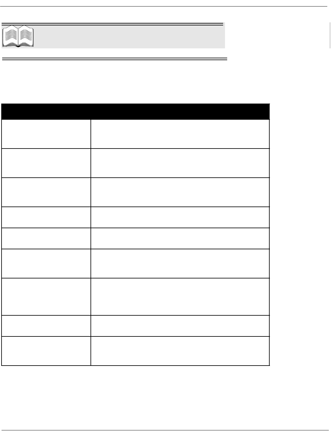
Table 1: Stakeholders and the communication needs served by architecture
Stakeholder Use
Architect and require-
ments engineers who rep-
resent the customer(s)
A forum for negotiating and making trade-offs among
competing requirements.
Architect and designers of
the constituent parts
To resolve resource contention and establish perfor-
mance and other kinds of run-time resource consumption
budgets.
Implementors To provide “marching orders,” inviolable constraints (plus
exploitable freedoms) on downstream development
activities.
Testers and integrators To specify the correct black-box behavior of the pieces
that must fit together.
Maintainers A starting point for maintenance activities, revealing the
areas a prospective change will affect.
Designers of other sys-
tems with which this one
must interoperate
To define the set of operations provided and required,
and the protocols for their operation.
Managers Basis for forming development teams corresponding to
the work assignments identified, work breakdown struc-
ture, planning, allocation of project resources, and track-
ing of progress by the various teams.
Product line managers To determine whether a potential new member of a prod-
uct family is in or out of scope, and if out, by how much.
Quality assurance team Basis for conformance checking, for assurance that
implementations have in fact been faithful to the architec-
tural prescriptions.

Documenting Software Architectures Clements, Bachmann, Bass, Garlan, Ivers, LIttle, Nord, Stafford
Copyright 2001 Addison Wesley, all rights reserved 18 Draft for review: Do not circulate without permission
Even if the future architect is the same person, he or she will use the documentation as a repository of thought,
a storehouse of detailed design decisions too numerous and hopelessly intertwined to ever be reproducible
from memory alone.
“”
“In our organization, a development group writes design documents to commu-
nicate with other developers, external test organizations, performance analysts,
the technical writers of manuals and product helps, the separate installation
package developers, the usability team, and the people who manage translation
testing for internationalization. Each of these groups has specific questions in
mind that are very different from the ones that other groups ask:
• What test cases will be needed to flush out functional errors?
• Where is this design likely to break down?
• Can the design be made easier to test?
• How will this design affect the response of the system to heavy loads?
• Are there aspects of this design that will affect its performance or ability to
scale to many users?
• What information will users or administrators need to use this system, and
can I imagine writing it from the information in this design?
• Does this design require users to answer configuration questions that they
won't know how to answer?
• Does it create restrictions that users will find onerous?
• How much translatable text will this design require?
• Does the design account for the problems of dealing with double-byte
character sets or bi-directional presentation? “
-- Kathryn Heninger Britton, IBM
|| END SIDEBAR/CALLOUT (Britton quote)
3. Architecture serves as the basis for system analysis. To support analysis, the architecture documenta-
tion must contain the information necessary for the particular analyses being performed. For example:
• For performance engineers, architecture provides the formal model that drives analytical tools such as
rate-monotonic real-time schedulability analysis, simulations and simulation generators, even theorem
provers and model checking verifiers. These tools require information about resource consumption,
scheduling policies, dependencies, and so forth.
• For those interested in the ability of the design to meet the system’s other quality objectives, the
architecture serves as the fodder for architectural evaluation methods. The architecture must contain
the information necessary to evaluate a variety of attributes such as security, performance, usability,
availability and modifiability. Analyses for each one of these attributes have their own information needs
and all of this information must be in the architecture.

Copyright 2001 Addison Wesley, all rights reserved 19 Draft for review: Do not circulate without permission
For more information...
Chapter 9 ("Choosing the Views") will employ the uses expected of the documentation,
and the documentation obligations each one imparts, as the basis for helping an architect
plan the documentation package.
The sidebar on the Architecture Tradeoff Analysis Method (ATAM) on page 239 contains
more information about a particular architecture evaluation approach and the documen-
tation needed to support it.
Coming to Terms
“Software Architecture”
If we are to agree what it means to document a software architecture, we should establish a common ba-
sis for what it is we’re documenting. While there is no universal definition of software architecture, there
is no shortage of them, either. The Software Engineering Institute’s web site collects definitions from the
literature and from practitioners; at the time this book was published, the collection numbered over 90.
The following are a few of the most-cited ones from published literature:
Definition
By analogy to building architecture, we propose the following model of software ar-
chitecture: Software Architecture = {Elements, Form, Rationale} That is, a software
architecture is a set of architectural (or, if you will, design) elements that have a
particular form. We distinguish three different classes of architectural elements:
processing elements; data elements; and connecting elements. The processing el-
ements are those components that supply the transformation on the data ele-
ments; the data elements are those that contain the information that is used and
transformed; the connecting elements (which at times may be either processing or
data elements, or both) are the glue that holds the different pieces of the architec-
ture together. For example, procedure calls, shared data, and messages are differ-
ent examples of connecting elements that serve to ``glue'' architectural elements
together. [D.E. Perry and A.L. Wolf, “Foundations for the Study of Software Archi-
tecture”, Software Engineering Notes, vol. 17, no. 4, Oct. 1992, pp. 40--52.]
Definition
Garlan and Shaw, 1993: ...beyond the algorithms and data structures of the compu-
tation; designing and specifying the overall system structure emerges as a new
kind of problem. Structural issues include gross organization and global control
structure; protocols for communication, synchronization, and data access; assign-
ment of functionality to design elements; physical distribution; composition of de-

Documenting Software Architectures Clements, Bachmann, Bass, Garlan, Ivers, LIttle, Nord, Stafford
Copyright 2001 Addison Wesley, all rights reserved 20 Draft for review: Do not circulate without permission
sign elements; scaling and performance; and selection among design alternatives.
[GS93]
Definition
Garlan and Perry, 1995: The structure of the components of a program/system,
their interrelationships, and principles and guidelines governing their design and
evolution over time. [GP95]
Definition
Bass, Clements, and Kazman, 1998: The software architecture of a program or com-
puting system is the structure or structures of the system, which comprise soft-
ware components, the externally visible properties of those components, and the
relationships among them. By “externally visible properties”, we are referring to
those assumptions other components can make of a component, such as its pro-
vided services, performance characteristics, fault handling, shared resource us-
age, and so on. [Bass 98]
Definition
Booch, Rumbaugh, and Jacobson, 1999: An architecture is the set of significant de-
cisions about the organization of a software system, the selection of the structural
elements and their interfaces by which the system is composed, together with their
behavior as specified in the collaborations among those elements, the composition
of these structural and behavioral elements into progressively larger subsystems,
and the architectural style that guides this organization---these elements and their
interfaces, their collaborations, and their composition (The UML Modeling Lan-
guage User Guide, Addison-Wesley, 1999)
Definition
IEEE, 2000:The fundamental organization of a system embodied in its components,
their relationships to each other, and to the environment, and the principles guid-
ing its design and evolution. [IEEE00] [IEEE Recommended Practice for Architec-
tural Description of Software-Intensive Systems, IEEE Std 1471-2000]
These definitions, and others like them, take a largely structural perspective on software architecture.
They hold that software architecture is composed of elements, connections among them, plus (usually)
some other aspect or aspects, such as configuration or style, constraints or semantics, analyses or prop-
erties, or rationale, requirements, or stakeholders' needs. Mary Shaw has observed that there seem to be
three additional main perspectives on architecture beyond the structural. Framework models are similar
to the structural perspective, but their primary emphasis is on the (usually singular) coherent structure of
the whole system, as opposed to concentrating on its composition. The framework perspective concen-
trates on domain-specific software architectures or domain-specific repositories, and often elevates mid-
dleware or communication infrastructures to a distinguished role. Dynamic models emphasize the

Copyright 2001 Addison Wesley, all rights reserved 21 Draft for review: Do not circulate without permission
behavioral quality of systems. “Dynamic” might refer to changes in the overall system configuration, set-
ting up or disabling pre-enabled communication or interaction pathways, or the dynamics involved in the
progress of the computation, such as changing data values. Finally, process models focus on construction
of the architecture, and the steps or process involved in that construction. From this perspective, archi-
tecture is the result of following a process script.
These perspectives do not preclude each other, nor do they really represent a fundamental conflict about
what software architecture is. Instead, they represent a spectrum in the software architecture community
about the emphasis that should be placed on architecture -- its constituent parts, the whole entity, the way
it behaves once built, or the building of it. Taken together, they form a consensus view of software archi-
tecture and help us make sense of the concept.
|| END SIDEBAR/CALLOUT on “Software Architecture”
Coming to Terms
“Documentation”
“Representation”
“Description”
“Specification”
What shall we call the activity of writing down a software architecture for the benefit of others (or for our
own benefit at a later time)? Leading contenders are documentation, representation, description, and
specification. For the most part we use “documentation” throughout this book, and we want to spend a
minute or two explaining why we.
Specification tends to connote an architecture rendered in some formal language. Now, we are all for for-
mal specs. (We have to be. One of us -- Ivers -- counts himself as a formalist, and he intimidates the rest
of us. In an early draft one of us called data flow diagrams a formal notation, and he just about gave him-
self an aneurysm. We recanted.) But the fact is that formal specs are not always practical nor are they
always necessary. Sometimes they aren’t even useful: How, for example, do you capture the rationale be-
hind your architectural decisions in a formal language?
Representation connotes a model, an abstraction, a rendition of a thing that is separate or different from
the thing itself. Is architecture something more than what someone writes down about it? Arguably yes,
but it’s certainly pretty intangible in any case. We felt that raising the issue of a model versus the thing
being modeled would only raise needlessly diverting questions best left to those whose hobby (or calling)
is philosophy: Does an abstraction of a tree falling in a model of a forest make a representation of a
sound? Don’t ask me; I haven’t a clue. (Better yet, ask Ivers.)
Description has been staked out by the Architecture Description Language (ADL) community.
For more information...
ADLs are discussed in Section 4.8 ("Notations for C&C Styles"), the For Further Read-
ing section of Chapter 8 ("Documenting Behavior"), and in a sidebar in Chapter 13 ("Re-
lated Work").
Good external references include [tbd].
It’s mildly curious that the formalists snagged the least rigorous-sounding term of the bunch. (If you don’t
believe this, the next time you board a jet ask yourself if you hope its flight control software has been spec-

Documenting Software Architectures Clements, Bachmann, Bass, Garlan, Ivers, LIttle, Nord, Stafford
Copyright 2001 Addison Wesley, all rights reserved 22 Draft for review: Do not circulate without permission
ified to the implementors, or merely described.) One would think that the ADL purveyors’ ambitions for
their languages are not very great, but that is not the case. In any event, we did not want anyone to think
that writing down an architecture was tantamount to choosing an ADL and using that (although that is an
option), so we eschewed description.
That leaves documentation. Documentation connotes the creation of an artifact—namely, a document.
(Note to Luddites: “Document” does not have to be a stack of paper. Electronic files and web pages make
perfectly fine documents.) Thus, documenting a software architecture becomes a very concrete task of
producing a software architecture document. Viewing the activity as creating a tangible product has ad-
vantages. We can describe good architecture documents, and bad ones. We can use completeness cri-
teria to judge how much work is left in producing this artifact, and determining when the task is done.
Planning or tracking a project’s progress around the creation of artifacts (documents) is an excellent way
to manage. Making the architecture information available to its consumers and keeping it up to date re-
duces to a solved problem of configuration control. Documentation can be formal or not, as appropriate,
and may contain models or not, as appropriate. Documents may describe, or they may specify. Hence,
the term is nicely general.
Finally, there is a long software engineering tradition to go with the term: Documentation is the task that
you are supposed to do because it’s good for you, like eating broccoli. It’s what your software engineering
teachers taught you to do, your customers contracted you to do, your managers nagged you to do, and
what you always found a way not to do. So if documentation brings up too many pangs of professional
guilt, use any term you like that’s more palatable. The essence of the activity is writing down (and keeping
current) the results of architectural decisions so that the stakeholders of the architecture — people who
need to know what it is to do their job — have the information they need in an accessible, non-ambiguous
form.
-- PCC
|| END SIDEBAR/CALLOUT “documentation,” “representation,” “specification,” etc.
Observation
“What’s the difference between architecture and design?”
The question that is the title of this sidebar has nipped at the heels of the architecture community for years,
and it is often the first question from someone who is trying to understand the concept of architecture.
Fortunately, the answer is easy. Architecture is design, but not all design is architecture. That is, there are
many design decisions that are left unbound by the architecture, and are happily left to the discretion and
good judgment of downstream designers and implementors. The architecture establishes constraints on
downstream activities, and those activities must produce artifacts (finer-grained designs and code) that
are compliant with the architecture, but architecture does not define an implementation.
You may ask, “What decisions are non-architectural? That is, what decisions does the architecture leave
unbound and at the discretion of others?”
For this, we appeal to our definition of architecture cited in the Preface: “...the structure or structures of
the system, each of which comprise elements, the externally-visible behavior of those elements, and the
relationships among them.”
So if a property of an architectural element is not visible (discernible) to any other architectural element,
that element is not architectural. The selection of a data structure, along with the algorithms to manage
and access that data structure, is a typical example. If the architectural prescription for this element is that
it provides programs, invoked from other elements, that store and retrieve data, then whether we choose
a linked list, an array, a stack, or any other solution is immaterial to those other elements, as long as our
choice lets us meet the developmental, behavioral, and quality requirements levied upon us.
“But wait,” you protest. “You used the term architectural element--what’s that? Are there non-architectural
elements? If so, what’s the difference?”

Copyright 2001 Addison Wesley, all rights reserved 23 Draft for review: Do not circulate without permission
There may be non-architectural elements; these are elements whose existence is unknown except to
those who are outside some architectural context. For instance, a module may correspond to a work as-
signment for a development team, and (if the module is created under the doctrine of information-hiding)
it encapsulates some changeable aspect about the system. Modules are hierarchical entities; that is, a
complex module (work assignment) can be decomposed into smaller modules (smaller work assign-
ments). Each module has an interface, and an implementation. The interface to the parent is a subset of
the union of the interfaces of the children. Suppose you’re in charge of implementing Module M, and (as
far as the architect has stipulated) M has no submodules. Say you discover that M’s interface routines
could all be implemented quite straightforwardly if you also designed and implemented a common set of
services that they could all use. You assign a small sub-team to design and implement this... this... this
what? Well, it’s clearly a work assignment, and it clearly encapsulates a changeable secret (namely, the
algorithms and data structures used by the common services), so that makes it a module, a sub-module
of M. Let’s call it M2:
“I get it,” you say. “Since M2’s existence is not known outside of M, it is not an architectural module.”
It’s tempting to agree at this point and be done with this, but that’s not quite the right way to look at things.
In some layered architectures, the layers at the top are not allowed to use the layers at the bottom; in es-
sence, the bottom layers’ services are not known to the top layers. But we would never say that the bottom
layers of an architecture are non-architectural. The argument about “unknown outside of” appeals to a re-
lation different than the one present in a module structure. Modules are related to each other by the “con-
tains” relation, or “shares a secret with” relation. Whether a module’s services are known or unknown by
another module is a property of the “uses” relation, which is a different kind of animal.
“OK,” you say. “So is module M2 an architectural element or not?”
I would say not, but not because it’s “invisible” to the other modules outside its parent. I’m afraid you’re
not going to like the reason. It’s a non-architectural element because the architect said so--that is, he or
she didn’t make it part of the architecture.
“You’re joking,” you say. “That’s a completely arbitrary definition!”
Not really. The architect didn’t make it part of the architecture because its existence (or non-existence)
were not material to the overall goals of the architecture. He or she gave you the freedom to structure your
team (implementing M) as you saw fit.
The fact is, there is no scale or scope or measure or dividing line between what is architectural and what
is not. One person’s architecture may be another person’s implementation, and vice versa. Suppose M2
turns out to be very complicated, and the sub-team you assign to it starts out by giving it an internal struc-
ture. To the coders of M2, that structure is an architecture. But to the architecture of the system that in-
cludes M, the very existence of M2 (let alone its internal structure) is just an implementation detail.
Modules and other hierarchical elements
1
are particularly prone to confusion about where to draw the line
between architecture and non-architectural design. If you want to be tediously precise about the matter,
the coding of each subroutine could be considered a separate work assignment, or even the coding of a
single line of code. Of course, we would not want to consider such minutiae to be architectural—the whole
point of architecture was to let us reason about larger issues. So when should an architect stop de-com-
1.
By “hierarchical element” we mean any kind of element that can consist of like-kind elements. A module is a hier-
archical element because modules consist of sub-modules, which are themselves modules. A task or process is
not.
M
M2
Key:
Notation: informal
-- module

Documenting Software Architectures Clements, Bachmann, Bass, Garlan, Ivers, LIttle, Nord, Stafford
Copyright 2001 Addison Wesley, all rights reserved 24 Draft for review: Do not circulate without permission
posing modules into smaller and smaller work assignments? One heuristic I know is due to David Parnas.
He says that a module is “small enough” when, in the face of a change, it would be just as easy to re-code
it as it would be to alter it. Now technically speaking, you can’t know a module’s code size at design time,
but if you can’t make a good guess then you’re probably not the right person to be the architect for the
system you’re working on anyway.
Processes and other non-hierarchical elements can also be non-architectural. Suppose the architect gave
you a CPU budget and the freedom to create up to 12 tasks, and suppose these tasks do not synchronize
or interact with any other tasks outside your work assignment. Then we could make the same argument
that these tasks (elements) are non-architectural.
“All right,” you sigh. “Once more, with clarity?”
Sure. Architecture is design, but not all design is architectural. The architect draws the boundary between
architectural and non-architectural design by making those decisions that need to be bound in order for
the system to meet its development, behavioral, and quality goals. (Decreeing what the modules are
achieves modifiability, for example.) All other decisions can be left to downstream designers and imple-
mentors. Decisions are architectural or not according to context. If structure is important to achieve your
system’s goals, then that structure is architectural. But designers of elements (or subsystems) that you
assign may have to introduce structure of their own to meet their goals, in which case such structures are
architectural—to them, but not to you.
Architecture is truly in the eye of the beholder. And what does all this have to do with documentation? If
your goals are met by an architecture, then document it as such but expect the possibility that subsequent
finer-grained design may produce architectural documentation (about a small piece of your system) on its
own.
-- PCC
|| END SIDEBAR/CALLOUT
Seven Rules for Sound Documentation
Architecture documentation is in many ways akin to the documentation we write in other facets of our software
development projects. As such, it obeys the same fundamental rules for what sets apart good, usable docu-
mentation from poor, ignored documentation. These rules for any software documentation, including software
architecture documentation, are summarized below:
Advice
1. Documentation should be written from the point of view of the reader, not the writer.
2. Avoid unnecessary repetition.
3. Avoid ambiguity.
4. Use a standard organization.
5. Record rationale.
6. Keep documentation current but not too current.
7. Review documentation for fitness of purpose
The following expands each of the seven rules.

Copyright 2001 Addison Wesley, all rights reserved 25 Draft for review: Do not circulate without permission
Advice
1. Documentation should be written from the point of view of the reader, not the writer.
Seemingly obvious but surprisingly seldom considered, this rule offers the following advantages:
• A document is written approximately once (a little more than that if you count the time for revisions) but
if useful it will be read many scores of times. Therefore, the document’s “efficiency” is optimized if we
make things easier for the reader. Edsger Dijkstra, the inventor of many of the software engineering
principles we now take for granted, once said that he will happily spend two hours pondering how to
make a single sentence clearer. He reasons that if the paper is read by a couple of hundred people —
a decidedly modest estimate for someone of Dijkstra’s caliber — and he can save each reader a minute
or two of confusion, then it’s well worth the effort. Professor Dijkstra’s consideration for the reader
reflects his classic old-world manners, which brings us to the second argument:
• Writing for the reader is just plain polite. A reader who feels like the document was written with him or
her in mind appreciates the effort, but more to the point, will come back to the document again and
again in the future. Which brings us to the third argument:
• Documents written for the reader will be read; documents written for the convenience of the writer will
not be. It’s the same reason we like to shop at stores that seem to want our business, and avoid stores
that do not.
In the realm of software documentation, documents written for the writer often take one of two forms: Stream
of consciousness or stream of execution. Stream of consciousness writing captures thoughts in the order in
which they occurred to the writer, and lack the organization helpful to a reader. Avoid stream of consciousness
writing by making sure that you know what question(s) are being answered by each section of a document.
Stream of execution writing captures thoughts in the order in which they occur during the execution of a soft-
ware program. For certain kinds of software documentation, this is entirely appropriate, but it should never be
given as the whole story.
Advice
2. Avoid unnecessary repetition.
Each kind of information should be recorded in exactly one place. This makes documentation easier to use and
much easier to change as it evolves. It also avoids confusion, because information that is repeated is often re-
peated in a slightly different form, and now the reader must wonder: Was the difference intentional? If so, what
is the meaning of the difference?
Now, expressing the same idea in different forms is often useful for achieving a thorough understanding. You
could make the case that the whole concept of architectural views — see "Views" on page 31 — flows from
exactly this concept. That section describes and gives some rationale for the need for multiple architectural
views of a system. However, it should be a goal that information never be repeated, or almost never repeated,
verbatim unless the cost to the reader of keeping related information separate is high. Locality of information

Documenting Software Architectures Clements, Bachmann, Bass, Garlan, Ivers, LIttle, Nord, Stafford
Copyright 2001 Addison Wesley, all rights reserved 26 Draft for review: Do not circulate without permission
reference is important; unnecessary page flipping leads to unsatisfied readers. Also, two different views might
have repetitive information for clarity or to make different points. If keeping the information separate proves too
high a cost to the reader, repeat the information.
Advice
3. Avoid ambiguity.
A primary reason architecture is useful is because it suppresses or defers the plethora of details that are nec-
essary to resolve before bringing a system to the field. The architecture is therefore ambiguous, one might ar-
gue, with respect to these suppressed details. Even though an architecture may be brought to fruition by any
of a number of different elaborations/implementations, as long as those implementations comply with the archi-
tecture, they are all correct. Unplanned ambiguity occurs when documentation can be interpreted in more than
one way, and at least one of those ways is incorrect. The documentation should be sufficient to avoid multiple
interpretations.
“”
“Clarity is our only defense against the embarrassment felt on completion of a
large project when it is discovered that the wrong problem has been solved.”
-- C. A. R. Hoare, “An Overview of Some Formal Methods for Program Design,”
IEEE Computer, September 1987, pp. 85-91.
A well-defined notation with precise semantics goes a long way toward eliminating whole classes of linguistic
ambiguity from a document. This is one area where architecture description languages help a great deal, but
using a formal language isn’t always necessary. Just adopting a set of notational conventions and then avoiding
unplanned repetition (especially the “almost-alike” repetition mentioned previously) will help eliminate whole
classes of ambiguity. But if you do adopt a notation, then this corollary applies:
Advice
3a. Explain your notation.
One of the greatest sources of ambiguity in architecture documentation are those ubiquitous box-and-line dia-
grams that people always draw on whiteboards or backs of napkins. While not a bad starting point, these dia-
grams are certainly not good architecture documentation. For one thing, the behavior of the elements is not
defined, and this (as we shall see) is a crucial part of the architecture. But beyond that, most of these diagrams
suffer from ambiguity. Are the boxes supposed to be modules, objects, classes, processes, functions, proce-
dures, processors, or something else? Do the arrows mean submodule, inheritance, synchronization, exclu-
sion, calls, uses, data flow, processor migration, or something else?
We have three things to say about box-and-line diagrams masquerading as architecture documentation:

Copyright 2001 Addison Wesley, all rights reserved 27 Draft for review: Do not circulate without permission
• Don’t be guilty of drawing one and claiming it’s anything more than a start at an architectural
description.
• If you draw one yourself, make sure you explain precisely what the boxes and lines mean.
• If you see one, ask its author what the boxes mean and what precisely the arrows connote. The result
is usually illuminating, even if the only thing illuminated is the owner’s confusion.
Make it as easy as possible for your reader to find out the meaning of the notation. If you’re using a standard
visual language defined elsewhere, refer readers to the source of the language’s semantics. (Even if the lan-
guage is very standard or widely-used, different versions often exist. Let your reader know, by citation, which
one you’re using.) If the notation is home-grown include a key to the symbology. This is good practice because
it compels you to understand what the pieces of your system are and how they relate to each other; and it is
also courteous to your readers.
Background
Quivering at Arrows
Many architectural diagrams employing an informal notation use arrows to indicate some form of direc-
tional relationship among architectural elements. While this might seem like a good and innocuous way
to clarify a design by adding additional visual semantic detail, it turns out in many cases to be a great
source of confusion.
The problem is that it is usually not clear what arrows mean. Do they indicate direction of data flow? Vis-
ibility of services or data? Control flow? Invocation? Any of these might make sense, and people use ar-
rows to mean all of these things and more, often using multiple interpretations in the same diagram.
Consider the architectural snippet in the figure below. Suppose that C
1
invokes C
2
via a simple procedure
call. What might the arrow mean? It might mean that C
1
calls C
2
. It might mean that C
1
passes data to C
2
via its parameters. It might mean that C
1
obtains a return result from C
2
. It might mean that C
1
causes C
2
to come into existence or be loaded into a memory space. It might mean that C
2
cannot execute until C
1
does. It might mean that C
1
cannot execute until C
2
terminates. All of these interpretations are valid under
the assumption that C
1
invokes C
2.
Alternatively, suppose we know that C
1
invokes C
2
and we want to show a data flow relation between the
two. We could use the figure above -- but if C
2
returns a value to C
1
, shouldn’t there be an arrow going
both ways? Or should there be a single arrow with two arrowheads? These two options are not inter-
changeable. A double-headed arrow typically denotes some symmetric relation between two elements,
whereas two single-headed arrows suggest two asymmetric relations at work. In either case, the diagram
will lose the information that it was C
1
which initiated the interaction. Suppose C
2
also invokes C
1
. Would
we need to put two double-headed arrows between C
1
and C
2
?
The same questions apply if we wanted to show control flow: How should we depict the fact that C
2
returns
control to C
1
after its execution has completed?
C
1
C
2
(add key)
Documenting Software Architectures Clements, Bachmann, Bass, Garlan, Ivers, LIttle, Nord, Stafford
Copyright 2001 Addison Wesley, all rights reserved 28 Draft for review: Do not circulate without permission
Of course, the situation is even worse if the relationship is a more complex form of interaction, possibly
involving multiple procedure calls, complex protocols, rules for handling exceptions and time-outs, and
callbacks.
To avoid confusion here are a few words of advice:
Advice
Explain what semantic and notational conventions you are using.
When arrows represent non-trivial interactions, document the behavior using some form of behavior (or
protocol) specification.
For more information...
Chapter 8 provides guidance about documenting behavior.
Advice
Use different visual conventions to distinguish between semantically-distinct
types of interaction within the same diagram.
For example, a dotted line might be used to indicate a control relationship, while a solid line represents a
data transfer relationship. Similarly, different arrowhead shapes can help make distinctions.
Advice
Use similar visual conventions for interactions that are similar.
For example, a procedure call-based interaction should use the same kind of connecting line throughout
the architectural documentation.
Advice
Don’t feel compelled to use arrows.
Often one can avoid confusion by not using arrows where they are likely to be misinterpreted. For exam-
ple, one can use lines without arrowheads. Sometimes physical placement, as in a layered diagram, can
convey the same information.
-- DG
|| END SIDEBAR/CALLOUT
Advice
4. Use a standard organization.

Copyright 2001 Addison Wesley, all rights reserved 29 Draft for review: Do not circulate without permission
Establish a standard, planned organization scheme, make your documents adhere to it, and ensure that read-
ers know about it. A standard organization offers many benefits:
• It helps the reader navigate the document and find specific information quickly (and so this is also
related to the write-for-the-reader rule).
• It also helps the writer of the document. It helps plan and organize the contents, and it reveals instantly
what work remains to be done by the number of sections that still contain “TBD” marks.
• It embodies completeness rules for the information; the sections of the document constitute the set of
important aspects that need to be conveyed. Hence, the standard organization can form the basis for
a first-order validation check of the document at review time.
Corollaries include:
Advice
4a. Organize documentation for ease of reference.
Software documentation may be read from cover to cover at most once, and probably never. But a document
is likely to be referenced hundreds or thousands of times.
Advice
4b. Mark what you don’t yet know with “to be determined” rather than leaving it blank.
Many times we can’t fill in a document completely because we don’t yet know the information or because de-
cisions have not been made. In that case, mark the document accordingly, rather than leaving the section blank.
If blank, the reader will wonder whether the information is coming, or whether a mistake was made.
For more information...
Chapter 10 ("Building the Documentation Package") contains a standard organization
that we recommend for documenting views, and for documenting information that ap-
plies across views. Chapter 11 ("Documenting Software Interfaces") contains a standard
organization for the documentation of a software interface.
Advice
5. Record rationale.
When you document the results of decisions, record the alternatives you rejected and say why. Next year (or
next week) when those decisions come under scrutiny or pressure to change, you will find yourself re-visiting

Documenting Software Architectures Clements, Bachmann, Bass, Garlan, Ivers, LIttle, Nord, Stafford
Copyright 2001 Addison Wesley, all rights reserved 30 Draft for review: Do not circulate without permission
the same arguments and wondering why you didn’t take some other path. Recording rationale will save you
enormous time in the long run, although it requires discipline to record in the heat of the moment.
Advice
6. Keep documentation current but not too current.
Documentation that is incomplete, out of date, does not reflect truth, and does not obey its own rules for form
and internal consistency is not used. Documentation that is kept current and accurate is used. Why? Because,
questions about the software can be most easily and most efficiently answered by referring to the appropriate
document. If the documentation is somehow inadequate to answer the question, then it needs to be fixed. Up-
dating it and then referring the questioner to it will deliver a strong message that the documentation is the final
authoritative source for information.
During the design process, on the other hand, decisions are made and reconsidered with great frequency. Re-
vising documentation to reflect decisions that will not persist is an unnecessary expense.
Your development plan should specify particular points at which the documentation is brought up to date or the
process for keeping the documentation current. Every design decision should not be recorded the instant it is
made but rather that the document is subject to version control and has a release strategy just as every other
artifact being produced during a development.
For more information...
"Documentation across views" on page 249 discusses the documentation of rationale.
Advice
7. Review documentation for fitness of purpose.
Only the intended users of a document will be able to tell you if it contains the right information presented in the
right way. Enlist their aid. Before a document is released, have it reviewed by representatives of the community
or communities for whom it was written.
For more information...
Chapter 12 ("Reviewing Software Architecture Documentation") will show how to re-
view software architecture documentation to make sure it is of high quality and utility
and that it conforms to these rules, among other things.

Copyright 2001 Addison Wesley, all rights reserved 31 Draft for review: Do not circulate without permission
Views
Perhaps the most important concept associated with software architecture documentation is that of the view. A
software architecture is a complex entity that cannot be described in a simple one-dimensional fashion. The
analogy with building architecture, if not taken too far, proves illuminating. There is no single rendition of a build-
ing architecture. Instead, there are many: The room layouts, the elevation drawings, the electrical diagrams,
the plumbing diagrams, the ventilation diagrams, the traffic patterns, the sunlight and passive solar views, the
security system plans, and many others. Which of these views is the architecture? None of them. Which views
convey the architecture? All of them.
Coming to Terms
“Architectural views”
As long ago as 1974, Parnas observed that software comprises many structures, which he defined as par-
tial descriptions of a system showing it as a collection of parts and showing some relations between the
parts [P74]. This definition largely survives in architecture papers today. Parnas identified several struc-
tures prevalent in software. A few were fairly specific to operating systems (such as the structure that de-
fines what process owns what memory segment) but others are more generic and broadly applicable.
These include the module structure (the units are work assignments, the relation is “is a part of” or “shares
part of the same secret as”), the uses structure (the units are programs, and the relation is “depends on
the correctness of”), and the process structure (the units are processes, and the relation is “gives compu-
tational work to”).
More recently, Philippe Kruchten of the Rational Corporation wrote a very influential paper describing four
main views of software architecture that can be used to great advantage in system-building, plus a distin-
guished fifth view that ties the other four together—the so-called “4+1” approach to architecture. [K95],
which comprises the following:
•The logical view primarily supports behavioral requirements--the services the system should provide to
its end users. Designers decompose the system into a set of key abstractions, taken mainly from the
problem domain. These abstractions are objects or object classes that exploit the principles of abstrac-
tion, encapsulation, and inheritance. In addition to aiding functional analysis, decomposition identifies
mechanisms and design elements that are common across the system.
•The process view addresses concurrency and distribution, system integrity, and fault-tolerance. The
process view also specifies which thread of control executes each operation of each class identified in
the logical view. The process view can be seen as a set of independently executing logical networks of
communicating programs (“processes”) that are distributed across a set of hardware resources, which
in turn are connected by a bus or local area network or wide area network.
•The development view focuses on the organization of the actual software modules in the software-de-
velopment environment. The units of this view are small chunks of software—program libraries or sub-
systems—that can be developed by one or more developers. The development view supports the
allocation of requirements and work to teams, and supports cost evaluation, planning, monitoring of
project progress, and reasoning about software reuse, portability, and security.
•The physical view takes into account the system's requirements such as system availability, reliability
(fault-tolerance), performance (throughput), and scalability. This view maps the various elements iden-
tified in the logical, process, and development views—networks, processes, tasks, and objects—onto
the processing nodes.
Finally, Kruchten prescribes using a small subset of important scenarios—instances of use cases—to
show that the elements of the four views work together seamlessly. This is the “plus one” view, redundant

Documenting Software Architectures Clements, Bachmann, Bass, Garlan, Ivers, LIttle, Nord, Stafford
Copyright 2001 Addison Wesley, all rights reserved 32 Draft for review: Do not circulate without permission
with the others but serving a distinct purpose. The 4+1 approach has since been embraced as a founda-
tion piece of Rational’s Unified Process [ref].
For more information...
To see how the 4+1 views correspond to views described in this book, see "Rational Uni-
fied Process / Kruchten 4+1" on page 311.
At about the same time, Dilip Soni, Robert Nord, and Christine Hofmeister of Siemens Corporate Re-
search made a similar observation about views of architecture they observed in use in industrial practice
[SNH95]. They wrote:
• The conceptual view describes the system in terms of its major design elements and the relationships
among them.
• The module interconnection view encompasses two orthogonal structures: functional decomposition
and layers.
• The execution view describes the dynamic structure of a system.
• The code view describes how the source code, binaries, and libraries are organized in the development
environment.
These have now become known as the Siemens Four View model for architecture [ASA].
For more information...
To see how the Siemens Four View model corresponds to the views described in this
book, see "Siemens Four Views" on page 314.
Other “view sets” are emerging. In their 1999 book Business Component Factory, Peter Herzum and Ol-
iver Sims prescribe these four as the most important for their business component factory approach:
• The technical architecture, concerned with the component execution environment, the set of tools, the
user interface framework, and any other technical services/facilities required to develop and run a com-
ponent-based system.
• The application architecture, concerned with the set of architectural decisions, patterns, guidelines, and
standards requires to build a component-based system.
• The project management architecture, comprising those elements needed to build a scalable large sys-
tem with a large team. It includes the concepts, guidelines, principles, and management tools needed
to carry out industrial-scale development.
• The functional architecture, where the specification and implementation of the system reside.
Like electrical and plumbing diagrams, each view of a software architecture is used for a different purpose,
and often by different stakeholders. As such, they form the basic unit for documenting a software archi-
tecture.
|| END SIDEBAR/CALLOUT on Views
For our purposes, we define a view as follows:
Definition
A view is a representation of a set of system elements and relationships among
them.

Copyright 2001 Addison Wesley, all rights reserved 33 Draft for review: Do not circulate without permission
We use the concept of views to give us the most fundamental principle of architecture documentation, illustrated
in Figure 3:
What are the relevant views? It depends on your goals. As we saw previously, architecture documentation can
serve many purposes: a mission statement for implementors, a basis for analysis, the specification for auto-
matic code generation, the starting point for system understanding and asset recovery, or the blueprint for
project planning.
Different views also expose different quality attributes to different degrees. Therefore, the quality attributes that
are of most concern to you and the other stakeholders in the system’s development will affect the choice of what
views to document. For instance, a layered view will tell you about your system’s portability. A deployment view
will let you reason about your system’s performance and reliability. And so forth.
For more information...
Layered views are covered in Chapter 2 ("Styles of the Module Viewtype"). Chapter 6
("Styles of the Allocation Viewtype") covers the deployment view. Chapter 9 ("Choosing
the Views") prescribes how to select the set of relevant architectural views for a particular
system.
Different views support different goals and uses. This is fundamentally why we do not advocate a particular view
or collection of views. The views you should document depend on the uses you expect to make of the docu-
mentation. Different views will highlight different system elements and/or relationships.
Figure 3: A documentation package for a software architecture is composed of several parts. The main part of the
package consists of one or more view documents. The remainder consists of documentation that explains how the
views relate to each other, introduces the package to its readers, and guides them through it.
Section n: View
Software
Architecture
S
o
f
t
w
a
r
e
A
r
c
h
i
t
e
c
t
u
r
e
f
o
r
S
y
s
t
e
m
X
Y
Z
Section 1: View
. . .
Section 2: View
=
Section n+1:
Documentation
D
o
c
’
n
A
c
r
o
s
s
V
i
e
w
s
Across Views
+
Documenting an architecture is a matter of documenting the relevant views, and
then adding documentation that applies to more than one view.

Documenting Software Architectures Clements, Bachmann, Bass, Garlan, Ivers, LIttle, Nord, Stafford
Copyright 2001 Addison Wesley, all rights reserved 34 Draft for review: Do not circulate without permission
“”
“Many projects make the mistake of trying to impose a single partition in multiple
component domains, such as equating threads with objects, which are equated
with modules, which in turn are equated with files. Such an approach never suc-
ceeds fully, and adjustments eventually must be made, but the damage of the ini-
tial intent is often hard to repair. This invariably leads to problems in development
and occasionally in final products. We have collected several real-life reports of
such developments.”
-- Alexander Ran in Software Architecture for Product Families, by Jazayeri, Ran,
and van der Linden. Addison Wesley Longman 2000.
It may be disconcerting that no single view can fully represent an architecture. Additionally, it feels somehow
inadequate to see the system only through discrete, multiple views that may or may not relate to each other in
any straightforward way. It makes us feel like the blind men groping the elephant. The essence of architecture
is the suppression of information not necessary to the task at hand, and so it is somehow fitting that the very
nature of architecture is such that it never presents its whole self to us, but only a facet or two at a time. The is
its strength: each view emphasize certain aspects of the system while de-emphasizing or ignoring other as-
pects, all in the interest of making the problem at hand tractable. Nevertheless, no one of these individual views
adequately documents the software architecture for the system. That is accomplished by the complete set of
views along with information that transcends them.
“”
“An object-oriented program’s runtime structure often bears little resemblance to
its code structure. The code structure is frozen at compile-time; it consists of
classes in fixed inheritance relationships. A program’s runtime structure consists
of rapidly changing networks of communicating objects. In fact, the two struc-
tures are largely independent. Trying to understand one from the other is like try-
ing to understand the dynamism of living ecosystems from the static taxonomy
of plants and animals, and vice versa.” [GHJV95]
What does the documentation for a view contain? Briefly it contains
• a primary presentation (usually graphical) that depicts the primary elements and relations of the view
• an element catalog that explains and defines the elements shown in the view and gives their properties
• a specification of the elements’ interfaces and their behavior
• a variability guide explaining any built-in mechanisms available for tailoring the architecture
• rationale and design information
For more information...
Section 10.1 ("Documenting a view") prescribes the contents of a view document in de-
tail. Chapters following in Part I introduce specific views and the uses for each. Chapter
11 ("Documenting Software Interfaces") prescribes the contents of an element’s interface
documentation.

Copyright 2001 Addison Wesley, all rights reserved 35 Draft for review: Do not circulate without permission
What is the documentation that applies across views? Briefly it contains
• an introduction to the entire package, including a reader’s guide that helps a stakeholder find a desired
piece of information quickly
• information describing how the views relate to each other, and to the system as a whole
• constraints and rationale for the overall architecture
• such management information as may be required to effectively maintain the whole package
For more information...
Section 10.2 ("Documentation across views") prescribes the contents of the cross-view
documentation in detail.
Viewtypes and Styles
Viewtypes
While there is not a fixed set of views appropriate for every system, there are broad guidelines that help us gain
a footing. In general, architects need to think about their software three different ways at once:
1. How it is structured as a set of implementation units
2. How it is structured as a set of elements that have run-time behavior and interactions
3. How it relates to non-software structures in its environment
Each view we present in Part I falls into one of these three categories, which we call viewtypes. The three view-
types are
1. the module viewtype
2. the component-and-connector (C&C) viewtype, and
3. the allocation viewtype.
Views in the module viewtype (module views for short) document a system’s principal units of implementation.
Views in the C&C viewtype (C&C views) document the system’s units of execution. And views in the allocation
viewtype (allocation views) document the relationships between a system’s software and its development and
execution environments. A viewtype constrains the set of elements and relations that exist in its views.
Definition
A viewtype defines the element types and relation types used to describe the archi-
tecture of a software system from a particular perspective.

Documenting Software Architectures Clements, Bachmann, Bass, Garlan, Ivers, LIttle, Nord, Stafford
Copyright 2001 Addison Wesley, all rights reserved 36 Draft for review: Do not circulate without permission
Styles
Within the confines of a viewtype, recurring forms have been widely observed, even if written for completely
different systems. These forms occur often enough that they are worth writing and learning about in their own
right. Perhaps they have interesting properties not shared by others. Perhaps they represent a significant and
oft-used variation of the viewtype. Our description of each viewtype includes a section on commonly-occurring
forms and variations. We call these architectural styles, or styles for short. Styles have implications for archi-
tectural documentation and they deserve definition and discussion in their own right.
Definition
An architectural style is a specialization of elements and relationships, together
with a set of constraints on how they can be used.
A style defines a family of architectures that satisfy the constraints. A style is typically described as a set of
element and relation types, together with a set of constraints on how they can be used. Styles allow one to apply
specialized design knowledge to a particular class of systems and to support that class of system design with
style-specific tools, analysis, and implementations. The literature is replete with a number of styles, and most
architects have a wide selection in their repertoire.
For example, we’ll see that modules can be arranged into a very useful configuration by restricting what each
one is allowed to use. The result is a layered style (a member of the module viewtype) that imparts to systems
that employ it qualities of modifiability, portability, and the ability to quickly extract a useful subset. Different sys-
tems will have a different number of layers, different contents in each layer, and different rules for what each
layer is allowed to use. However, the layered style is abstract with respect to these options, and can be studied
and analyzed without binding them.
For another example, we’ll see that client-server is a common architectural style (a member of the component-
and-connector viewtype). The elements in this style are clients, servers, and the protocol connectors that depict
their interaction. When employed in a system, the client-server style imparts desirable properties to the system,
such as the ability to add new clients with very little effort. Different systems will have a different protocols, dif-
ferent numbers of servers, and different numbers of clients each can support. However, the client-server style
is abstract with respect to these options, and can be studied and analyzed without binding them.
Some styles occur in every software system. Decomposition, uses, deployment, and work assignment styles
are examples of these. Other styles occur only in systems where they were explicitly chosen and designed in
by the architect. Layered, communicating process, and client-server are examples of “chosen” styles.
Choosing a style for your system, whether covered in this book or somewhere else, imparts a documentation
obligation to record the specializations and constraints that the style imposes and the properties that the style
imparts to the system. We call this piece of documentation a style guide. The obligation to document a style
can usually be discharged by citing a description of the style in the literature (this book, for example). If you
invent your own style, however, you will need to write a style guide for it.

Copyright 2001 Addison Wesley, all rights reserved 37 Draft for review: Do not circulate without permission
For more information...
Chapter 2 ("Styles of the Module Viewtype"), Chapter 4 ("Styles of the C&C Viewtype"),
and Chapter 6 ("Styles of the Allocation Viewtype") present the styles we cover in this
book, one per section. Each of those sections serves as an example of a style guide.
Section 7.5 ("Creating and Documenting a New Style") explains how to devise, and doc-
ument, a style of your own.
Books that catalog architectural styles include... [tbd]
No system is built exclusively from a single style. On the contrary, every system can be seen to be an amal-
gamation of many different styles. This amalgamation includes the styles we mentioned above that occur in
every system, but systems usually also exhibit a combination of the so-called “chosen” styles as well. This
amalgamation can occur in three ways:
• Different “areas” of the system might exhibit different styles. For example, a system might employ a
pipe-and-filter style to process input data, but the result is then routed to a database that is accessed
by many elements. This system would be a blend of a pipe-and-filter and shared-data styles.
Documentation for this system would include a pipe-and-filter view that showed one part of the system,
and a shared-data view that showed the other part.
In a case like this, one or more elements must occur in both views and have properties of both kinds
of elements. (Otherwise, the two parts of the system could not communicate with each other.) These
“bridging elements” provide the continuity of understanding from one view to the next. They likely have
multiple interfaces, each providing the mechanisms for letting the element work with other elements in
each of the views to which it belongs.
• An element playing a part in one style may itself be composed of elements arranged in another style.
For example, a server in a client-server system might (unknown to the other servers or its own clients)
be implemented using a pipe-and-filter style. Documentation for this system would include a client-
server view showing the overall system, as well as a pipe-and-filter view documenting that server.
• Finally, the same system may simply be seen in different lights, as though you were looking at it through
filtered glasses. A system featuring a database repository may be seen as embodying either a shared-
data style or a client-server style. If the clients are independent processes, then the system may be
seen embodying a communicating process style. The glasses you choose will determine the style that
you “see.”
In the last case, the choice of style-filtered glasses that you make depends (once again) on the uses to which
you and your stakeholders intend to put the documentation. For instance, if the shared-data style gives you all
the analysis tools you need, you might choose it in lieu of the other two options. If you need the perspective
afforded by more than one style, however, then you have a choice. You can document the corresponding views
separately, or you can combine them into a single view that is (roughly speaking) the union of what the separate
views would be.
For more information...
Combining views is an important concept which is covered in Section 7.3.

Documenting Software Architectures Clements, Bachmann, Bass, Garlan, Ivers, LIttle, Nord, Stafford
Copyright 2001 Addison Wesley, all rights reserved 38 Draft for review: Do not circulate without permission
All three cases make it clear for the need to be able to document different parts of a system using different
views. That is, a view need not show the entire system.
Summary: Viewtypes, Styles, and Views
The three viewtypes -- module, c&c, and allocation -- represent the three perspectives that an architect must
consider when designing a system: the system as units of implementation, the system as units of run -time ex-
ecution, and the mapping from software elements to environmental structures. A viewtype restricts the element
types (modules in the module viewtype, for instance) and the corresponding relationship types.
But even within the confines of a viewtype, there are still choices to be made: How the elements are restricted,
how they relate to each other, and constraints on their use or configuration. A style is a specialization of a view-
type that reflects recurring patterns of interaction, independent of any particular system.
And even within the confines of a style, there are still choices to be made: How the elements and relations in a
style are bound to actual elements and relations in a system. In the context of viewtypes and styles, then, a
view can now be seen as a style that is bound to a particular system. For example, Section 4.4 describes the
publish-subscribe style in terms of loosely-coupled components whose interfaces allow the reporting of events
and subscription to events, but the description of the style in Section 4.4 is independent of any system. If you
choose the publish-subscribe as a design strategy for your system, then you will produce a publish-subscribe
view by naming the actual components, and the events they report and to which they subscribe.
Background
Style Guides
Chapter 1 through Chapter 6 introduce the three viewtypes, and several prominent styles of each. All of the
viewtype and style descriptions in those chapters follow the same outline, which constitutes the standard orga-
nization of a style guide:
1. Overview. The overview explains why this viewtype/style is useful for documenting a software architecture.
It discusses what it is about a system that the viewtype/style addresses, and how it supports reasoning
about and analysis of systems.
2. Elements, Relations, and Properties.
a. Elements are the architectural building blocks native to the viewtype/style. The description of elements
tells what role they play in an architecture and furnishes guidelines for effective documentation of the
elements in views.
b. Relations determine the how the elements work together to accomplish the work of the system. The
discussion names the relations among elements, and provides rules on how elements can and cannot
be related.
c. Properties are additional information about the elements and their associated relations. When an
architect documents a view, the properties will be given values. For example, properties of a layer (an
element of the layers style, which is in the module viewtype) include the layer’s name, the units of
software the layer contains, and the nature of the virtual machine that the layer provides. A layers view
will, for each layer, specify its name, the unit of software it contains, and the virtual machine it provides.

Copyright 2001 Addison Wesley, all rights reserved 39 Draft for review: Do not circulate without permission
Thus, the existence of a property in a viewtype/style imparts an obligation on the architect, when
documenting a corresponding view, to fill in that property.
In addition, the architect is free to specify additional properties in a view that do not correspond to
properties we named in the viewtype/style.
3. What it’s for and not for. This describes what kind of reasoning is supported and, just as important, what
kind of reasoning is not supported by views in the viewtype or style. It describes typical users and their
utilization of the resulting views. Its purpose is to help the architect understand to what purpose(s) a view
in this viewtype or style may be put.
4. Notations. Descriptions are given of graphical and/or textual representations that are available to document
views in the viewtype/style. Different notations will also support the conveyance of different kinds of infor-
mation in the primary presentation.
5. Relations to other views. This section will describe how views in the viewtype/style may be related to those
in different viewtypes, or even in different styles in the same viewtype. For example, views in two different
styles might convey slightly different but related information about a system, and the architect will need a
way to choose which one to employ. This section might also include warnings about other views with which
a particular view is often confused, to the detriment of the system and its stakeholders. Finally, this section
might include a suggestion about useful mappings that can be built by combining a view in this viewtype
with another.
|| END SIDEBAR/CALLOUT on style guides
Coming to Terms
“Module”
“Component”
For the purposes of documenting software architectures, we have in this book divided the universe into
three parts: a module viewtype, a component-and-connector viewtype, and an allocation viewtype. This
three-way distinction allows us to structure the information we’re presenting in an orderly way, and (we
hope) allows you to recall it and access it in an orderly way. But for this to succeed, the distinctions have
to be meaningful. Two of the categories rely on words that, it must be admitted, are not historically well-
differentiated: component and module.
Like many words in computing, these two have meanings outside our field. A component is “a constituent
element, as of a system” [ref: The American Heritage Dictionary, 2nd college edition, Houghton Mifflin Co.,
Boston, 1991]. Think stereo or home entertainment system components. A module is “a standardized unit
constructed for use with others of its kind” [ibid]
2
.
2.
Other fields co-opted the word “module” before ours did. It also has meaning in
- building architecture, as “a uniform structural component used repeatedly in a building,”
- electronics, as “a self-contained assembly of electronic components and circuitry, such as a stage in a computer,”
- spacecraft design, as “a self-contained unit of a spacecraft that performs a specific task or class of tasks in support
of the major function of the craft” (remember the Command and Service Modules from the Apollo program?), and
- educational design, as “a unit of instruction that covers a single topic or a small section of a broad topic.”

Documenting Software Architectures Clements, Bachmann, Bass, Garlan, Ivers, LIttle, Nord, Stafford
Copyright 2001 Addison Wesley, all rights reserved 40 Draft for review: Do not circulate without permission
Clear on the difference? No? Well, same here. To complicate matters, both terms have come to be asso-
ciated with movements in software engineering that share a great deal of overlap in their goals.
Modules led the way. During the 1960’s and 70’s as software systems increased in size and were no long-
er able to be produced by one person, it became clear that new techniques were needed to manage soft-
ware complexity and to partition work among programmers. To address such issues of “programming in
the large” various criteria were introduced to help programmers decide how to partition their software. En-
capsulation, information hiding, and abstract data types became the dominant design paradigms of the
day, and they used module as the carrier of their meaning. The 1970’s and 1980’s saw the advent of “mod-
ule interconnection languages” and features of new programming languages such as Modula modules,
Smalltalk classes, and Ada packages. Today’s dominant design paradigm, object oriented programming,
has these module concepts at its heart.
Components are currently in the limelight with component-based software engineering and the compo-
nent-and-connector perspective in the software architecture field.
These movements both aspire to achieve rapid system construction and evolution through the selection,
assembly, and wholesale replacement of independent sub-pieces. What Eli Whitney and interchangeable
parts did for rifles around 1810, modules and components aim to do for software. Both terms are about
the decomposition of a whole software system into constituent parts, but beyond that they take on different
shades of meaning:
• A module tends to refer first and foremost to a design-time entity. Parnas’s foundational work in module
design used information-hiding as the criterion for allocating responsibility to a module. Information that
was likely to change over the lifetime of a system, such as the choice of data structures or algorithms,
was assigned to a module, which had an interface through which its facilities were accessed.
• A component tends to refer to a run-time entity. Shaw and Garlan, for example, speak of an architecture
of a system as a collection of “computational components -- or simply components” along with a de-
scription of their interactions [SG, p.20]. Szyperski says that a component “can be deployed indepen-
dently and is subject to composition by third parties” [Szyperski 98]. Wallnau says components are
“independently deployable (possibly commercially available) implementations” [Wallnau ref tbd --
PACC slides; echoed in book?]. Herzum and Sims [Peter Herzum, Oliver Sims, Business Component
Factory, John Wiley & Sons, Inc., New York, 1999] say it is “a self-contained piece of software with a
well-defined interface or set of interfaces. We imply a clear run-time and deployment connotation; that
is, the component has interfaces that are accessible at run-time, and at some point in its development
life cycle, the component can be independently delivered and installed.” The emphasis is clearly on the
finished product, and not the design considerations that went into it. Indeed, the operative model is that
a component is delivered in the form of an executable binary only -- nothing upstream from that is avail-
able to the system-builder at all.
So a module suggests encapsulation properties, with less emphasis on the delivery medium and what
goes on at run-time. Indeed, Parnas sometimes liked to point out that if a module’s interface facilities were
implemented by macro expansion then all traces of modules and module boundaries vanish in the code
executing at run-time. No so with components. A delivered binary maintains its “separateness” throughout
execution. A component suggests independently deployed units of software with no visibility into the de-
velopment process.
Of course there’s overlap. How can something be independently deployable and replaceable without in-
volving encapsulation? That is, how can components not be modular? But in fact, you could imagine a
perfectly well designed module that isn’t independently deployable because it requires all sorts of services
from other modules. You could also imagine a component that didn’t encapsulate very much, or encap-
sulated the wrong things. This is why “plug and play,” the current mantra of component-based systems
engineering, is more accurately rendered as “plug and pray.” [Garlan’s mismatch paper] was about the
frustrations of trying to assemble a system from components that were built with subtly conflicting as-
sumptions about their environments.
The usage of the terms in this book reflects their pedigree. In the Module viewtype, you’ll see styles that
primarily reflect design-time considerations: decompositions that assign parts of the problem to units of
design and implementation, layers that reflect what uses are allowed when software is being written, and
classes that factor out commonality from a set of instances. Of course, all of these have run-time implica-
tions; that’s the end game of software design, after all. In the Component-and-Connector viewtype, you’ll
see styles that focus on how processes interact and data travels around the system during execution. Of
course, all of these run-time effects are the result of careful design-time activities.

Copyright 2001 Addison Wesley, all rights reserved 41 Draft for review: Do not circulate without permission
This conceptual overlap is one thing, but a given architecture will usually exhibit a very concrete overlap
as well: An element that you document in a module view may well show up in a component-and-connector
view as the run-time manifestation of its design-time self. As a component, the element might be replicat-
ed many times (across different processors, for example). As a module, however, it would be very unlikely
to be duplicated: Why would you ask someone to produce the same piece of code twice? As a rule, an
element shows up once in a module view; a corresponding component might occur many times in a com-
ponent-and-connector view.
For more information...
The correspondence between a system’s modules and its components is documented in a
section describing the relationship between views; see Section 10.2 ("Documentation
across views").
Components and modules represent the current bedrock of the software engineering approach to rapidly-
constructed, easily-changeable software systems. As such, they serve as fundamental building blocks for
creating -- and documenting -- software architectures.
-- PCC
|| END SIDEBAR/CALLOUT end “module” / “component”
?
Some architectures for highly reliable systems replicate the same software
across processors and then use a voting scheme; the idea is that a faulty com-
ponent is overruled by its peers. To make sure that all components don’t suffer
the same fault, they’re coded by separate teams quarantined from each other. At
first blush, this would seem to contradict the assertion made in the sidebar “Mod-
ules and Components” that modules are not replicated but components are.
Does it? Imagine a system whose output is determined by a “referee” examining
the results of three functionally-identical but separately-coded voter components.
How many voter modules would you show in a module view of this system?
Why?
Glossary
• view
• viewtype
• style
• view: a view is a representation of the elements of a system and some of their relations
• element: an element of a system is the type of one of the organizational units of the system used in the
documentation.
• relation: a relation is a pattern of interaction among two or more elements
• property: a property is an attribute of either an element or a relation.

Documenting Software Architectures Clements, Bachmann, Bass, Garlan, Ivers, LIttle, Nord, Stafford
Copyright 2001 Addison Wesley, all rights reserved 42 Draft for review: Do not circulate without permission
• view catalog
• element catalog
• stakeholder -- someone who has a vested interest in the architecture. Stakeholders may include...
• software architecture
• quality attribute
• engineering goal
• more TBD
Summary checklist
Advice
For Further Reading
The full treatment of software architecture—how to build one, how to evaluate one to make
sure it’s a good one, how to recover one from a jumble of legacy code, and how to drive a
development effort once you have one—is beyond the scope of this book. The foundation
for the entire field of software architecture was laid in the early 1970s by authors who pointed out that the struc-
ture of software matters as much as its ability to compute a correct result. Seminal papers include [Dijkstra 68],
[Parnas 72], [Parnas Buzzword], and [Parnas Uses], required reading for every software architect.
The Software Engineering Institute's software architecture web page [SEI ATA] provides a wide variety of soft-
ware architecture resources and links, including a broad collection of definitions of the term.
Today, general books on software architecture are becoming plentiful. Bass, Clements, and Kazman [Bass 98],
Hofmeister, Nord, and Soni [Hofmeister 00], Shaw and Garlan [Shaw 96], Bosch [Bosch 00], and Malveau and
Mowbray [Malveau 01] provide good coverage. Architectural views in general and the so-called “4+1 views” in
particular are a fundamental aspect of the Rational Unified Process for object-oriented software [Kruchten 98].
An overview of views is given in [Bass 98] and [Jazayeri 00]; a comprehensive treatment appears in [Hofmeister
00]. For the genesis of the concept of views, see [Parnas 74].
One of the goals of documentation is to provide sufficient information so that an architecture can be analyzed

Copyright 2001 Addison Wesley, all rights reserved 43 Draft for review: Do not circulate without permission
for fitness of purpose. For more about analysis and evaluation of software architectures, see [Clements 01].
The seven rules of documentation are adapted from [Parnas (Fake-It)].
Architectural styles are treated by [Bass 98] and [Shaw 96], but for encyclopedic coverage see [Buschmann
96] and [Schmidt 00]. Design patterns, the object-oriented analog of styles, are covered in [Gamma 95] as well
as a host of on-line resources and conferences. Jacobson et al. devote an entire section to architectural styles
for object-oriented systems designed with strategic reuse in mind [Jacobson 97]. Smith and Williams include
three chapters of principles and guidance for architecting systems in which performance is a concern [Smith
01].
General:
[Bass 98] Bass, L., Clements, P., Kazman, R., Software Architecture in Practice, Addison-
Wesley, 1998.
[Buschmann 96] Buschmann, F., Meunier, R., Rohnert, H., Sommerlad, P., Stal, M., Pattern-Ori-
ented Software Architecture, Volume 1: A System of Patterns, Wiley & Sons,
1996.
[Gamma 95] Gamma, E., Helm, R., Johnson, R., and Vlissides, J.; Design Patterns, Ele-
ments of Reusable Object-Oriented Software, Addison-Wesley, 1995.
[Jacobson 97] Jacobson, I.; Griss, M.; & Jonsson, P. Software Reuse: Architecture, Process,
and Organization for Business Success. New York, NY: Addison-Wesley, 1997.
[Schmidt 00] Schmidt, Douglas; Stal, Michael, Rohnert, Hans, and Buschmann, Frank. Pat-
tern-Oriented Software Architecture, Volume 2: Patterns for Concurrent and
Networked Objects, John Wiley & Sons, 2000.
[Shaw 96] Shaw, M., Garlan, D., Software Architecture: Perspectives on an Emerging Dis-
cipline. Prentice Hall, 1996.
[Smith 01] Smith, C.; & Williams, L. Performance Solutions: A Practical Guide for Creating
Responsive, Scalable Software. Reading, Ma.: Addison-Wesley, 2001.
Rod put these in the original Beyond Views material -- cull at some point:
Len Bass, Paul Clements, Rick Kazman, Software Architecture in Practice, Addison-Wesley, 1998. Chapter 1
discusses factors that influence architectures such as business/quality drivers, development organization con-
cerns, the prevailing technical environment, and the architect’s own experience.
Barry Boehm and Hoh In, Aids for Identifying Conflicts Among Quality Requirements. IEEE Software, March
1996.
Hofmeister, Nord, and Soni, Applied Software Architecture, Addison-Wesley, 2000. The global analysis chapter
describes organizational, technological, and product factors that influence the architecture and how to charac-
terize them, identify the important issues and the corresponding solutions. The Code Architecture View chapter
describes the relationship of the module and execution views to code.
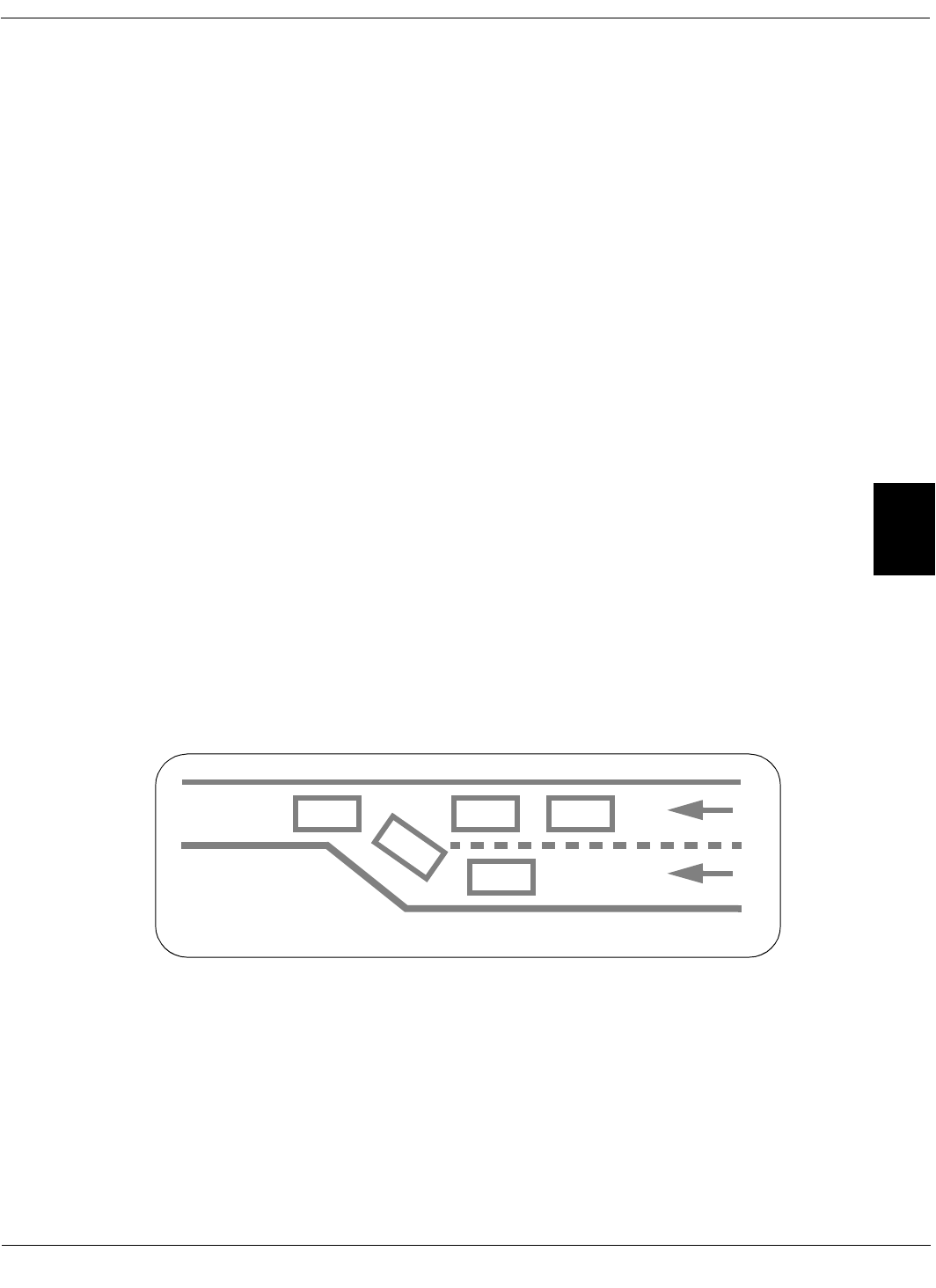
Documenting Software Architectures Clements, Bachmann, Bass, Garlan, Ivers, LIttle, Nord, Stafford
Copyright 2001 Addison Wesley, all rights reserved 44 Draft for review: Do not circulate without permission
IEEE Architecture Working Group. P1471 Recommended Practice for Architectural Description. The P1471
conceptual model records documentation beyond views as the concerns of the stakeholders and the environ-
ment.
Klein et al., WICSA, 1999. Attribute-based architectural styles (ABASs) provide a prepackaged analysis frame-
work and can be used when the architecture issue is a quality attribute and the solution is a style.
Meszaros and Doble, A Pattern Language for Pattern Writing. An example of a means of capturing the docu-
mentation beyond views. The authors capture best practices in pattern writing.
Rechtin and Maier, The Art of Systems Architecting. An example of capturing design guidelines. A collection of
strategies for designing system architecture.
Discussion questions
1. Think about a technical document that you know of and remember as being exceptionally use-
ful. What made it so?
2. Think of a technical document that you know of and remember as being dreadful. What made
it so?
3. For a system you’re familiar with, list several aspects that are architectural, and say why they are. List sev-
eral aspects that are not architectural, and say why they are not. List several aspects that are “on the cusp,”
and make a compelling argument for putting each into “architectural” or “non-architectural” categories.
4. If you visit Seoul, Korea, you might see the sign below presiding over one of the busy downtown thorough-
fares:
What does it mean? Is the information it conveys structural, behavioral, or both? What are the elements in
this system? Are they more like modules or components? What qualities about the notation are there that
makes this sign understandable (or not understandable)? Does it convey a dynamic architecture, or
dynamic behavior within a static architecture? Who are the stakeholders for this sign? What quality
attributes is it attempting to achieve? How would you validate it, to assure yourself that it was satisfying its
requirements?
5. List the stakeholders for a software architecture. How do project managers, Chief Technical Officers, Chief
Information Officers, analysts, customers, and end users fit into your list?
?
4
3
2
1 5

Copyright 2001 Addison Wesley, all rights reserved 45 Draft for review: Do not circulate without permission
6. How much of a project's budget would you devote to architecture documentation? Why? How would you
measure the cost and the benefit?
7. Which views have you found useful in software systems you've seen in the past? Which have you not
found useful? Why?
8. Other complex (non-software) systems make use of views as well. Physiology and house-building are ex-
amples. Think of others. In what ways do analogies like these make sense and in what ways do they break
down?
9. The three viewtypes in this book are based on the types of elements and relations native to each. This is
an organization based on structural characteristics. There are other ways to create and group views -- by
usage, for example. What are the advantages and disadvantages of each approach?
10. Do you think the analogy to building architecture styles makes a good or poor analogy to styles in software
architecture? Why or why not?
11. Is it possible that advances in programming, programming language technology, or middleware would
make obsolete the concept of documenting architecture through separate views?
References (to be moved to central Bibliography in back)
[Bachmann 00] Bachmann, F., Bass, L., Chastek, G., Donohoe, P., Peruzzi, F., “The Architec-
ture Based Design Method”, Carnegie Mellon University, Software Engineering
Institute Technical Report CMU/SEI-2000-TR-001, 2000.
[Bass 98] Bass, L., Clements, P., Kazman, R., Software Architecture in Practice, Addison-
Wesley, 1998.
[Bosch 00] Bosch, J., Design and Use of Software Architectures, Addison-Wesley, 2000.
[Clements 01] Clements, P., Kazman, R., and Klein, M. Evaluating Software Architectures:
Methods and Case Studies. Addison Wesley, 2001.
[Dijkstra 68] Dijkstra, E. W., “The structure of the ‘T.H.E.’ multiprogramming system,” CACM,
vol. 18, no. 8, 453-457, 1968.
[Hofmeister 00] Hofmeister, C., Nord, R., Soni, D., Applied Software Architecture, Addison-
Wesley, 2000.
[Jazayeri 00] Jazayeri, M., Ran, A., and van der Linden, F. Software Architecture for Product
Families: Principles and Practice, Addison Wesley, 2000.
[Kruchten 98] Kruchten, P. The Rational Unified Process: An Introduction. Reading, Ma.: Ad-
dison-Wesley, 1998.
[Malveau 01] Malveau, Raphael, and Mowbray, Thomas. Software Architect Bootcamp,
Prentice Hall PTR, Upper Saddle River, NJ, 2001.
[Parnas 72] Parnas, D., “On the Criteria To Be Used in Decomposing Systems into Mod-
ules”, Communications of the ACM, 15(12), December 1972, 1053-1058.

Documenting Software Architectures Clements, Bachmann, Bass, Garlan, Ivers, LIttle, Nord, Stafford
Copyright 2001 Addison Wesley, all rights reserved 46 Draft for review: Do not circulate without permission
[Parnas 74] Parnas, D., “On a ‘buzzword’: hierarchical structure,” Proceedings IFIP Con-
gress 74, 336-3390, 1974.
[SEI ATA] WWW: <URL: http://www.sei.cmu.edu/ata/ata_init.html>
[Shaw 96] Shaw, M., Garlan, D., Software Architecture: Perspectives on an Emerging Dis-
cipline. Prentice Hall, 1996.
[Smith 01] Smith, C.; & Williams, L. Performance Solutions: A Practical Guide for Creating
Responsive, Scalable Software. Reading, Ma.: Addison-Wesley, 2001.

Copyright 2001 Addison Wesley, all rights reserved 47 Draft for review: Do not circulate without permission
Part I:
Software Architecture
Viewtypes and Styles

Documenting Software Architectures Clements, Bachmann, Bass, Garlan, Ivers, LIttle, Nord, Stafford
Copyright 2001 Addison Wesley, all rights reserved 48 Draft for review: Do not circulate without permission
Chapter 1: The Module Viewtype
1.1 Overview: What is the Module Viewtype?
In this chapter and the next we look at ways to document the modular decomposition of a system’s software.
Such documentation enumerates the principal implementation units -- or modules -- of a system, together with
the relationships among these units. Generically we will refer to these descriptions as module views. As we will
see, these views can be used for each of the purposes outlined in the Prologue: education, communication
among stakeholders, and as the basis for analysis.
Modules emerged in the 1960’s and 1970’s based on the notion of software units with well-defined interfaces
providing some set of services (typically procedures and functions), together with implementations that hide (or
partially hide) their internal data structures and algorithms. More recently, these concepts have found wide-
spread use in object-oriented programming languages and modeling notations such as the UML.
Today the way in which a system’s software is decomposed into manageable units remains one of the important
forms of system structure. At a minimum it determines how a system’s source code is partitioned into separable
parts, what kinds of assumptions each part can make about services provided by other parts, and how those
parts are aggregated into larger ensembles. Choice of modularization will often determine how changes to one
part of a system might affect other parts, and hence the ability of a system to support modifiability, portability,
and reuse.
As such, it is unlikely that the documentation of any software architecture can be complete without at least one
view in the module viewtype.
We will start out by considering the module viewtype in its most general form. In the next chapter we identify
four common styles:
• The decomposition style is used to focus on “containment” relationships between modules.
• The uses style indicates functional dependency relationships between modules.
• The generalization style is used (among other things) to indicate specialization relationships between
modules.
• The layers (or layered) style is used to indicate the “allowed to use” relation in a restricted fashion
among modules.
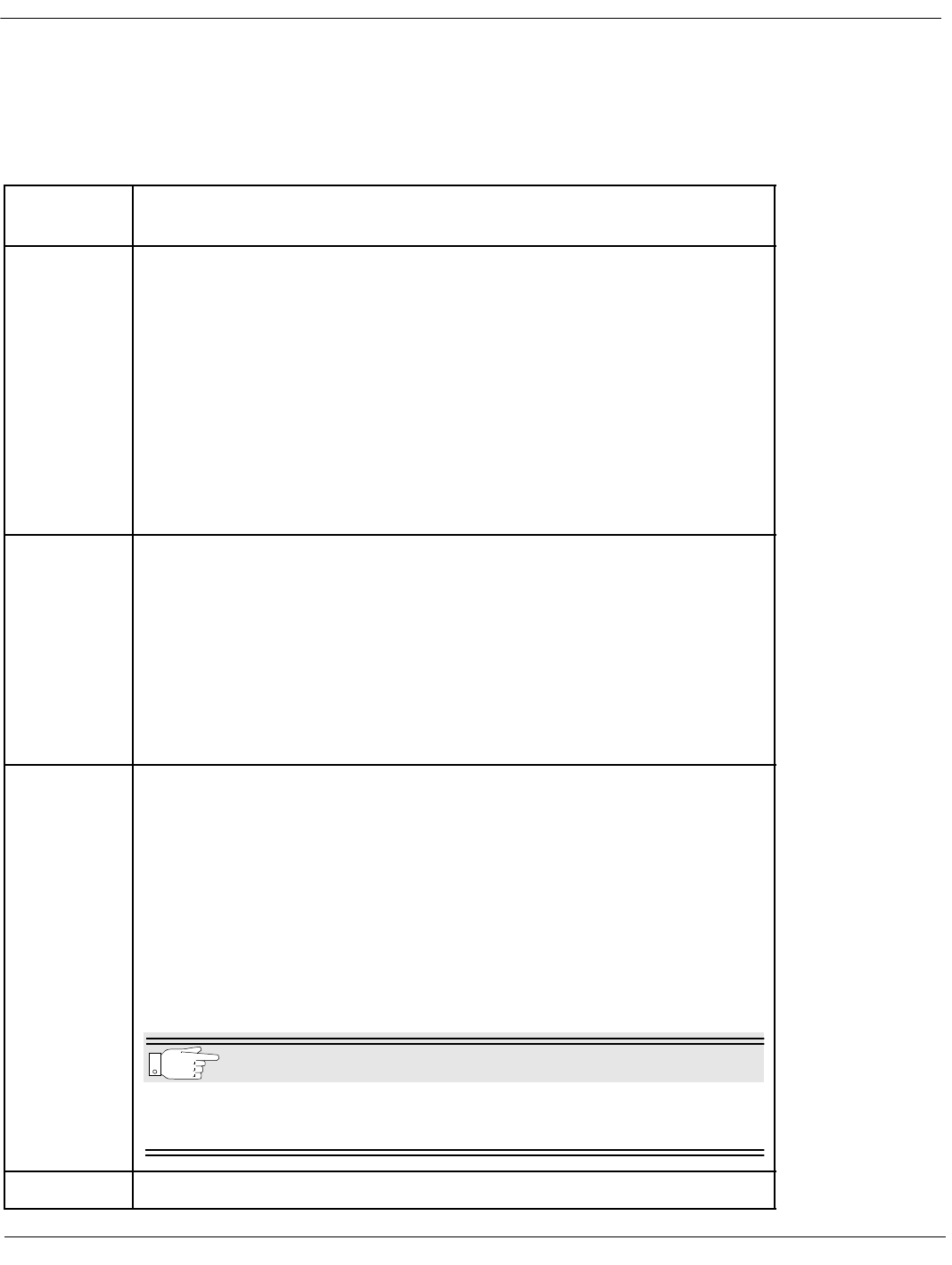
Chapter 1: The Module Viewtype
Copyright 2001 Addison Wesley, all rights reserved 49 Draft for review: Do not circulate without permission
1.2 Elements, Relations, and Properties of the Module Viewtype
Table 2 summarizes the elements, relations, and properties of the module viewtype.
Table 2: Summary of the module viewtype
Elements The element of a module view is a module, which is a unit of functional-
ity that implements a set of responsibilities
Relations Relations shown in a module view will be some form of is part of,
depends on, or is a.
• A is part of B defines a part-whole relation between the
submodule A (the part, or child) and the aggregate module B (the
whole, or parent).
• A depends on B defines a dependency relation between A and
B. Specific module styles will elaborate what dependency is
meant.
• A is a B defines a generalization relation between a more
specific module (the child A) and a more general module (the
parent B).
Properties
of elements
Properties of a module include:
• name, which may have to comply to rules such being a member
of a namespace
• responsibilities of the module
• visibility of the module’s interface(s) [applies when the relation is
a form of is part of]
• implementation information, such as the set of code units that
implement the module
Properties
of relations
• the is part of relation may have a visibility property associated
with it that defines if a submodule is visible outside the aggregate
module
• the depends on relation can have constraints assigned to specify
in more detail what the dependency between two modules is.
• The is a relation may have an implementation property, denoting
that a more specific module (the child A) inherits the
implementation of the more general module (the parent B), but
does not guarantee to support the parent’s interface and thereby
does not provide substitutability for the parent.
For more information...
Substitutability is discussed in the sidebar
on page tbd. [not yet written -- DG to
write]
Topology The module viewtype has no inherent topological constraints.

Documenting Software Architectures Clements, Bachmann, Bass, Garlan, Ivers, LIttle, Nord, Stafford
Copyright 2001 Addison Wesley, all rights reserved 50 Draft for review: Do not circulate without permission
Elements
The term “module” is used by system designers to refer a variety of software structures, including programming
language units (such as Ada packages, Modula modules, Smalltalk or C++ classes), or simply general group-
ings of source code units. In this book we adopt a broad definition:
Definition
A module is an implementation unit of software that provides a coherent unit of
functionality.
We characterize a module by enumerating a set of responsibilities, which are foremost among a module’s prop-
erties. This broad notion of “responsibilities” is meant to encompass the kinds of features that a unit of software
might provide, including services as well as internal and external state variables.
Modules can both be aggregated and decomposed. Different module views may identify a different set of mod-
ules and aggregate or decompose them based on different style criteria. For example, the layered style identi-
fies modules and aggregates them based on an allowed-to-use relation, whereas the generalization view
identifies and aggregates modules based on what they have in common.
Relations
The relations of the module viewtype are:
• is part of. A is part of B defines a part-whole relation between the submodule A (the part) and the
aggregate module B (the whole). In its most general form, the relation simply indicates some form of
aggregation, with little implied semantics. In general, for instance, one module might be included in
many aggregates. There are, however, stronger forms of this relation. An example can be found in the
module decomposition style in Chapter 2, where this relation is refined to a decomposition relation.
• depends on. A depends on B defines a dependency relation between A and B. This relation is typically
used early in the design process when the precise form of the dependency has yet to be decided. Once
the decision is made then depends on usually is replaced by a more specific form of the relation. Later
we will take a look at two in particular: uses and allowed to use, in the module uses and layered styles,
respectively. Other, more specific examples of the depends on relation include shares data with and
calls. A call dependency may further be refined to sends data to, transfers control to, imposes ordering
on, and so forth.
• is a. A is a B defines a generalization relation between a more specific module (the child A) and a more
general module (the parent B). The child is able to be used in contexts where the parent is used. We
will look at its use more detailed in the module generalization style. Object-oriented inheritance is
special case of the is-a relation.
Properties
As we will see in Section 10.1 ("Documenting a view"), properties are documented as part of the supporting
documentation for a view. The actual list of properties pertinent to a set of modules will depend on many things,
but is likely to include the ones below.

Chapter 1: The Module Viewtype
Copyright 2001 Addison Wesley, all rights reserved 51 Draft for review: Do not circulate without permission
• Name. A module’s name is, of course, the primary means to refer to it. A module’s name often suggests
something about its role in the system: a module called “account_mgr,” for instance, probably has little
to do with numeric simulations of chemical reactions. In addition, a module’s name may reflect its
position in some decomposition hierarchy; e.g., a name such as A.B.C.D refers to a module D that is
a submodule of a module C, itself a submodule of B, etc.
• Responsibilities. The responsibility for a module is a way to identify its role in the overall system, and
establishes an identity for it beyond the name. Whereas a module’s name may suggest its role, a
statement of responsibility establishes it with much more certainty. Responsibilities should be
described in sufficient detail so that it is clear to the reader what each module does.
Further, the responsibilities should not overlap. It should be possible, given a responsibility, to
determine which module has that responsibility. Sometimes it might be necessary to duplicate specific
responsibilities in order to support some qualities of the system such as performance or reliability. In
this case describe the duplicated responsibilities by stating the condition of use. For example, module
A might be responsible for controlling a device during normal operation. But there is also a module B,
which has higher performance but less features, that takes over during times of high processor load.
For more information...
In "Examples of the Decomposition Style" on page 64, we’ll show an extended example
of documenting a set of modules’ responsibilities.
• Visibility of interface(s). An interface document for the module establishes the module’s role in the
system with precision by specifying exactly what it may be called upon to do. A module may have zero,
one, or several interfaces.
In a view documenting an is-part-of relation, some of the interfaces of the submodules exist for internal
purposes only, that is, they are used only by the submodules within the enclosing parent module. They
are never visible outside that context and therefore they do not have a direct relation to the parent
interfaces.
Different strategies can be used for those interfaces that have a direct relationship to the parent
interfaces. The strategy shown in Figure 4(a) is encapsulation in order to hide the interfaces of the
submodules. The parent module provides its own interfaces and maps all requests using the
capabilities provided by the submodules. However, the facilities of the enclosed modules are not
available outside the parent.
Alternatively, the interfaces of an aggregate module can be a subset of the interfaces of the aggregate.
That is, an enclosing module simply aggregates a set of modules and selectively exposes some of their
responsibilities. Layers and subsystems are often defined in this way. For example, if module C is an
aggregate of modules A and B then C’s (implicit) interface will be some subset of the interfaces of
Modules A, B. (See Figure 4(b).).
For more information...
Interfaces are discussed in Chapter 11 ("Documenting Software Interfaces").
• Implementation information. Since modules are units of implementation, information related to their
implementation is very useful to record from the point of view of managing their development (and
building the system that comprises them). Although this information is not, strictly speaking,
architectural, it is highly convenient to record it in the architectural documentation where the module is
defined. Implementation information might include:

Documenting Software Architectures Clements, Bachmann, Bass, Garlan, Ivers, LIttle, Nord, Stafford
Copyright 2001 Addison Wesley, all rights reserved 52 Draft for review: Do not circulate without permission
– Mapping to code units. This identifies the files that constitute the implementation of a module. For
example, a module ALPHA, if implemented in C, might have several files that constitute its
implementation: ALPHA.c, ALPHA.h, ALPHA.o (if pre-compiled versions are maintained), and
perhaps ALPHA_t.h to define any data types provided by ALPHA.
For more information...
In addition to identifying the code units, one also needs to identify where the code units
reside in a project’s filing scheme: a directory or folder in a file system, a URL in an intra-
net, a storage location in a software engineering environment or tool set, or a branch,
node, and version in a configuration management system’s tree space. This information
is in the purview of the Implementation View, defined in Section 6.2.
– Test information. The the module’s test plan, test cases, test scaffolding, test data, and test history
are important to store.
– Management information. A manger may need the location of a module’s predicted completion
schedule and budget.
– Implementation constraints. In many cases, the architect will have a certain implementation
strategy in mind for a module, or may know of constraints that the implementation must follow. This
information is private to the module, and hence will not appear, for example, in the module’s
interface.
Styles in the module viewtype may have properties of their own in addition to these. In addition, you may find
other properties useful that are not listed.
A
C
BA
C
B
Key:
Module
Module interface
Figure 4: (a): Module C pro-
vides its own interface, hiding
the interfaces of modules A
and B
Figure 4(b): Module C exposes a
subset of the interfaces of mod-
ules A and B as its interface.

Chapter 1: The Module Viewtype
Copyright 2001 Addison Wesley, all rights reserved 53 Draft for review: Do not circulate without permission
1.3 What the Module Viewtype Is For and What It’s Not For
Expect to use the module viewtype for:
• Construction: The module view can provide a blueprint for the source code. In this case there is often
a close mapping between modules and physical structures, such as source code files and directories.
• Analysis: Two of the more important analysis techniques are requirements traceability and impact
analysis. Because modules partition the system, it should be possible to determine how the functional
requirements of a system are supported by module responsibilities. Often a high-level requirement will
be met by some sequence of invocations. By documenting such sequences, it is possible to
demonstrate to the customers how the system is meeting its requirements and also to identify any
missing requirements for the developers.
Another form of analysis is impact analysis, which helps to predict what the effect of modifying the
system will be. Context diagrams of modules that describe its relationships to other modules or the
outside world build a good basis for impact analysis. Modules are affected by a problem report or
change request. Please note that impact analysis requires a certain degree of design completeness
and integrity of the module description. Especially dependency information has to be available and
correct in order to create good results.
• Communication: A module view can be used to explain the system functionality to someone not
familiar with the system. The different levels of granularity of the module decomposition provide a top
down presentation of the systems’ responsibilities and therefore can guide the learning process.
It is difficult to use the module viewtype to make inferences about runtime behavior, because it is a partition of
the functions of the software. Thus, the module view is not typically used for analysis of performance, reliability,
or many other runtime qualities. For those we typically rely on Component and Connector and deployment
views.
For more information...
Chapter 3 and Chapter 4 cover C&C views; Chapter 6 covers deployment views.
1.4 Notations for the Module Viewtype
Information notations
A number of notations can be used in a module view’s primary presentation. One common, but informal notation
uses bubbles or boxes to represent the modules with different kinds of lines between them representing the
relations. Nesting is used to depict aggregation and arrows typically represent some form of depends on rela-
tion. Figure 4 above illustrates nesting to describe aggregation. In that figure small dots were used to indicate
interfaces, similar to the UML “lollipop” notation introduced in Section 11.5 ("Notation for Documenting Interfac-
es").
A second common form of notation is a simple textual listing of the modules with description of the responsibil-
ities and the interfaces for each. Various textual schemes can be used to represent the is part of relation, such
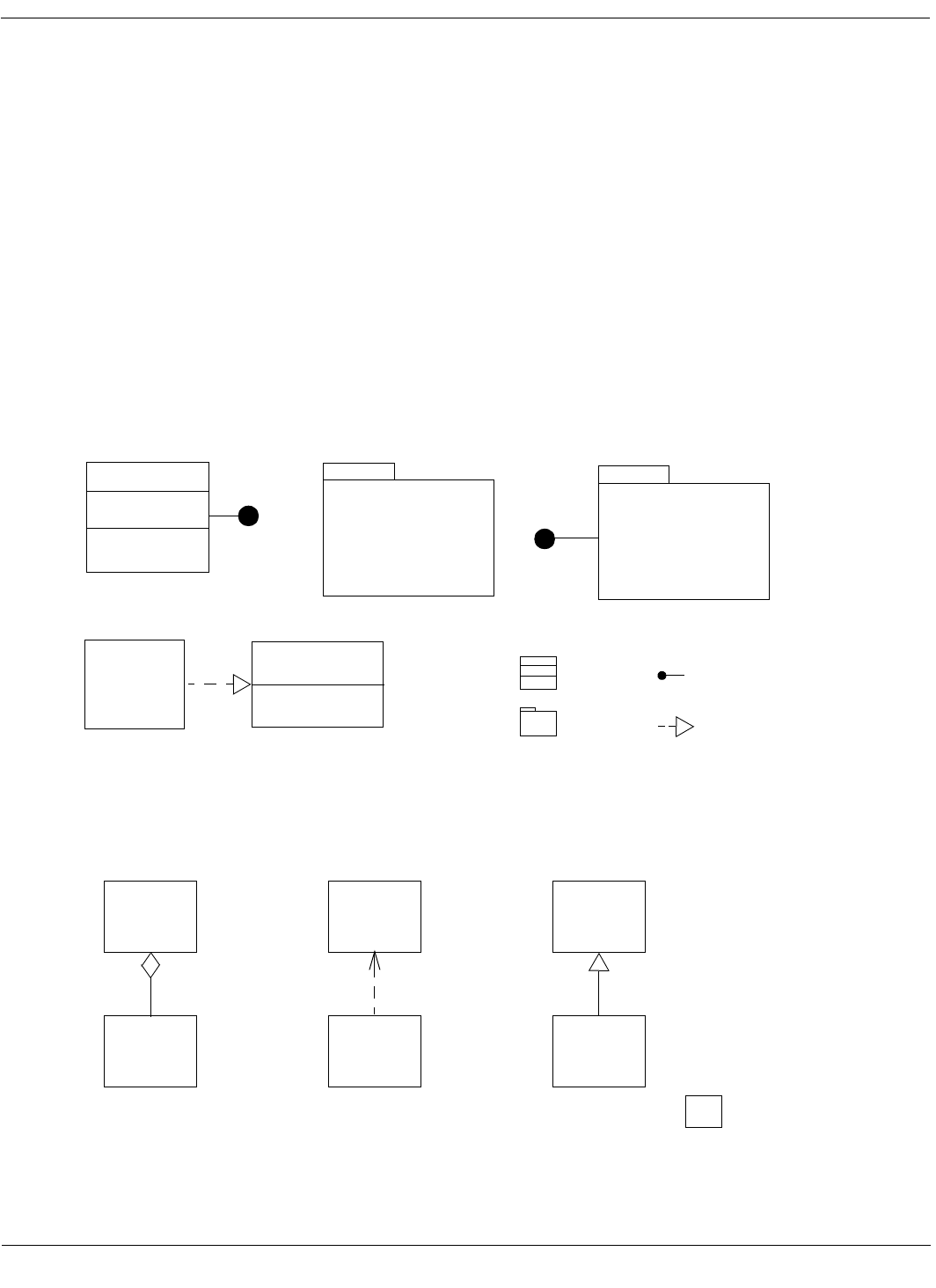
Documenting Software Architectures Clements, Bachmann, Bass, Garlan, Ivers, LIttle, Nord, Stafford
Copyright 2001 Addison Wesley, all rights reserved 54 Draft for review: Do not circulate without permission
as indentation, outline numbering, and parenthetical nesting. Other relations may be indicated by keywords.
For example: the description of module A might include the line “Imports modules B, C,” indicating a dependen-
cy between module A and modules B and C.
UML
Object modeling notations like UML provide a variety of constructs that can be used to represent different kinds
of modules. Figure 5 shows some examples for modules using UML notation. UML has a class construct, which
is the object-oriented specialization of a module as described here. As we will see, packages can be used in
cases where grouping of functionality is important, such as to represent layers and classes. The subsystem
construct can be used if specification of interface and behavior is required. An example for the use of sub-
systems can be found in the module decomposition style described in Chapter 2 ("Styles of the Module View-
type").
.
Figure 6 shows how the relations native to the module viewtype are denoted using UML.
<<subsystem>>
C
B
Subsystem
Figure 5: Examples of module notations in UML
Package
Class
Package
Interface
Key:
Class
A
Class
<<Interface>>
A
A
realizes
A
B
C
D
E
F
Aggregation Dependency Generalization
Figure 6: Examples of relation notations in UML. From left to right the diagrams read as follows:
module B is part of module A, module D depends on module C, and module F is a type of module E
is part depends on is a
Class
Key:

Chapter 1: The Module Viewtype
Copyright 2001 Addison Wesley, all rights reserved 55 Draft for review: Do not circulate without permission
1.5 Relation of Views in the Module Viewtype with Views in This and
Other Viewtypes
Module views are commonly mapped to views in the component-and-connector viewtype. The implementation
units shown in module views have a mapping to components that execute at run-time. Sometimes the mapping
is quite straightforward, even one-to-one. Often a single module will be replicated as many components; this
one-to-many mapping is also straightforward. However, the mapping can be quite complex, with fragments of
modules corresponding to fragments of components.
A common problem is the overloading of the module viewtype with information pertaining to other viewtypes.
Although when done in a disciplined fashion this can be quite useful, it can also lead to confusion. For example,
sometimes mechanisms such as RPC or the use of a CORBA infrastructure is included in the module viewtype.
Showing an RPC connection is implicitly introducing the “connector” concept from the component and connec-
tor viewtype.
The module views are often confused with views that demonstrate runtime relationships. A module view repre-
sents a partitioning of the software and so multiple instances of objects, for example, are not represented in this
view.
1.6 Glossary
subsystem
interface
module
interact
data flow
control flow
responsibilities
class
generalization
inheritance
operation
specialization

Documenting Software Architectures Clements, Bachmann, Bass, Garlan, Ivers, LIttle, Nord, Stafford
Copyright 2001 Addison Wesley, all rights reserved 56 Draft for review: Do not circulate without permission
information hiding
module aggregation
module composition
(Others TBD)
1.7 Summary checklist
tbd
1.8 For Further Reading
1. Booch, Jacobson, and Rumbaugh. The Unified Modeling Language User Guide.
Look at components and their relationships. Layers can be represented as packages.
There is no predefined stereotype for layers.
2. Buschmann, Meunier, Rohnert, Sommerlad, and Stal. A System of Patterns: Pattern Oriented Software Ar-
chitecture.
See the section describing the Layers pattern. Layers is an architectural pattern or a style with dynamic
properties.
3. Clements, Parnas, Weiss: “The Modular Structure of Complex Systems,” ICSE 1985 (?)...
4. D’Souza, Wills. Objects, Components, Frameworks with UML: The Catalysis Approach.
5. Hofmeister, Nord, and Soni. Applied Software Architecture, Addison-Wesley, 2000.
See chapter on the module architecture view. All systems have layers. The Layer structure (defined in the
module view) is distinct from styles defined in the conceptual view. This is a static view of the system where
the relation between layers is an abstraction of the provides/requires services relation between modules.
There can be a “layer style” in the conceptual view (with dynamic interactions) if this is what the domain
requires (but this is distinct from the module view notion of layers).
6. Rumbaugh, Jacobson, Booch. The Unified Modeling Language Reference Manual.
7. J. Palsberg and M.I. Schwartzbach. Three Discussions on Object-Oriented Typing. ACM SIGPLAN OOPS
Messenger, volume 3, number 2, 1992. Overview of sub-typing relationships
8. Selic, Gullekson, and Ward. Real-Time Object-Oriented Modeling.
Layers are fundamental to their model. Presents a comprehensive treatment of layers. Components have
ports for interactions and service access points/service provision points for the layering relation. Inter-layer
communication is not like component interaction in that there is no binding to individual components.
However in other ways it behaves as an interaction (i.e., they use the same message passing paradigm,
protocols, etc.). The relationship among layers is shown using arrows rather than adjacency.
9. Selic. UML for Realtime.
Defines UML stereotypes for layers.

Chapter 1: The Module Viewtype
Copyright 2001 Addison Wesley, all rights reserved 57 Draft for review: Do not circulate without permission
10. Shaw and Garlan. Software Architecture.
Present notion of levels of orthogonal styles, each level representing a virtual machine for the style in the
level above. See 3.5.3 A Blackboard Globally Recast as an Interpreter.
11. [BCK98]: Bass, Clements, Kazman: SAP.
A-7 example shows layers, defines uses and allowed to use, and shows how a subset is built from the uses
relation.
12. [PW76] D. L. Parnas, H. Wurges, “Response to Undesired Events in Software Systems,” Proceedings of
the Second International Conference on Software Engineering, October 1976, pp. 437-446.
13. [P79]: Parnas, D. L.; “Designing Software for Ease of Extension and Contraction,” IEEE Transactions on
Software Engineering, vol. SE-5, no. 2, pp. 128-137.
14. [DK76] Frank DeRemer and Hans H. Kron. Programming-in-the-Large versus Programming-in-the-Small.
IEEE Transactions on Software Engineering, SE-2(2):80-86, June 1976.
15. [PN86] R. Prieto-Diaz and J. M. Neighbors. Module Interconnection Languages. Journal of Systems and
Software, 6(4), November 1986, pp. 307-334.
1.9 Discussion questions
1. What is it possible and not possible to say about data flow by looking at a view in the module view-
type? What about control flow? What can you say about which modules interact with which other
modules?
2. Which properties of a module might you think of as worthy of having special notational conventions to ex-
press them, and why? For example, you might want to color a COTS module differently than modules de-
veloped in-house.
3. “Depends on” is a relation among modules, but is very general. What specific types of dependencies might
be reflected in a style in the module viewtype?
4. A primary property of a module is its set of responsibilities. How do a module's responsibilities differ from
the requirements that it must satisfy?
5. When documenting a particular system, you might wish to combine different modules into an aggregate,
for example to market them as a combined package. Would this package itself be a module? That is, are
all aggregates of modules themselves modules?
?

Documenting Software Architectures Clements, Bachmann, Bass, Garlan, Ivers, LIttle, Nord, Stafford
Copyright 2001 Addison Wesley, all rights reserved 58 Draft for review: Do not circulate without permission
Chapter 2: Styles of the Module Viewtype
We now look at four of the more common styles of the module viewtype:
• decomposition
• uses
• generalization
• layers
Each of these styles constraints the basic module viewtype, perhaps adding specialized versions of some of
module and relation types.
2.1 Decomposition Style
Overview of the Decomposition Style
By taking the elements and properties of the module viewtype and focusing on the is-part-of-relation, we get
the “module decomposition style”. You can use this style to show how system responsibilities are partitioned
across modules, and how those modules are decomposed into submodules. Compared to other styles of the
module viewtype, decomposition features fairly weak restrictions on the viewtype itself, but is usefully distin-
guished as a separate style for several reasons.
First, almost all architectures begin with it. Architects tend to attack a problem by divide-and-conquer, and a
view rendered in this style records their campaign. Second, a view in this style is a favorite tool with which to
communicate the broad picture of the architecture to newcomers. Third, this style begins to address the modi-
fiability that will be built into the architecture by allocating functionality to specific places in the architecture.
The criteria used for decomposing a module into smaller modules depend on what should be achieved by the
decomposition. To name some:
• achievement of certain qualities: For example, to support modification of software the design principle
of information-hiding calls for encapsulating changeable aspects of a system in separate modules, so
that the impact of any one change is localized. An other example is performance. Separating the
functionality that has higher performance requirements from the other functionality enables application
of different strategies, such as scheduling policy or judicious assignment to processors, for achieving
required performance throughout the various parts of the system.
• build versus buy. Some modules may be bought from the commercial marketplace (or reused intact
from a previous project) and therefore already have a set of functionality implemented. The remaining
functionality then must be decomposed around those bought modules.
• product lines. To support the efficient implementation of products of a product family it is essential to
distinguish between common modules, used in every or most products, and variable modules, which
differ across products.

Chapter 2: Styles of the Module Viewtype
Copyright 2001 Addison Wesley, all rights reserved 59 Draft for review: Do not circulate without permission
A decomposition view may represent the first pass at a detailed architectural design; the architect may subse-
quently introduce other stylistic conventions and (for example) evolve the decomposition view into a more de-
tailed uses, layered, or other module-based view. In that case, the decomposition view becomes a piece of
design history, and is included in the rationale that explains the origins of those other views in a system.
Elements, Relations, and Properties of the Decomposition Style
Elements of the decomposition style are modules, as described in Section 1.2 ("Elements, Relations, and Prop-
erties of the Module Viewtype"). Certain aggregations can be called subsystems (see “Coming to Terms: Sub-
systems”). The principal relation is the decomposition relation, which is a specialized form of the is-part-of
relation. This relation has as its primary property the guarantee that an element can only be a part of at most
one aggregate.
The decomposition relation may have a visibility property that defines if the submodules are visible only to the
aggregate module (the parent) or also to other modules. For a module to be visible means it can be used by
other modules. With this property an architect has some control over the visibility of modules as illustrated in
Figure 4. A decomposition relation in which no contained module is visible outside its parent is sometimes
called a containment relation.
Loops in the decomposition relations are not allowed, that is, a module cannot contain any of its ancestors. No
module can have more than one parent.
Coming to Terms
“Subsystem”
Table 3: Summary of the module decomposition style
Elements Module, as defined by the module viewtype. A module that aggregates
other modules is sometimes called a subsystem.
Relations The relation is the decomposition relation, which is a refined form of the
is-part-of relation. A documentation obligation includes specifying the
criteria used to define the decomposition.
Properties
of elements
As defined by the module viewtype
Properties
of relations
• Visibility, the extent to which the existence of a module is known, and
its facilities available, to those modules outside its parent.
Topology
• No loops are allowed in the decomposition relation.
• A module cannot be part of more than one module.

Documenting Software Architectures Clements, Bachmann, Bass, Garlan, Ivers, LIttle, Nord, Stafford
Copyright 2001 Addison Wesley, all rights reserved 60 Draft for review: Do not circulate without permission
When documenting a module view of a system, you may choose to identify certain aggregated modules
as subsystems. A subsystem can be (like many concepts in this field) pretty much anything you want it to
be, but it often describes a part of a system that (a) carries out some functionally cohesive subset of the
overall system’s mission; (b) can be executed independently; and (c) can be developed and deployed in-
crementally. An air traffic control system, for example, may be divided into several areas of capability:
• interpreting radar data to display aircraft positions on screens
• detecting aircraft that are about to violate separation constraints
• running simulations for training
• recording and playback for after-situation analysis and training
• monitoring its own health and status
Each of these might reasonably be called a subsystem. A subsystem, informally, refers to a portion of a
system that can be usefully considered separately from the rest.
But not just any portion of a system will do. At a minimum, a subsystem must exhibit some coherent useful
functionality. More than that, however, the term also suggests a portion of the system that can execute
more or less independently and directly supports the system’s overall purpose. In our air traffic control
application, for example, a math utilities library would certainly be a portion of a system, and an aggrega-
tion of modules. It even has coherent functionality. But it’s unlikely that the library would be called a sub-
system, because it lacks the ability to operate independently to do work that’s recognizably part of the
overall system’s purpose.
Subsystems do not partition a system into completely separate parts because some parts are used in
more than one subsystem. For example, if the air traffic control system looks like this:
...then a subsystem consists of one segment from the top layer, plus any segments of any lower layers
that it needs in order to carry out its functionality. A subset of the system formed in this way is often called
a slice or vertical slice.
The “more or less independent” nature of a subsystem makes it ideal for dividing up a project’s work. You
may, for example, ask an analyst to examine the performance of a subsystem. If a user’s interaction with
a system can be confined to a subsystem, then its security properties become important. A subsystem
can often be fielded and accomplish useful work before the whole system is complete. A subsystem
makes a very convenient package to hand off to a team (or subcontractor) to implement. The fact that it
executes more or less independently allows that team to work more or less independently even through
testing. Contrast this to an arbitrary module, which can certainly be assigned to a team for implementation,
but which probably requires the presence of other modules (or extensive scaffolding otherwise) to see it
through testing.
The UML world has co-opted the term to mean something quite specific, an aggregation of elements that
exhibits behavior (the collective behavior of the aggregated elements) and possibly offering one or more
interfaces (realized by the interfaces of the aggregated elements). From the UML specification:
A subsystem is a grouping of model elements, of which some constitute a specification of the
behavior offered by the other contained model elements... The contents of a Subsystem is (sic)
divided into two subsets: 1) specification elements and 2) realization elements. The former
provides, together with the Operations of the Subsystem, a specification of the behavior
contained in the Subsystem, while the ModelElements in the latter subset jointly provide a
Position
display
Monitoring
Recording &
playback
Collision
avoidance
Display generation
Simulation
Workstation scheduler
Network communications
Operating system

Chapter 2: Styles of the Module Viewtype
Copyright 2001 Addison Wesley, all rights reserved 61 Draft for review: Do not circulate without permission
realization of the specification... The purpose of the subsystem construct is to provide a grouping
mechanism with the possibility to specify the behavior of the contents. The contents of a
subsystem have the same semantics as that of a package... A subsystem has no behavior of its
own. All behavior defined in the specification of the subsystem is jointly offered by the elements
in the realization subset of the contents... Subsystems may offer a set of interfaces. This means
that for each operation defined in an interface, the subsystem offering the interface must have a
matching operation, either as a feature of the subsystem itself or of a use case. The relationship
between interface and subsystem is not necessarily one-to-one. A subsystem may realize several
interfaces and one interface may be realized by more than one subsystem. [UML spec, as quoted
to pc by felix via e-mail -- Felix, what is the exact reference? tbd]
The observation that a subsystem has no behavior (or interface) of its own except for the behavior (or
interfaces) of its aggregated parts corresponds to case (b) of Figure 4 on page 52. In UML, subsystems
are shown using a stereotyped package construct.
If you decide to identify subsystems in your design, make sure your rationale explains why you chose the
ones you did and what you plan to do with them.
|| END SIDEBAR/CALLOUT “Subsystem”
What the Decomposition Style Is For and What It’s Not For
A decomposition style view presents the functionality of a system in intellectually manageable pieces that are
recursively refined to convey more and more details. Therefore this style nicely supports the learning process
about a system. Beside the obvious benefit for the architect to support the design work, this view is an excellent
learning and navigation tool for newcomers in the project or other people that do not necessarily have the whole
functional structure of the system memorized. The grouping of functionality shown in this view also builds a use-
ful basis for defining configuration items within a configuration management framework.
The decomposition style most often serves as the input for the work assignment view of a system, which maps
parts of a software system onto the organizational units (teams) that will be given the responsibility for imple-
menting and testing them.
For more information...
The work assignment style is presented in Section 6.3.
The module decomposition view also provides some support for analyzing effects of changes at the software
implementation level, but since this view does not show all the dependencies among modules you cannot ex-
pect to do a complete impact analysis. Here views that elaborate the dependency relationships more thoroughly
such as the module uses style described later, are required.

Documenting Software Architectures Clements, Bachmann, Bass, Garlan, Ivers, LIttle, Nord, Stafford
Copyright 2001 Addison Wesley, all rights reserved 62 Draft for review: Do not circulate without permission
Notations for the Decomposition Style
Informal notations
In informal notations, modules in the decomposition style are usually depicted as named boxes that contain
other named boxes. Containment can also be shown using indentation (as in Figure 8 on page 64).
The nesting notation can employ a thick border suggesting opaqueness (and explained in the key), indicating
that children are not visible outside. Similarly, different kinds of arcs can be used to indicate containment (i.e.,
non-visibility) as opposed to ordinary is-part-of. If a visual notation is not available for indicating visibility, then
it can be defined textually.
Other properties (especially the modules’ responsiblities) are given textually.
UML
In UML, the subsystem construct (see Figure 73 on page 278) can be used to represent modules that contain
other modules; the class box is normally used for the leaves of the decomposition. Subsystems are both a pack-
age and a classifier. As a package, they can be decomposed and hence, are suitable for the aggregation of
modules. As a classifier, they encapsulate their contents and can provide an explicit interface.
Aggregation is depicted in one of three ways in UML:
• Modules may be nested inside one another (see Figure 7(a)).
• A succession of two diagrams (possibly linked) can be shown, where the second is a depiction of the
contents of a module shown in the first.
• An arc denoting composition is drawn between the parent and the children (see Figure 7(b)). In UML,
composition is a form of aggregation with implied strong ownership. That is to say, parts live and die
with the whole. So if module A is composed of modules B and C, then B or C cannot exist without the
presence of A. If A is destroyed at run-time, so are B and C. Thus, UML’s composition relation has
implications beyond just the structuring of the implementation units; the relation also endows the
elements with a run-time property as well. As an architect, you should make sure you are comfortable
with this property before using UML’s composition relation.

Chapter 2: Styles of the Module Viewtype
Copyright 2001 Addison Wesley, all rights reserved 63 Draft for review: Do not circulate without permission
Again, other properties, such as the modules’ responsibilities, are given textually, perhaps with an annotation.
Relation of the Decomposition Style to Other Styles
It is possible, and often desirable, to map between a module decomposition view and a component and con-
nector view. We will discuss this in greater detail after we have a chance to talk about components and connec-
tors. For now, it is sufficient to say that the point of providing such a mapping is to indicate how the software
implementation structures map onto run-time structures. In general this may be a many-to-many relationship.
The same module might implement several components or connectors. Conversely, one component might re-
quire several modules for its implementation. In some cases, the mapping is fairly straightforward; in others it
may be quite complex.
Finally, as mentioned above, the decomposition style is closely related to the work assignment style, a member
of the allocation viewtype. The work assignment style maps modules resulting from a decomposition to a set
of teams responsible for implementing and testing those modules.
A
B
D
C
B
C
D
A
Key:
Module
composition
Key:
Module that
contains modules
Module
Figure 7: (a): Showing decomposition in UML
with nesting. The aggregate module is shown as
a package.
Figure 7(b): Showing decomposition in UML
with arcs.

Documenting Software Architectures Clements, Bachmann, Bass, Garlan, Ivers, LIttle, Nord, Stafford
Copyright 2001 Addison Wesley, all rights reserved 64 Draft for review: Do not circulate without permission
Examples of the Decomposition Style
A-7E Avionics System
A decomposition example comes from the A-7E avionics software system described in [BCK98], Chapter 3.
Figure 8 shows the graphic part of the view. The figure names the elements and shows the “is part of” relation
among them for the A-7E system.
Hardware-Hiding Module
Extended Computer Module
Data Module
Input/Output Module
Computer State Module
Parallelism Control Module
Program Module
Virtual Memory Module
Interrupt Handler Module
Timer Module
Device Interface Module
Air Data Computer Module
Angle of Attack Sensor Module
Audible Signal Device Module
Computer Fail Device Module
Doppler Radar Set Module
Flight Information Displays Module
Forward Looking Radar Module
Head-Up Display Module
Inertial Measurement Set Module
Input-Output Representation Module
Master Function Switch Module
Panel Module
Projected Map Display Set Module
Radar Altimeter Module
Shipboard Inertial Nav. Sys. Mod.
Slew Control Module
Switch Bank Module
TACAN Module
Visual Indicators Module
Waypoint Info. System Module
Weapon Characteristics Module
Weapon Release System Module
Weight on Gear Module
Behavior-Hiding Module
Function Driver Module
Air Data Computer Module
Audible Signal Module
Computer Fail Signal Module
Doppler Radar Module
Flight Information Display Module
Forward Looking Radar Module
Head-Up Display Module
Inertial Measurement Set Module
Panel Module
Projected Map Display Set Module
Shipboard Inertial Nav. Sys. Mod.
Visual Indicator Module
Weapon Release Module
Ground Test Module
Shared Services Module
Mode Determination Module
Panel I/O Support Module
Shared Subroutine Module
Stage Director Module
System Value Module
Software Decision Module
Application Data Type Module
Numeric Data Type Module
State Transition Event Mod.
Data Banker Module
Singular Values Module
Complex Event Module
Filter Behavior Module
Physical Models Module
Aircraft Motion Module
Earth Characteristics Module
Human Factors Module
Target Behavior Module
Weapon Behavior Module
Software Utility Module
Power-Up Initialization Module
Numerical Algorithms Module
System Generation Module
System Generation Parameter Mod.
Support Software Module
Figure 8: The module decomposition view of the A-7E software architecture

Chapter 2: Styles of the Module Viewtype
Copyright 2001 Addison Wesley, all rights reserved 65 Draft for review: Do not circulate without permission
Except for the modules’ names, however, the figure shows none of the properties associated with this style.
Supporting the figure is textual documentation that explains the decomposition criteria, and for each module
lists
• its responsibilities
• its visibility to other modules outside its parent
• implementation information
In this example, the criterion for decomposition is the information-hiding principle, which holds that there should
be a module to encapsulate the effects each kind of change considered likely. A module’s responsibilities, then,
are described in terms of the information-hiding secrets it encapsulates.
In A-7E, the first-order decomposition produced three modules: hardware-hiding, behavior-hiding, and soft-
ware-decision-hiding. Each of these modules is decomposed into two to seven submodules. These are in turn
decomposed, and so forth, until the granularity is fine enough to be manageable. A useful design heuristic holds
that a module is small enough if it could be discarded and begun again if the programmer(s) assigned to imple-
ment it left the project.
This is how the A-7E module view documentation describes the responsibilities of the three highest-level mod-
ules:
begin some sort of typeset to indicate a quote:
• Hardware-hiding Module: The Hardware-Hiding Module includes the procedures that need to be
changed if any part of the hardware is replaced by a new unit with a different hardware/software
interface but with the same general capabilities. This module implements “virtual hardware” or an
abstract device that is used by the rest of the software. The primary secrets of this module are the
hardware/software interfaces. The secondary secrets of this module are the data structures and
algorithms used to implement the virtual hardware.
• Behavior-hiding Module: The Behavior-Hiding Module includes procedures that need to be changed if
there are changes in requirements affecting the required behavior. Those requirements are the primary
secret of this module. These procedures determine the values to be sent to the virtual output devices
provided by the Hardware-Hiding Module.
• Software Decision Module: The Software Decision Module hides software design decisions that are
based upon mathematical theorems, physical facts, and programming considerations such as
algorithmic efficiency and accuracy. The secrets of this module are not described in the requirements
document. This module differs from the other modules in that both the secrets and the interfaces are
determined by software designers. Changes in these modules are more likely to be motivated by a
desire to improve performance or accuracy than by externally imposed changes.
end example typeset
And this is how it describes the decomposition of the Software Decision Module into second-level modules (un-
less otherwise indicated, a module is visible outside its parent):
begin example typeset

Documenting Software Architectures Clements, Bachmann, Bass, Garlan, Ivers, LIttle, Nord, Stafford
Copyright 2001 Addison Wesley, all rights reserved 66 Draft for review: Do not circulate without permission
• Application Data Type Module: The Application Data Type Module supplements the data types
provided by the Extended Computer Module with data types that are useful for avionics applications
and do not require a computer dependent implementation. Examples of types include distance (useful
for altitude), time intervals, and angles (useful for latitude and longitude). These data types are
implemented using the basic numeric data types provided by the Extended Computer; variables of
those types are used just as if the types were built into the Extended Computer. The secrets of the
Application Data Type Module are the data representation used in the variables and the procedures
used to implement operations on those variables. Units of measurements (such as feet, seconds, or
radians) are part of the representation and are hidden. Where necessary, the modules provide
conversion operators, which deliver or accept real values in specified units.
• Data Banker Module: Most data are produced by one module and consumed by another. In most
cases, the consumers should receive a value as up-to-date as practical. The time at which a datum
should be recalculated is determined both by properties of its consumer (e.g., accuracy requirements)
and by properties of its producer (e.g., cost of calculation, rate of change of value). The Data Banker
Module acts as a “middleman” and determines when new values for these data are computed. The
Data Banker obtains values from producer procedures; consumer procedures obtain data from Data
Banker access procedures. The producer and consumers of a particular datum can be written without
knowing when a stored value is updated. In most cases, neither the producer nor the consumer need
be modified if the updating policy changes.
The Data Banker provides values for all data that report on the internal state of a module or on the state
of the aircraft. The Data Banker also signals events involving changes in the values that it supplies.
The Data Banker is used as long as consumer and producer are separate modules, even when they
are both submodules of a larger module. The Data Banker is not used if consumers require specific
members of the sequence of values computed by the producer, or if a produced value is solely a
function of the values of input parameters given to the producing procedure (such as sin(x)). The Data
Banker is an example of the use of the blackboard architectural style (see Chapter 4 -- tbd -- do we
cover blackboards there?).
The choice among updating policies should be based on the consumers’ accuracy requirements, how
often consumers require the value, the maximum wait that consumers can accept, how rapidly the
value changes, and the cost of producing a new value. This information is part of the specification given
to the implementor of the Data Banker.
• Filter Behavior Module: The Filter Behavior Module contains digital models of physical filters. They can
be used by other procedures to filter potentially noisy data. The primary secrets of this module are the
models used for the estimation of values based on sample values and error estimates. The secondary
secrets are the computer algorithms and data structures used to implement those models.
• Physical Models Module: The software requires estimates of quantities that cannot be measured
directly but can be computed from observables using mathematical models. An example is the time
that a ballistic weapon will take to strike the ground. The primary secrets of the Physical Models Module
are the models; the secondary secrets are the computer implementations of those models.
• Software Utility Module: The Software Utility Module contains those utility routines that would otherwise
have to be written by more than one other programmer. The routines include mathematical functions,
resource monitors, and procedures that signal when all modules have completed their power-up
initialization. The secrets of the module are the data structures and algorithms used to implement the
procedures.
• System Generation Module: The primary secrets of the System Generation Module are decisions that
are postponed until system-generation time. These include the values of system generation
parameters and the choice among alternative implementations of a module. The secondary secrets of
the System Generation Module are the method used to generate a machine-executable form of the
code and the representation of the postponed decisions. The procedures in this module do not run on
the on-board computer; they run on the computer used to generate the code for the on-board system.

Chapter 2: Styles of the Module Viewtype
Copyright 2001 Addison Wesley, all rights reserved 67 Draft for review: Do not circulate without permission
end example typeset
In the case of the A-7E architecture, this second-level module structure was enshrined in many ways: Design
documentation, on-line configuration-controlled files, test plans, programming teams, review procedures, and
project schedule and milestones all were pegged to this second-level module structure as their unit of refer-
ence. If you use a module decomposition structure to organize your project around, you need to pick a level of
the hierarchy as was done here, based on a granularity of modules that is manageable.
The module guide describes a third (and in some cases a fourth) level decomposition, but that has been omitted
here.
Mil-Std 498 CSCIs and CSCs
Readers familiar with U.S. military software standards such as MIL-STD-498 will recognize that CSCIs (which
stand for...tbd) and their constituent CSCs (...tbd) constitute a decomposition view of a system and nothing
more.

Documenting Software Architectures Clements, Bachmann, Bass, Garlan, Ivers, LIttle, Nord, Stafford
Copyright 2001 Addison Wesley, all rights reserved 68 Draft for review: Do not circulate without permission
2.2 Uses Style
Overview of the Uses Style
The uses style of the module viewtype comes about when the depends-on relation is specialized to uses.
For more information...
The sidebar “Coming to Terms: ‘Uses’ “on page 74 defines and discusses the uses rela-
tion in detail.
An architect may invoke this style to constrain the implementation of the architecture. This style tells developers
what they are and are not allowed to use when implementing their part of the system. This powerful style en-
ables incremental development and the deployment of useful subsets of full systems (see “What the Uses Style
Is For and What It’s Not For” on page 68).
Elements/Relations/Properties of the Uses Style
The element of this style is the module as in the module viewtype. We define a specialization of the depends
on relation to be the uses relation, where one module requires the correct implementation of another module
for its own correct functioning. This view makes explicit how the functionality is mapped to an implementation
by showing relationships among the code-based elements: which elements use which other elements to
achieve their function.
What the Uses Style Is For and What It’s Not For
This style is useful to plan incremental development, system extensions and subsets, debugging and testing,
and gauging the effects of specific changes.
Table 4: Summary of the module uses style
Elements Module as defined by the module viewtype.
Relations The relation is the uses relation, which is a refined form of the depends-
on relation. Module A uses module B if A depends on the presence of a
correctly functioning B in order to satisfy its own specification.
Properties
of elements
As defined by the module viewtype.
Properties
of relations
The uses relation may have a property that describes in more detail
what kind of uses one module makes of another.
Topology The uses style has no topological constraints. However, if there are
loops in the relation that contain many elements, the ability of the archi-
tecture to be delivered in incremental subsets will be impaired.

Chapter 2: Styles of the Module Viewtype
Copyright 2001 Addison Wesley, all rights reserved 69 Draft for review: Do not circulate without permission
Notations for the Uses Style
Informal notations
Informally, the uses relation is conveniently documented as a matrix, with the modules listed as rows and col-
umns. A mark in element (x,y) indicates and module x uses module y. The finest-grained modules in the de-
composition hierarchy should be the ones listed, since fine-grained information is needed to produce
incremental subsets.
The uses relation can also be documented as a two-column table, with using elements on the left and the ele-
ments they use listed on the right, as in Table 5 on page 72.
Informal graphical notations can show the relation using the usual box-and-line fashion.
For defining subsets, a tabular (that is, non-graphical) notation is preferred because it is easier to look up the
detailed relations in a table than find them in a picture, which will rapidly grow too cluttered to be useful except
in trivial cases.
UML
The uses style is easily represented in UML. The UML subsystem construct (see Figure 73 on page 278) can
be used to represent modules; the uses relation is depicted as a dependency with the stereotype <<use>>. In
Figure 9(a), the User Interface module is an aggregate module with a uses dependency on the DataBase mod-
ule. When a module is an aggregate, the decomposition requires that any uses relation involving the aggregate
module be mapped to a submodule using that relation. As illustrated in Figure 9(b), the User Interface module
is decomposed into modules A, B, and C. At least one of the modules must depend on the DataBase module
or the decomposition is not consistent.

Documenting Software Architectures Clements, Bachmann, Bass, Garlan, Ivers, LIttle, Nord, Stafford
Copyright 2001 Addison Wesley, all rights reserved 70 Draft for review: Do not circulate without permission
User
<<use>>
Data
Interface
Base
Data
Base
Module
A
Module
BC
<<use>>
<<use>>
<<use>>
Module
<<use>>
Key:
Module
uses relation
Figure 9: (a): Example of uses relation mapped to decomposed modules. Here, the User Interface
module is an aggregate module with a uses dependency on the DataBase module. We use the UML
Package notation here to represent modules, and the specialized form of “depends on” arrow to in-
dicate a uses relation.
Figure 9(b). Here is a refinement of Figure 9(a) showing that the User Interface module is decom-
posed into modules A, B, and C. At least one of the modules must depend on the DataBase module
or the decomposition is not consistent.
<<use>>
Key:
Module
uses relation

Chapter 2: Styles of the Module Viewtype
Copyright 2001 Addison Wesley, all rights reserved 71 Draft for review: Do not circulate without permission
The convention for showing interfaces explicitly and separate from elements that realize them can also be em-
ployed in a uses view. Figure 10 is an example in which the DataBase module has two interfaces, which are
used (respectively) by the User Interface and Administrative System modules.
Relation of the Uses Style to Other Styles
The uses style also goes hand-in-hand with the layers style, the governing relation of which is allowed-to-use.
An allowed-to-use view usually comes first, and contains coarse-grained directives defining the degrees of free-
dom for implementors. Once implementation choices have been made, the actual uses view emerges, and gov-
erns the production of incremental subsets.
Example of the Uses Style
The following table shows an example of a uses view from the A-7E avionics system, previously described. The
entries in the table are either modules (named in the decomposition view, shown in Figure 8 on page 64) or
interface programs (methods) in those modules. Where a module is named and not subsequently qualified, it
is shorthand for the list of all programs within that module.
User
<<use>>
<<interface>>
Interface
DataBase
DataBase
Figure 10: Using UML to represent the uses view, while showing interfaces explicitly. Here, the Data-
Base module has two interfaces, which are used by the User Interface and Administrative System
modules, respectively. The lollipop notation for interfaces would also work well here.
<<interface>>
DataBase
Administration
Query
Adminis-
System
<<use>>
trative
<<use>>
Key:
Module
uses relation
realizes
Interface

Documenting Software Architectures Clements, Bachmann, Bass, Garlan, Ivers, LIttle, Nord, Stafford
Copyright 2001 Addison Wesley, all rights reserved 72 Draft for review: Do not circulate without permission
Table 5: A-7E “Uses” view [tbd: cut down in size]
Using Programs Used Programs
Extended Computer Module (EC) None.
Device Interface Module (DI)
EC.DATA/PGM, EC.IO
b
, AT.NUM/STE.2.5.1, SU
Air Data Computer (ADC) PM.ECM, +DB.G_SS.Vertical_velocity_system+
Angle of Attack (AOA)
Audible Signal (AUD)
+S_BEEP_RATE+
EC.TIMER
b
All others
EC.PAR
b
/SMPH
Computer Fail Signal (CFS)
Doppler Radar Set (DRS)
Flight Information Displays (FID)
Forward Looking Radar (FLR)
+S_FLR_BLINK_RATE+
EC.TIMER
b
All others
DB.DI.MFSW, EC.PAR
b
/SMPH
Head-Up Display (HUD)
+S_HUD_BLINK_RATE+
EC.TIMER
b
All others
EC.PAR
b
/SMPH
Inertial Measurement Set (IMS) PM.ACM
Panel (PNL)
EC.PAR
b
/SMPH
Radar Altimeter (RA)
Shipboard Inertial Navigation Set (SINS)
EC.PAR
b
/SMPH
Slew Control (SLEW)
EC.PAR
b
/SMPH
Switch Bank (SWB)
EC.PAR
b
/SMPH
Tactical Air Navigation Set (TACAN)
Visual Indicators (VI)
+S_AUTOCAL_BLINK_RATE+
EC.TIMER
b
+S_NON_ALIGN_BLINK_RATE+
EC.TIMER
b
All others
Waypoint Information System (WIS)
Weapon Characteristics (WCM) DB.DI.WRS, +DB.G_SS.stik_quan+

Chapter 2: Styles of the Module Viewtype
Copyright 2001 Addison Wesley, all rights reserved 73 Draft for review: Do not circulate without permission
Weapon Release System (WRS) DB.DI.MFSW, EC.PAR*/SMPH
Weight on Gear (WOG)
EC.PAR
b
/SMPH
Function Driver Module (FD)
EC.DATA/PAR
b
/PGM/SMPH, AT.NUM/STE,
DB.SS.MODE/SS.PNL.INPUT/SS.STAGE/SS.SYS-
VAL, SVALSVAL, DB.DI
a
, SS.SUBRTN, SU
Air Data Computer Fns. (ADC) DB.DI.ADCR, DI.ADC, DI.ADCR, PM.FILTER
Audible Signal Fns. (AUD) DI.AUDSIG
Computer Fail Signal Fns. (CFS) DI.CFS, EC.STATE
Doppler Radar Fns. (DRS) DI.DRS
Flight Info Display Fns. (FID) DI.FID
Forward Looking Radar Fns. (FLR) DI.FLR
Head-Up Display Fns. (HUD) DI.HUD
Inertial Measurement Set Fns. (IMS) DB.DI.IMSR, DI.IMS, DI.IMSR
Panel Fns. (PNL)
EC.IO
b
, DB.SS.PNL.CONFIG, SS.PNL.FORMAT,
DI.ADCR, DI.IMSR, DI.PMDSR, DI.PNL
Projected Map Display Set Fns. (PMDS) DB.DI.PMDSR, DI.PMDS, DI.PMDSR
Shipboard Inertial Nav Set Fns. (SINS) DI.SINS
Visual Indicator Fns. (VI) DI.VI
Weapon Release Fns. (WRS) DI.WRS
Ground Test Fns. (GRT) Any program +TEST_…+ in EC.IO/MEM/PAR.1/TI
Any demand function AT.STE
Shared Services Module (SS)
EC.DATA/PGM/PAR
b
/SMPH, AT.NUM/STE.2.5.1,
SU
Mode Determination (MODE)
DB.DI
a
/PM.ACM
Stage Director (STAGE)
DB.DI.IMS
a
b
/PM.ACM
System Value (SYSVAL)
DB.DI
a
, PM.FILTER
Table 5: A-7E “Uses” view [tbd: cut down in size]
Using Programs Used Programs

Documenting Software Architectures Clements, Bachmann, Bass, Garlan, Ivers, LIttle, Nord, Stafford
Copyright 2001 Addison Wesley, all rights reserved 74 Draft for review: Do not circulate without permission
Table 5 names the elements of the view and stipulates the relations, but (except for element names) does not
document any of the elements’ or relations’ properties, as required by the view. These properties include the
elements’ responsibilities and implementation information, and must be given by supporting textual documen-
tation.
Coming to Terms
“Uses”
Two of the styles of the module viewtype that we present in this book (the uses style and the layered style)
are based upon one of the most under-utilized relations in software engineering: uses. The uses relation
is a special form of depends-on. A unit of software P
1
is said to use another unit P
2
if P
1
’s correctness
depends on P
2
being correct as well.
The uses relation resembles, but is decidedly not, the simple calls relation provided by most programming
languages. Here’s why:
• A program P
1
can use program P
2
without calling it. P
1
may assume, for example, that P
2
has left a
shared device in a usable state when it finished with it. Or P
1
may expect P
2
to leave a computed result
that it needs in a shared variable. Or P
1
may be a process that sleeps until P
2
signals an event to awak-
en it.
Panel I/O Support (PNL)
Input (INPUT) DB.DI.PNL, DB.DI.SWB, SS.PNL.CONFIG
Display format (FORMAT) DB.DI.PNL, DI.PNL
Configuration (CONFIG) DB.DI.PNL, DB.DI.SWB
Application Data Type Module (ADT) EC.DATA/PGM
Numeric Data Types (NUM)
State_Transition_Events (STE)
EC.PAR
b
/SMPH
Software Utility Module (SU) EC.DATA/PGM, AT.NUM/STE
Physical_Models_Module (PM) EC.DATA/PGM, AT.NUM/STE
Data Banker (DB)
Each submodule DB.x Corresponding module x where x is {DI PM SS}
Any_@T_or_@F_program AT.STE
a. Does not include any device reconfiguration program; these occur in the DI.ADCR, DI.IMSR, and DI.PMDSR
submodules. Does not include programs in the DI.MFSW submodule.
b. Does not include any program of the form +TEST_…+
Table 5: A-7E “Uses” view [tbd: cut down in size]
Using Programs Used Programs

Chapter 2: Styles of the Module Viewtype
Copyright 2001 Addison Wesley, all rights reserved 75 Draft for review: Do not circulate without permission
• A program P
1
might call program P
2
but not use it. If P
2
is an exception handler that P
1
calls when it
detects an error of some sort, P
1
will usually not care in the least what P
2
actually does. The figure below
shows an example: P
0
calls P
1
to accomplish some work, and depends on its result. (P
0
thus uses P
1
.)
Suppose P
0
calls P
1
incorrectly. Part of P
1
’s specification is that in case of error, it calls a program whose
name is passed to it by its caller
3
. Once P
1
calls that program, it has satisfied its specification. In this
case, P
1
calls (but does not use) P
2
. P
0
and P
2
may well reside in the same module, for P
2
is likely privy
to the same knowledge about what was intended as P
0
.
So “uses” is not “calls” or “invokes.” Likewise, “uses” is different from other depends-on relations such as
“includes” or “inherits from”. The “includes” relation deals with compilation dependencies, but need not
influence run-time correctness. The inheritance relation is also (usually) a pre-run-time dependency not
necessarily related to uses.
The uses relation imparts a powerful capability to a development team: It enables the ability to build small
subsets of a total system. Early in the project, this allows incremental development. Incremental develop-
ment is a development paradigm that allows early prototyping, early integration, and early testing. At every
step along the way, the system carries out some part of its total functionality (even if far from everything),
and does it correctly. Fred Brooks [MMM95] writes about the “electrifying effect on team morale” that is
caused by seeing the system first succeed at doing something. Absent incremental development, nothing
works until everything works, and we are reduced to the thoroughly discredited waterfall model of devel-
opment. Subsets of the total system are also useful beyond development. They provide a safe fallback in
even of slipped schedules: it is much better for the project manager to offer the customer a working subset
of the system at delivery time rather than apologies and promises. And a subset of the total system can
often be sold and marketed as a downscale product in its own right.
Here’s how it works. Choose a program that is to be in a subset; call it P
1
. In order for P
1
to work correctly
in this subset, correct implementations of the programs it uses must also be present. So include them in
the subset. For them to work correctly, their used programs must also be present, and so forth. The subset
consists of the transitive closure of P
1
’s uses
4
. Conceptually, you pluck P
1
out from the uses graph and
then see what programs come dangling beneath it. There’s your subset.
The uses relation must be carefully engineered to achieve the ability to extract useful subsets. That is, it
is part of the architect’s job to control what each program is allowed to use. If everything uses everything
(either directly or through transitive closure) then the uses relation is a jumbled mess. When you pluck
any program out of the graph, everything comes with it like a wadded up ball of string. Bringing any pro-
gram into a subset necessitates bringing every program into the subset, and incremental development
goes out the window.
The most well-behaved uses relation forms a hierarchy, a tree structure. Subsets are then defined by snip-
ping off subtrees. Life, and architecture, is seldom that simple, however, and the uses relation most often
forms a non-tree graph. Loops in the relation -- that is, for example, where P
1
uses P
2
, P
2
uses P
3
, and P
3
uses P
1
-- are the enemy of simple subsets. A large uses loop necessitates bringing in a large number of
programs (every member of the loop) into any subset joined by any member. “Bringing in a program”
means, of course, that it must be implemented, debugged, integrated, and tested. But the point of incre-
3.
Or perhaps it calls a program whose name was bound by parameter at system-generation time, or a program
whose name it looks up via some name server. Many schemes are possible.
4.
Of course, “calls” and other depends-on relations must be given their due. If a program in the subset calls,
includes, or inherits from another program but doesn’t use it, the compiler is still going to expect that program to
be present. But if it isn’t used, there need not be a correct implementation of it: a simple stub, possibly returning
some pro forma result, will do just fine.
P
2
P
1
calls, does not use
P
0
calls and uses
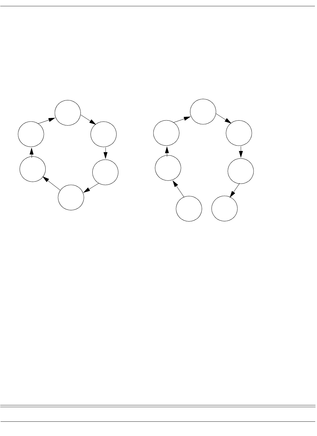
Documenting Software Architectures Clements, Bachmann, Bass, Garlan, Ivers, LIttle, Nord, Stafford
Copyright 2001 Addison Wesley, all rights reserved 76 Draft for review: Do not circulate without permission
mental development is that you’d like to bring in a small number of programs to each new increment, and
you’d like to be able to choose which ones you bring in, and not have them choose themselves.
A technique for breaking loops in the uses relation is called sandwiching. It works by finding a program in
the loop whose functionality is a good candidate for splitting in half. Say that program P
4
is in a uses loop.
We break program P
4
into two new programs, P
4A
and P
4B
. We implement them in such a way so that
• that they do not use each other directly
• the programs that used to use P
4
now use only P
4A
•P
4A
does not use any of the programs that the former P
4
used, but P
4B
does.
This breaks the loop, as Figure 11 illustrates.
Besides managing subsets, the uses relation is also a splendid tool for debugging and integration testing.
If you discover a program that’s producing incorrect results, then the problem is either going to be in the
program itself, or the programs that it uses. The uses relation lets you instantly narrow the list of suspects.
In a similar way, you can employ the relation to help you gauge the effects of proposed changes. If a pro-
gram’s external behavior changes as the result of a planned modification, you can backtrack through the
uses relation to see what other programs may be affected by that modification.
As originally defined by Parnas in 1979, the uses relation was a relation among “programs” or other rela-
tively fine-grained units of functionality. The modern analog would be methods of an object. Parnas wrote
that the uses relation was “conveniently documented as a binary matrix” where element (i,j) is true if and
only if program i uses program j. As with many relations, there are shorthand forms for documenting uses;
a complete enumeration of the ordered pairs is not necessary. For example, if a group of programs com-
prised by module A use another group of programs comprised by module B, then we can say that module
A uses module B. We can also say A uses B if some programs in A use some programs in B, as long as
you don’t mind bringing in all of module B to any subset joined by any program of module A. This makes
sense if module B is already implemented and ready to go, is indivisible for some reason (maybe it’s a
COTS product), or if its functionality is so intertwined that B cannot be teased apart. The main point about
size is that the finer-grained your uses relation is, the more control you have over the subsets you can
field and the debugging information you can infer.
|| END SIDEBAR/CALLOUT “Uses”
P
1
P
4
P
2
P
3
P
5
P
6
P
1
P
4B
P
2
P
3
P
5
P
6
P
4A
Figure 11: Using sandwiching to break loops in the uses relation. In the figure on the left, if any ele-
ment is a member of a subset, they all must be. In the figure on the right, P4 has been divided into two
parts that do not use each other directly. Now, including, say, P2 in a subset only necessitates inclu-
sion of a small number of additional elements. If P4B is desired in a subset, then the situation is as
before. But we could use sandwiching again on, say, P6 to shorten the uses chain.

Chapter 2: Styles of the Module Viewtype
Copyright 2001 Addison Wesley, all rights reserved 77 Draft for review: Do not circulate without permission
2.3 Generalization Style
Overview of the Generalization Style
The “generalization” style of the module viewtype comes about when the “is a” relation is specialized to “gen-
eralization” (see sidebar on Generalization). This style comes in handy when an architect wants to support ex-
tension and evolution of architectures and individual elements. Modules in this style are defined in such a way
that they capture commonalities and variations. When modules have a generalization relationship, then a mod-
ule (the parent) is a more general version of the other modules (the children)
5
. The parent module owns the
commonalities, while the variations are manifested in the children. Extensions can be made by adding, remov-
ing, or changing children; a change to the parent will automatically change all the children that inherit from it,
which would support evolution.
Generalization implies inheritance of both interface and implementation. The child inherits structure, behavior,
and constraints from its parent. Within an architectural description, the emphasis is on sharing and reusing in-
terfaces and not so much on implementations, although implementation reuse may be a by-product of extend-
ing the interface.
5.
Even though this style uses shares the terms “parent” and “child” with the decomposition style, they are quite dif-
ferent. In decomposition a parent consists of its children. In generalization, parents and children have things in
common.

Documenting Software Architectures Clements, Bachmann, Bass, Garlan, Ivers, LIttle, Nord, Stafford
Copyright 2001 Addison Wesley, all rights reserved 78 Draft for review: Do not circulate without permission
Elements/Relations/Properties of the Generalization Style
The element of the module generalization style is the module as defined by the module viewtype. We define a
specialization of the is a relation to be the generalization relation, where one module is a specialization of an-
other module (and the second is a generalization of the first).
A module can be an abstract module. That is, the modules only defines its interfaces but does not have an im-
plementation, at least not an implementation that is executable on its own. Children modules that comply to the
parents interface provide the necessary implementations.
In the transitive closure of the generalization relation, a module that inherits information is referred to as a de-
scendent, the module providing the information is an ancestor. Cycles are not allowed. That is, a module can
not be an ancestor or descendant of itself.
The generalization relation can be used in several different flavors to implement different strategies. If a module
A inherits from module B using the interface inheritance (see Figure 13(b)), then it is a promise that module A
complies at least to the public interface from B. Module A may also inherit and use behavior implemented by
module B, but this is not defined by this type of inheritance. This strategy is useful when different variants of a
module with very different implementations are needed and one implementation of the module can substitute
for another implementation with little or no effect on other modules.
With implementation inheritance (Figure 13(c)), a module inherits behavior from its ancestors and modifies it to
achieve its specialized behavior
6
. This usage of the generalization relation does not guarantee that the child
module complies to the interfaces of the parent module, Therefore, substitutability may be violated.
Table 6: Summary of the module generalization style
Elements Module as defined by the module viewtype.
Relations Generalization, which is the is a relation as in the module viewtype
Properties
of elements
Beside the properties defined for a module in the module viewtype, a
module can have the “abstract” property, that defines a module with
interfaces but no implementation.
Properties
of relations
The generalization relation can have a property that distinguishes
between interface and implementation inheritance. In case a module is
defined as an abstract module (the abstract property) then restricting
the generalization relationship to implementation inheritance is not
meaningful.
Topology
• a module can have multiple parents, although multiple inheritance is
considered a dangerous design approach in many places.
• Circles in the generalization relation are not allowed, that is any of the
child modules cannot be a generalization of one or more of its parent
modules.
6.
In UML, some classes are abstract classes, meaning they have no implementation. Since there is no implemen-
tation to inherit, implementation inheritance from an abstract class has no meaning.

Chapter 2: Styles of the Module Viewtype
Copyright 2001 Addison Wesley, all rights reserved 79 Draft for review: Do not circulate without permission
What the Generalization Style Is For and What It’s Not For
The module generalization style serves the following purposes:
• Object-oriented designs. The module generalization style is the predominant means for expressing
an inheritance-based object-oriented design for a system.
• Extension and evolution. It is often easier to understand how one module differs from another well
known module, rather than to try to understand a new module from scratch. Viewed this way,
generalization is a mechanism for producing incremental descriptions to form a full description of a
module.
• Local change or variation. One purpose of architecture is providing a stable global structure that
accommodates local change or variation. Generalization is one approach to define commonalities on
a higher level and define variations as children of this module.
• Reuse. Finding reusable modules is a by-product of the other purposes mentioned above. Suitable
abstractions can be reused at the interface-level alone, or the implementation can be included as well.
The definition of abstract modules creates an opportunity for reuse.
Background
Hierarchical Specialization
While the notion of inheritance is typically associated with the class style, it is also a useful technique for
imposing organizational structure on other architectural elements.
Inheritance relationships are used in descriptions of meta-models, styles, patterns, frameworks, or refer-
ence models more than in the description of a single system. Meta-models can be used to describe the
element hierarchy in the viewtypes or styles, for example. An element can be a module or component and
a module can be a class or a layer. Looking at this from the other way around, a class is a module is a
element. Patterns, frameworks, and reference modules describe a collection of elements and relations
that appear again and again in the description of different systems. Inheritance can be used in the archi-
tecture pattern itself. For example, in the MVC pattern, view and controller inherit from the observer so
that they are notified of event of interest. The user of the pattern may also use inheritance to specialize
the elements to the particular application.
Viewed this way, inheritance introduces the notions of architectural types and sub-typing. The subtype re-
lationship is used to evolve a given type to satisfy new requirements. This promotes off-the-shelf reuse
and analysis through type checking and conformance.
The UML refers to this organizing principle as generalization, making the distinction between generaliza-
tion as a taxonomic relationship among elements and inheritance as a mechanism for combining shared
incremental descriptions to form a full description of an element. Generalization implies inheritance of both
interface and implementation. The child inherits structure, behavior, and constraints from its parent.
When inheritance is used in defining architectural types, the elements should always be an abstract class,
thus avoiding the potential problems associated with implementation inheritance. An abstract class has
interfaces without implementations.
RN
|| END SIDEBAR/CALLOUT

Documenting Software Architectures Clements, Bachmann, Bass, Garlan, Ivers, LIttle, Nord, Stafford
Copyright 2001 Addison Wesley, all rights reserved 80 Draft for review: Do not circulate without permission
Notations for the Generalization Style
Expressing generalization lies at the heart of UML. Modules are shown as classes (although they may also be
shown as subsystems, as discussed in the decomposition style). Figure 12 shows the basic notation available
in UML.
Polygon Circle Spline
Polygon Circle Spline
Shape
Shape
Figure 12: Documenting generalization in UML. UML provides two line styles to show generaliza-
tion. These two diagrams are semantically identical. UML allows an ellipsis (...) in place of a submod-
ule. This indicates that a module can have more children than shown, and that additional ones are
likely. Module Shape is the parent of modules Polygon, Circle, and Spline, each of which is in turn a
subclass, child, or descendant of Shape. Shape is more general, while its children are specialized
...
...
...
Key:
Module
Generalization
Indicator that more
modules may be added

Chapter 2: Styles of the Module Viewtype
Copyright 2001 Addison Wesley, all rights reserved 81 Draft for review: Do not circulate without permission
Figure 13 shows how UML expresses interface and implementation inheritance.
Figure 14 shows how UML represents multiple inheritance. Whether or not this is a wise decision is question-
able, and outside the scope of this book.
realizes
generalization
Module or
interface
Key:
Figure 13: UML shows interface and implementation inheritance in different ways. tbd: beef up
this caption.
BB
AA
BB
<<Interface>>
BB
AA
… usually means Module A
inherits the implementation
of module B and realizes the
same interface as module B
Example 1: Generalization
relation without properties
A representation like this …
BB
AA
BB
<<Interface>>
BB
AA
… usually means Module A
realizes the same interface
as module B
Example 2: Generalization
using interface inheritance
A representation like this …
<<interface>>
BB
AA
BB
<<Interface>>
BB
AA
… usually means Module A
inherits the implementation
of module B but realizes its
own interface
Example 3: Generalization using
implementation inheritance
A representation like this …
<<implementation>>
AA
<<Interface>>

Documenting Software Architectures Clements, Bachmann, Bass, Garlan, Ivers, LIttle, Nord, Stafford
Copyright 2001 Addison Wesley, all rights reserved 82 Draft for review: Do not circulate without permission
Relation of the Generalization Style to Other Styles
Inheritance relationships complement the other module viewtype relations. For complex designs, it is useful
show inheritance relationships in a diagram separate from other types of relationships, such as decomposition.
Examples of the Generalization Style
tbd
Figure 14: Showing multiple inheritance in UML. tbd: beef up this caption
.
C
E
Module
Key:
generalization
D
Module C is a subclass,
child, descendent of
module D and E.
Module D and E
are the parents of
module C.
Using the generalization relation
in this way is questionable
because it may just be a
decomposition relation, such as
module C is decomposed into
modules D and E

Chapter 2: Styles of the Module Viewtype
Copyright 2001 Addison Wesley, all rights reserved 83 Draft for review: Do not circulate without permission
2.4 The Layered Style
Overview of the Layered Style
Layering, like all module styles, reflects a division of the software into units. In this case, the units are layers;
each layer represents a
virtual machine. Furthermore, there are constraints on the relationship among the vir-
tual machines. The layered view of architecture, shown with a layer diagram, is one of the most commonly used
views in software architecture. It is also poorly defined and often misunderstood. Because true layered systems
have good properties of modifiability and portability, architects have incentive to show their systems as layered,
even if they are not.
Coming to Terms
“Virtual machines”
A virtual machine (sometimes called an abstract machine) is a collection of modules that together pro-
vides a cohesive set of services that other modules can utilize without knowing how those services are
implemented. Programming languages such as C++ meet this definition: Although the ultimate result is
machine code that executes on one or more processors somewhere, we regard the instruction set pro-
vided by the language as the ultimate lingua franca of our program. We forget, happily, that without other
virtual machines underneath C++ (the operating system, the microcode, the hardware), our program
would just be a collection of alphanumeric characters that wouldn’t do anything.
Any module that has a public interface provides a set of services, but does not necessarily constitute a
virtual machine. The set of services must be cohesive with respect to some criterion. The services might
all appeal to a particular area of expertise (such as mathematics, or network communication). Or, they
might be native to some application area (such as maintaining bank accounts, or navigating an aircraft).
The goal of layering is to define virtual machines that are small enough to be well-understood, but com-
prehensive enough so the number of layers is intellectually manageable. Some of the criteria used in de-
fining the layers of a system are an expectation that the layers will evolve independently on different time
scales, that different people with different sets of skills will work on different layers, and that different levels
of reuse are expected of the different layers.
“”
“A program divided into a set of subprograms may be said to be hierarchically
structured, when the relation “uses” defines levels... The term “abstract machine”
is commonly used, because the relation between the lower level programs and
the higher level programs is analogous to the relation between hardware and
software.”
-- D. L. Parnas, “On a ‘Buzzword’: Hierarchical Structure”, 1974.
|| END SIDEBAR/CALLOUT “Virtual machines”

Documenting Software Architectures Clements, Bachmann, Bass, Garlan, Ivers, LIttle, Nord, Stafford
Copyright 2001 Addison Wesley, all rights reserved 84 Draft for review: Do not circulate without permission
To recap, layers completely partition a set of software, and each partition constitutes a virtual machine (with a
public interface) that provides a cohesive set of services. But that’s not all. The following figure (which is inten-
tionally vague about what the units are and how they interact with each other) shows three divisions of software
-- and you’ll have to take our word that each division is a virtual machine -- but none of them constitutes a lay-
ering. What’s missing?
Layering has one more fundamental property: The virtual machines are created to interact with each other ac-
cording to a strict ordering relation. Herein lies the conceptual heart of layers. If (A,B) is in this relation, we say
“layer B is beneath layer A”, and that means either, or both, of the following:
1. “The implementation of layer A is allowed to use any of the public facilities of the virtual machine provided
by layer B.”
2. “The public facilities in layer B are allowed to be used by the modules in layer A.”
By “use” and “used” we mean something very specific: A module A is said to
use unit B if A’s correctness de-
pends upon a correct implementation of B being present (see “Coming to Terms: ‘Uses’” on page 74).
There are some loopholes in the definition. If A is implemented using the facilities in B, is it implemented using
only B? Maybe; maybe not. Some layering schemes allow a layer to use the public facilities of any lower layer,
not just the nearest lower layer. Other layering schemes have “layers” that are collections of utilities and can be
used by any layer.
But no architecture that can be validly called “layered” allows a layer to use, without restric-
tion, the facilities of a higher layer
. (See the sidebar “Upwardly Mobile Software”) Allowing unrestricted upward
usage destroys the desirable properties that layering brings to an architecture; this will be discussed shortly.
Usage in layers generally flows downward. A small number of well-defined special cases may be permitted, but
these should be few and regarded as exceptions to the rule. Hence, the following architectural view
resembles
a layering, but is not:
Figures like the one above are why layers have been a source of ambiguity for so long, for architects have been
calling such things layered when they are not. There is more to layers than the ability to draw separate parts
on top of each other.
Key:
: allowed to use
A
B
C

Chapter 2: Styles of the Module Viewtype
Copyright 2001 Addison Wesley, all rights reserved 85 Draft for review: Do not circulate without permission
In many layered systems there will be situations in which modules of a lower layer will have to use (and there-
fore must be
allowed to use) modules in a higher layer and these usages will have to be accommodated by the
architecture. In other cases, modules in a very high layer might be required to directly use modules in a very
low layer where normally only next-lower-layer uses are allowed. The layer diagram (or an accompanying doc-
ument) will have to show these exceptions. The case of software in a higher layer using modules in a lower but
not the next-lower layer is called
layer bridging. If there are many of these, it is a sign of a poorly-structured
system (at least with respect to the portability and modifiability goals that layering helps to achieve). Systems
with upward usages are not, strictly according to the definition, layered. However, in such cases, the layered
view represents a close approximation to reality, and also conveys the ideal design that the architect’s vision
was trying to achieve.
Layers are intended to provide a virtual machine and one use of a virtual machine is to promote portability. For
this reason, it is important to scrutinize the interface of a layer to ensure that portability concerns are addressed.
The interface should not expose functions dependent on a particular platform; these functions should be hidden
behind a more abstract interface that is independent of platform.
Because the ordering relationship among layers has to do with “implementation allowed to use”, the lower the
layer the fewer the facilities available to it. That is, the “world view” of lower layers tends to be smaller and more
focused on the computing platforms. Lower layers tend to be built using knowledge of the computers, commu-
nications channels, distribution mechanisms, process dispatchers, and the like. These areas of expertise are
largely independent of the particular application that runs on them meaning they will not need to be modified if
the application changes.
Conversely, higher layers tend to be more independent of the platform; they can afford to be, because the ex-
istence of the lower layers has given them that freedom. They can afford to be more concerned only with details
of the application.
Observation
“Upwardly Mobile Software”
We have been downright pedantic about saying that upward uses invalidate layering. We made allowanc-
es for documented exceptions, but implied that too many of those would get you barred from the Software
Architect’s Hall of Fame.
Seasoned designers, however, know that in many elegantly-designed layered systems, all kinds of control
and information flow upward along the chain of layers with no loss of portability, reusability, modifiability,
or any of the other qualities associated with layers. In fact, one of the purposes of layers is to allow for the
“bubbling up” of information to the units of software whose scope makes them the appropriate handlers
of the information.
Error handling exemplifies this. The now-classic stack-based error propagation scheme was described by
Parnas in 1976 (using “undesired event” -- UE -- as the term for error):
...upon detecting a UE in a hierarchically structured piece of software, the UE is first reflected and control
passed to the level where it originated. At this point it is either corrected or reflected still higher... At every
level, either recovery is attempted or the UE is reported still higher. [PW76]

Documenting Software Architectures Clements, Bachmann, Bass, Garlan, Ivers, LIttle, Nord, Stafford
Copyright 2001 Addison Wesley, all rights reserved 86 Draft for review: Do not circulate without permission
The idea is that the software that caused the error is the best place to handle the error because the scope
and information are available there to do so. When a layer is ported to some other application or environ-
ment, not only does the functionality transfer but also the ability to handle any errors that might be precip-
itated by that functionality. It makes a nice matching set.
Suppose we have a simple three-layer system:
Say that program Pa in A uses program Pb in B which uses program Pc in C. If Pc is called in a way that
violates its specification, Pc needs a way to tell Pb “Hey! You called me incorrectly!” At that point, Pb can
either recognize its own mistake and call Pc again (this time correctly) or take some other action, or Pb
can realize that the error was due to the fact that it was called incorrectly (perhaps sent bad data) by Pa.
In the latter case, it needs a way to tell Pa “Hey! You called me incorrectly!”
Callbacks are a mechanism to manifest the protestation. We do not want Pc written with knowledge about
programs in B, or Pb written with knowledge about programs in A, since this would limit the portability of
layers C and B. Therefore the names of higher-level programs to call in case of error are passed down-
ward as data. Then the specification for, say, Pb includes the promise that in case of error it will invoke
the program whose name has been made available to it.
So there we have it: data and control flowing downward and upward in an elegant error-handling scheme
that preserves the best qualities of layers. So much for our prohibition about upward uses. Right?
Wrong. Upward uses are still a bad idea, but the scheme we just described doesn’t have any of those. It
has upward data flow and upward invocation, but not uses. The reason is that once a program calls its
error-handler, its obligation is discharged. The program does not use the error handler because its own
correctness depends not a whit on what the error handler does.
While this may sound like a mere technicality, it is an important distinction. Uses is the relation that deter-
mines the ability to reuse and port a layer. “Calls” or “sends data to” is not. An architect needs to know the
difference and needs to convey the precise meaning of the relations in his or her architectural documen-
tation.
|| END SIDEBAR/CALLOUT “Upwardly Mobile Software”
Some other observations about layers:
• Layers cannot be derived by examining source code. The source code may disclose what actually uses
what, but the relation in layers is
allowed to use. As a trivial example, you can tell by code inspection
that a “double” operation was implemented using multiplication by 2, but you cannot tell from the code
– whether it would have been equally acceptable to implement double(x) by adding x to itself or by
performing a binary left shift -- that is, what double(x) was allowed to use
– whether addition, double, and multiplication are in the same or different layers
• A layer may provide services that are not actually used by other modules. This occurs when the layer
was designed to be more general than is strictly necessary for the application in which it finds itself.
This in turn often occurs when the layer is imported from some other application, purchased as a
commercial product, or designed to be used for subsequent applications. This result, of course, can
occur in other styles as well as the layered style.
With this overview, we now complete our exposition of layers.
C
A
B

Chapter 2: Styles of the Module Viewtype
Copyright 2001 Addison Wesley, all rights reserved 87 Draft for review: Do not circulate without permission
Elements/Relations/Properties of the Layered Style
Elements
The elements of a layered diagram are layers. A layer is a cohesive collection of modules each of which may
be invoked or accessed. Each layer should represent a virtual machine. This definition admits many possibili-
ties, from or classes, to assembly language subroutines, and shared data. A requirement is that the units have
an interface by which their services can be triggered or initiated or accessed.
Relations
The relation among layers is allowed to use. If two layers are related by this relation, then any module in the
first is allowed to use any module in the second. A module A is said to
use another module B if A’s correctness
depends on B being correct as well.
The “end game” of a layers diagram is to define the binary relation “allowed to use” among modules. Just as
y=f(x) is a mathematical shorthand for enumerating all of the ordered pairs that are in the function f, a layer
diagram is a notational shorthand for enumerating all of the ordered pairs (A,B) such as A is allowed to use B.
A clean layer diagram is a sign of a well structured relation; when the layer diagram is not clean, then the layer
diagram will be rife with exceptions and appear chaotic.
Properties
Layers have the following properties, which should be documented in the catalog accompanying the layer dia-
gram:
Table 7: Overview of the layered style
Elements Layers.
Relations Allowed to use, which is a specialization of the module viewtype’s
generic “depends on” relation. P1 is said to use P2 if P1’s correctness
depends upon having a correct version of P2 present as well.
Properties
of elements
• Name of layer
• The units of software the layer contains
• The software a layer is allowed to use: (software in next lower layer,
software in any lower layer, exceptions to downward-only allowable
usage)
• The interface to the layer.
• The cohesion of the layer -- a description of the virtual machine
represented by the layer
Properties
of relations
• The relation is transitive.
Topology
• Every piece of software is allocated to exactly one layer.

Documenting Software Architectures Clements, Bachmann, Bass, Garlan, Ivers, LIttle, Nord, Stafford
Copyright 2001 Addison Wesley, all rights reserved 88 Draft for review: Do not circulate without permission
• Name: Each layer is given a name.
• Contents: The catalog for a layers view lists the software units contained by each layer. This document
assigns each module to exactly one layer. Layer diagrams will typically label the layers with descriptive
(but vague) names like “network communications layer” or “business rules layer” but a catalog is
needed that lists the complete contents of every layer.
• The software a layer is allowed to use: Is a layer allowed to use only the layer below, any lower layer,
or some other? Are modules in a layer permitted to use other modules in the same layer? This part of
the documentation must also explain exceptions, if any, to the usage rules implied by the geometry.
Exceptions may be upward (allowing something in a lower layer to use something above) or downward
(either prohibiting a specific usage otherwise allowed by the geometry, or by allowing downward usage
that “skips” intermediate layers normally required). Exceptions should be precisely described.
• The interface to the layer. If the interfaces are documented elsewhere, this can be a pointer.
• Cohesion: An explanation of how the layer provides a functionally cohesive virtual machine. A layer
provides a cohesive set of services, meaning that the services as a group would likely be useful as a
group in some other context than the one in which they were developed.
For example, suppose module P1 is allowed to use module P2. Should P2 be in a lower layer than P1,
or should they be in the same layer? Layers are not a function of just who-uses-what, but are the result
of a conscious design decision that allocates modules to layers based on considerations such as
coupling, cohesion, and likelihood of changes. In general, P1 and P2 should be in the same layer if they
are likely to be ported to a new application together, or if together they provide different aspects of the
same virtual machine to a usage community. This is an operational definition of cohesion.
The cohesion explanation can also serve as a
portability guide, describing the changes that can be
made to each layer without affecting other layers.
Observation
“Levels of Distraction
Our definition of layers is not the only one you’re likely to encounter. (It goes without saying, of course,
that ours is the best one.) Here is another definition, which is fairly typical, taken from a well-known con-
temporary book on software architecture:
The Layers architectural pattern helps to structure applications that can be decomposed into groups of
subtasks in which each group of subtasks is at a particular level of abstraction.
We would like to gently take exception with this definition, to illuminate and emphasize some concepts
that are at the heart of layers.
First, the definition above does not mention usage relationships. Suppose we can agree on what a sub-
task is, and suppose further that we can decompose our application into groups of subtasks that meet that
definition’s abstraction criterion. Do we have layers? By the definition above, we do. But we don’t buy it.
If every group of subtasks is allowed to use every other group, then this is by no stretch of the imagination
a layered system. The essence of a layered system is that lower layers do not have unrestricted access
to higher layers. Otherwise, the system will have none of the portability or maintainability benefits that lay-
ering is designed to provide, and so does not deserve to be called layered.
Second, “levels of abstraction” makes us shudder. Layers are often bound up with that unfortunate and
intellectually bankrupt phrase. We concede that the wretched thing is in wide use. It often pops up in shal-
low viewgraph presentations next to “synergistic” or the dubious noun “value-add”. It’s as pernicious as
kudzu; it probably snuck into this book once or twice while the censors were at lunch. But we try to eschew
it because it just smacks of sloppy thinking. Is 2 a valid level of abstraction? Is 3.14159? How about “Me-

Chapter 2: Styles of the Module Viewtype
Copyright 2001 Addison Wesley, all rights reserved 89 Draft for review: Do not circulate without permission
dium low?” The phrase suggests that abstractions can be measured on some discrete numeric scale, but
no such scale has ever been identified nor is one likely to be. As Parnas peevishly wrote in 1974, [Parnas,
D.L., “On a ‘Buzzword’: Hierarchical Structure”, IFIP Congress ‘74, North Holland Publishing Company,
1974, pp. 336-339] “It would be nice if the next person to use the phrase... would define the hierarchy to
which he refers.” Indeed. The phrase reveals a basic misunderstanding about abstractions, suggesting
that any two can be compared to each other to see which one is lower. This is rubbish. An abstraction is,
at its core, a one-to-many mapping. The “one” is the abstraction; the “many” is the set of things for which
the abstraction is a valid generalization. Mappings, which are a kind of relation, are not “higher” or “lower”
than each other. They merely differ from each other.
We wrote that layers towards the bottom of the allowed-to-use relation tend to cover details of the hard-
ware platform, while layers towards the top of the allowed-to-use relation tend to cover details of the ap-
plication. That is because applications tend to use platforms, and not the other way around. But neither
abstraction is “lower” nor “higher”. The application layer is completely ignorant of the machine, but knowl-
edgeable about the application. The machine layer is completely ignorant of the application, but knowl-
edgeable of the platform. They complement each other in an elegant symmetry (which is not to be
confused with synergy).
People tend to talk about the machine abstraction being “lower” because they have a layer (that is, an
allowed-to-use) picture already in mind; there’s nothing inherently “low” about a platform-encapsulating
layer otherwise. Thus, the definition we’re pillorying only makes sense if you already know what layers
are.
The definition is repairable. Had we written the offending book (Note to the authors: there are many other
parts of your book that we admire, and wish we had written) we might have offered something like this:
The Layers architectural pattern structures software systems that can be decomposed into groups of sub-
tasks in which each group of subtasks constitutes a cohesive abstraction of some aspect of the system
(and no two groups constitute the same abstraction of the system) and in which an “allowed to use” rela-
tion among the groups imposes a strict ordering
7
.
Abstractions are not inherently ordered, nor have levels, except in the presence of a usage relation. With-
out that, you don’t have layers. You just have groups of subtasks milling about waiting to be told how to
arrange themselves into a useful formation. Some might say the ordering brings a synergistic value-add
to the groups.
But I wouldn’t. The censors are back from lunch.
-- PCC
|| END SIDEBAR/CALLOUT “Levels of distraction”
What the Layered Style Is For and What It’s Not For
Layers help to bring quality attributes of modifiability and portability to a software system. A layer is an applica-
tion of the principle of information hiding -- in this case the virtual machine. The theory is that a change to a
lower layer can be hidden behind its interface and will not impact the layers above it. As with all such theories,
there is truth and there are caveats associated with the theory. The truth is that this technique has been used
with great success to support portability. Machine, operating system or other low level dependencies are hidden
within a layer and as long as the interface for the layer does not change, then the upper levels that depend only
on the interface will work successfully.
7.
Or a partial ordering. That would mean that some layers consist of more than one group, which are allowed to
use each other.

Documenting Software Architectures Clements, Bachmann, Bass, Garlan, Ivers, LIttle, Nord, Stafford
Copyright 2001 Addison Wesley, all rights reserved 90 Draft for review: Do not circulate without permission
The caveat is that “interface” means more than just the API containing program signatures. An interface em-
bodies
all of the assumptions that an external entity (in this case a layer) may make. Changes in a lower layer
that affect, say, a performance assumption will will leak through its API and may affect a higher layer.
For more information...
See “Coming to Terms: “Signature” “API” “Interface” on page 279.
A common misconception is that layers introduce additional runtime overhead. Although this may be true for
naive implementations, sophisticated compile-link-load facility can reduce additional overhead.
We have already mentioned that in some contexts, there may be unused services within a layer. These unused
services may needlessly consume some run-time resource (such as memory to store the unused code, or a
thread that is never launched). If these resources are in short supply, then, again, a sophisticated compile-link-
load facility that eliminates unused code will be helpful.
Layers are part of the blueprint role that architecture plays for constructing the system. Knowing the layers in
which their software resides, developers know what services they can rely on in the coding environment. Layers
might define work assignments for development teams (although not always).
Layers are part of the communication role played by architecture. In a large system, the number of dependen-
cies among modules rapidly expands. Organizing the modules into layers with interfaces is an important tool to
manage complexity and communicate the structure to developers.
Finally, layers help with the analysis role played by architecture: They support the analysis of the impact of
changes to the design by enabling some determination of the scope of changes.
Notations for the Layered Style
Informal Notations
Stack: Layers are almost always drawn as a stack of rectangles atop each other. The “allowed to use” relation
is denoted by geometric adjacency, and read from the top down, like this:
A
B

Chapter 2: Styles of the Module Viewtype
Copyright 2001 Addison Wesley, all rights reserved 91 Draft for review: Do not circulate without permission
Layering is thus one of the few architectural styles in which connection among components is shown by geo-
metric adjacency and not some explicit symbology such as an arrow, although arrows can be used, like this:
Rings: The most common notational variation is to show layers as a set of concentric circles or rings. The in-
nermost ring corresponds to the lowest layer. The outermost ring corresponds to the highest layer. A ring may
be subdivided into sectors, meaning the same thing as the corresponding layer being subdivided into parts.
There is no semantic difference between a layer diagram that uses a “stack of rectangles” paradigm and one
that uses the “ring” paradigm -- except in the case of segmented layers with restrictions on the “allowed to use”
relationship within the layer. We now discuss this special case.
In the figure on the left below, assume that segments in the same ring that touch each other are allowed to use
each other. The corresponding rule in the “stack” picture would be that segments in the same layer that touch
each other are allowed to use each other. There is no way to “unfold” the ring picture to produce a stack picture
(such as the one on the right) with exactly the same meaning, because circular arrangements allow more ad-
jacencies than linear arrangements. (In the figure on the right, B1 and B3 are separate, whereas in the figure
on the left they are adjacent.) Cases like this are the only ones where a ring picture can show a geometric ad-
jacency that a stack picture cannot.
Segmented layers. Sometimes layers are divided into segments denoting some finer-grained aggregation of
the modules. Often this occurs when there is some pre-existing set of units such as imported components or
components from separate teams that share the same allowed-to-use relation. When this happens, it is incum-
bent upon the creator of the diagram to say what usage rules are in effect among the segments. Many usage
rules are possible but it must be made explicit. Segmented layers essentially make the allowed-to-use relation
A
B
Key: informal notation
: allowed to use
B
: layer
A
B1
B2
B3
C
A
B1 B2 B3
C
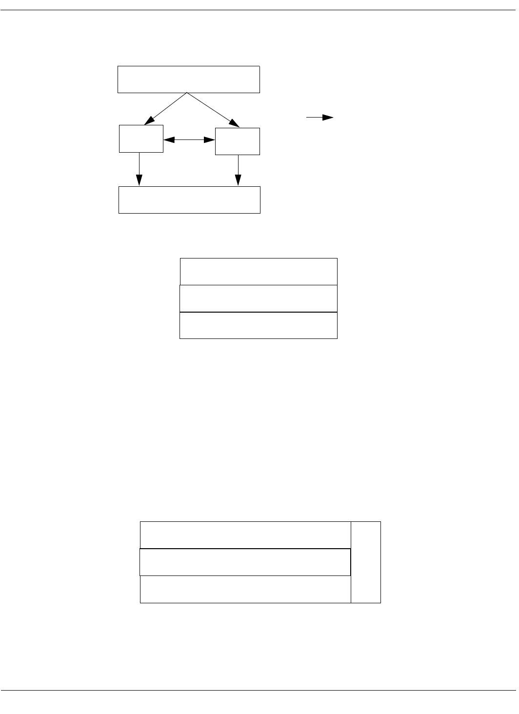
Documenting Software Architectures Clements, Bachmann, Bass, Garlan, Ivers, LIttle, Nord, Stafford
Copyright 2001 Addison Wesley, all rights reserved 92 Draft for review: Do not circulate without permission
a partial ordering of the elements. The cartoon below specifies that A is allowed to use B and C, which are in
turn allowed to use D
and each other.
From the strict point of view of layers, the diagram above is completely equivalent to this one:
where layer BC is the union of the contents of layers B and C. That’s because the “allowed to use” relation de-
picted by the two diagrams is the same. The decomposition of the middle layer into B and C brings additional
information to the diagram that has nothing to do with layering -- perhaps B and C have been developed by
separate teams, or represent separate modules, or will run on different processors.
Segmented layers, 3-D “toaster” models. Sometimes layers are shown as three dimensional models to em-
phasize that segments in one or more layers can be easily replaced or interchanged. Sometimes these are
called “toaster models” because the interchangeable pieces are shown in the shape and orientation of pieces
of bread dropped into slots as in a toaster. The figure below illustrates an example.
Layers with a sidecar. Many architectures called “layered” look something like the following:
This could mean one of two things. Either modules in D can use modules in A, B, or C. Or, modules in A, B, or
C can use modules in D. (Technically, the diagram might mean that both are true, although this would arguably
be a poor architecture.) It is incumbent upon the creator of the diagram to say which usage rules pertain. A
B
D
A
C
Key:
: allowed to use
D
A
BC
A
B
C
D

Chapter 2: Styles of the Module Viewtype
Copyright 2001 Addison Wesley, all rights reserved 93 Draft for review: Do not circulate without permission
variation like this only makes sense when the usage rules in the main stack are single-level: that is, when A can
use only B, and nothing below. Otherwise, D could simply be made the topmost (or bottom-most, depending on
the case) layer in the main stack, and the “sidecar” geometry would be completely unnecessary.
Contents: The modules that constitute a layer can be shown graphically if desired.
Interfaces: Sometimes the rectangles in a stack are shown with thick horizontal edges denoting the interface
to the layer. This is intended to convey the restriction that inter-layer usage only occurs via interface facilities,
and not directly to any layer’s “internals”. If a layer’s contents are depicted, as described above, then a lollipop
scheme such as the one in Figure 16 (which is reminiscent of Figure 4(b) on page 52) can be used to indicate
which modules’ interfaces make up the interface to the layer.
Figure 15: A 3-D or “toaster” model showing segmented layers.
(placeholder for real figure, which is tbd)
A
B
Key: informal notation
: allowed to use
B
: layer
: module (precise
type unspecified)

Documenting Software Architectures Clements, Bachmann, Bass, Garlan, Ivers, LIttle, Nord, Stafford
Copyright 2001 Addison Wesley, all rights reserved 94 Draft for review: Do not circulate without permission
Size and color: Sometimes layers are colored to denote which team is responsible for them or some other
distinguishing feature. Size is sometimes used to give a (vague) idea of the relative size of the modules consti-
tuting the various layers. If they carry meaning, size and color should be explained in the key accompanying
the layer diagram.
UML
Sadly, UML has no built-in primitive corresponding to a layer. However, simple (non-segmented) layers can be
represented in UML using
packages as shown in Figure 17. A package is a general-purpose mechanism for
organizing elements into groups. UML has pre-defined kinds of packages for systems and subsystems. We can
introduce an additional one for layers by defining it as a stereotype of package. A layer can be shown as a UML
package with the constraints that it modules together and that the dependency between packages is “allowed
to use”. We can designate a layer using the package notation with the stereotype name <<layer>> preceding
the name of the layer or introduce a new visual form, such as a shaded rectangle.
Layer L
M1 M2 M3
Figure 16: Notation to show which interfaces of which internal modules constitute the interface of
a layer.
Key: Informal notation
Layer
Module
Interface
Figure 17: A simple representation of layers in UML.
<<allowed to use>>
<<layer>> A
<<layer>> B

Chapter 2: Styles of the Module Viewtype
Copyright 2001 Addison Wesley, all rights reserved 95 Draft for review: Do not circulate without permission
The allowed-to-use relation can be represented as a stereotype of the UML access dependency, one of the
existing dependencies between packages. This dependency permits the elements of one package to reference
the elements of another package. More precisely:
• An element within a package is allowed to access other elements within the package.
• If a package accesses another package, then all elements defined with public visibility in the accessed
package are visible within the importing package.
• Access dependencies are not transitive. If package 1 can access package 2 and package 2 can access
package 3, it does not automatically follow that package 1 can access package 3.
If the “allowed-to-use” relation is loop-free, then one may wish to add the additional constraint that the defined
dependency is anti-symmetric. This stipulates that if A is allowed to use B, then we know that B is not allowed
to use A.
UML’s a mechanism to define the visibility of classes and packages can be used to define the interface to a
layer. The mechanism is to prefix the name of the package with a + for public (which is the default), # for pro-
tected, and - for not visible outside of the package. By appropriate tagging, then, we can define a layer’s inter-
face to be a subset of the interfaces of its elements.

Documenting Software Architectures Clements, Bachmann, Bass, Garlan, Ivers, LIttle, Nord, Stafford
Copyright 2001 Addison Wesley, all rights reserved 96 Draft for review: Do not circulate without permission
Figure 18 shows alternatives for representing segmented layers in UML.
Architects should be aware of the following problems when using UML packages to represent layers:
• Elements can only be owned by (that is, appear in) a single package. If an element needs to be a
member of a layer and a subsystem, for example, then packages cannot be used to represent both
(and recall that UML represents subsystems with a stereotyped package).
• It is not clear how to represent callbacks with UML. Callbacks are a common method of interaction
between modules in different layers; see “Upwardly Mobile Software.”
Relation of the Layered Style to Other Styles
Layer diagrams are often confused with other architectural styles when information orthogonal to the allowed-
to-use relation is introduced without conscious decision. In particular:
1.
Module decomposition. There is a tendency to regard layers as identical to modules in a decomposition
view. A layer may in fact be a module, but it is not necessarily always so. One reason this one-to-one map-
ping often fails is that modules are decomposed into other modules, whereas layers are not decomposed
into smaller layers. Segmented layers are often introduced to show mappings to modules. If a module
spans layers. colors or fill patterns are often used, as in the following:
<<layer>> C
<<layer>> A
<<layer>> B
<<segment>>
B1
<<segment>>
B1
<<segment>>
B1
<<layer>> C
<<layer>> A
<<layer>> B
<<segment>>
B1
<<segment>>
B1
<<segment>>
B1
Figure 18: Handling segmented layers in UML. If segments within a layer are allowed to use each other,
then dependency arrows must be added among the segments within the package for layer B as well.
Both of these alternatives have the property that they suggest that layer B is perhaps more than the
sum of its parts, and indeed some layers feature interfaces that are more than the union of their seg-
ments’ interfaces.

Chapter 2: Styles of the Module Viewtype
Copyright 2001 Addison Wesley, all rights reserved 97 Draft for review: Do not circulate without permission
The following example, once again borrowing from the A-7E architecture described previously, the
mapping between layers and modules is not one-to-one. In this architecture, the criteria for partitioning into
modules was the encapsulation of likely changes. The shading of the elements denotes the coarsest-grain
decomposition of the system into modules; that is, “Function driver” and “Shared services” are both
submodules of the Behavior-hiding module. Hence, in this system, layers correspond to parts of highest-
level modules. It’s also easy to imagine a case where a module constitutes a part of a layer.
2.
Tiers. Layers are very often confused with the tiers in an n-tier client-server architecture, such as shown
in the following figure:
Function driver
Shared services
Data
banker
Physical
models
Filter
behaviors
Device interfaces
Application data types
Software
utilities
Extended computer
Behavior-hiding module
Software decision hiding module
Hardware hiding module
Key:
Presentation layer or
Graphical user interface
Business logic
Data server

Documenting Software Architectures Clements, Bachmann, Bass, Garlan, Ivers, LIttle, Nord, Stafford
Copyright 2001 Addison Wesley, all rights reserved 98 Draft for review: Do not circulate without permission
Despite the fact that this looks like a layer diagram, despite the fact that the topmost element even uses
the “L”-word in its name, and despite the fact that many careless authors use “layers” and “tiers
interchangeably, diagrams such as this express concerns very different from layers. Allocation to machines
in a distributed environment, data flow among elements, and the presence and utilization of communication
channels all tend to be expressed in tier pictures, and these are indiscernible in layer diagrams. And notice
the two-way arrows. Whatever relations are being expressed here (and as always, a key should tell us),
they’re bi-directional (symmetric) and we know that’s bad news in a layer diagram.
Further, assignment of a module to one of these elements is based on run-time efficiency of some sort:
locality of processing, maintaining the ability to do useful work in case of network or server failure, not
overloading the server, wise utilization of network bandwidth, etc.
Layers are not tiers, which in fact belong in a hybrid view combining styles in the component-and-connector
and allocation viewtypes. Even in an architecture in which there is a one-to-one correspondence between
layers and tiers, you should still plan on documenting them separately as they serve very different
concerns.
For more information...
"Examples of combined views" on page 191 treats the classic n-tier client-server archi-
tecture as an example of a hybrid style.
3. Module “uses” style. Because layers express the “allowed-to-use” relation there is a close correspon-
dence to the uses style. It is likely, but not always the case, that if an architect chooses to include one in
the documentation suite then the other is likely to be included as well. Of course, no uses relation is allowed
to violate the allowed-to-use relation. If incremental development or the fielding of subsets is a goal, then
the architect will begin with a broad allowed-to-use specification to guide the developers during implemen-
tation. That specification should permit any subset of interest to built efficiently and without having to in-
clude scores of superfluous programs. Later, actual uses can be documented.
4.
Subsystems. Layers cross conceptual paths with the concept of subsystem, as we saw in “Coming to
Terms: ‘Subsystem’“ on page 59.) The air traffic control system shown there was depicted using a seg-
mented layers diagram; it is reproduced below for convenience.
A subsystem in this context consists of a segment from the top layer, plus any segments of any lower layers
it’s allowed to use.
Example of the Layered Style
tbd
Position
display
Monitoring
Recording &
playback
Collision
avoidance
Subsystem layer
Application support layer
Display generation
Simulation
Workstation scheduler
Network communications
Operating system
Communications layer
Platform layer

Chapter 2: Styles of the Module Viewtype
Copyright 2001 Addison Wesley, all rights reserved 99 Draft for review: Do not circulate without permission
2.5 Glossary
• application program interface (API) - A set of routines (functions, procedures,
methods) and protocols. An API defines the boundary between layers.
• interface - An interface defines the boundary between modules. An interface
defines the services provided and required by each module.
• layer - A virtual machine with a set of capabilities/services. These services can only be accessed
through a layer’s interface.
• layer structure - a collection of layers where each layer provides services to the layer above and is
allowed to use the services of the layer below.
• uses - procedure A is said to use procedure B if a correctly functioning procedure B must be present
in order for procedure
A to meet its requirements.
• virtual machine - a collection of modules that together provides a cohesive set of services that other
modules can utilize without knowing how those services are implemented.
• bridging, layer bridging - an exception to the stated allowed-to-use relation indicated by the layers.
Bridging usually occurs when a high layer uses a low layer directly without going through intermediate
layers.
• strict layering - layers are allowed to use only the immediately adjacent lower layer.
2.6 Summary checklist
tbd
2.7 For Further Reading
To be added
2.8 Discussion Questions
1. Can you think of a system that is not layered, that is, that cannot be described using a layered
view? If a system is not layered, what would this say about its allowed-to-use relation?
2. How does a UML class diagram relate to the styles given in this chapter? Does it show decomposition,
uses, generalization, or some combination? (Hint: We’ll discuss this in some detail in the section in Chapter
13 ("Related Work") dealing with the Rational Unified Process.)
3. We consciously chose the term “generalization” to avoid the multiple meanings that the term “inheritance”
has acquired. Find two or three of these meanings, compare them, and discuss how they are both a kind
of generalization. (Hint: you may wish to consult books by Booch and Rumbaugh, respectively.)
?

Documenting Software Architectures Clements, Bachmann, Bass, Garlan, Ivers, LIttle, Nord, Stafford
Copyright 2001 Addison Wesley, all rights reserved 100 Draft for review: Do not circulate without permission
4. Suppose that a portion of a system is generated with, for example, a user interface builder tool. Using one
or more views in the module viewtype, how would you show the tool, the input to the tool (i.e., the user
interface specification) and the output from the tool?
2.9 References [move to back of book]
1. [BJR98] Booch, Jacobson, and Rumbaugh. The Unified Modeling Language User Guide. Addison-Wesley
Longman, Inc., October 1998.
2. Buschmann, Meunier, Rohnert, Sommerlad, and Stal.
A System of Patterns: Pattern Oriented Software Ar-
chitecture
, John Wiley & Sons, 1996.
3. Hofmeister, Nord, and Soni.
Applied Software Architecture, Addison-Wesley, 2000.
4. M. Shaw and D. Garlan.
Software Architecture: Perspectives on an Emerging Discipline, Prentice Hall, Up-
per Saddle River NJ, 1996.
5. [BCK98]: L. Bass, P. Clements, R, Kazman:
Software Architecture in Practice, Addison Wesley Longman,
1998.
6. [PW76] D. L. Parnas, H. Wurges, “Response to Undesired Events in Software Systems,”
Proceedings of
the Second International Conference on Software Engineering,
October 1976, pp. 437-446.
7. [P79]: Parnas, D. L.; “Designing Software for Ease of Extension and Contraction,”
IEEE Transactions on
Software Engineering
, vol. SE-5, no. 2, pp. 128-137.
8. [P74] Parnas, D. L. “On a ‘Buzzword’: ‘Hierarchical Structure“,
Proc. IFIP Congress, 74:336-390, 1974.
9. [K95] Kruchten, P., “The 4+1 View Model of Architecture,”
IEEE Software, 12(6):42-50,1995.
10. [GHJV95] E. Gamma, R. Helm, R. Johnson, and J. Vlissides.;
Design Patterns, Elements of Reusable Ob-
ject-Oriented Software
, Addison-Wesley, 1995.
11. [SNH95] Soni, D., R. Nord, C. Hofmeister, “Software Architecture in Industrial Applications,” Proceedings,
International Conference on Software Engineering, April 1995, pp. 196-210.
12. [SAAM] http://www.sei.cmu.edu/architecture/sw_architecture.html
13. [ATAM] http://www.sei.cmu.edu/architecture/sw_architecture.html
14. [S90] Smith, C.U.,
Performance Engineering of Software Systems, The SEI Series in Software Engineer-
ing, Addison-Wesley Publishing Corp., 1990.
15. [PW92] Perry, D.E., and Wolf, A.L., “Foundations for the Study of Software Architecture,” Software Engi-
neering Notes, ACM SIGSOFT, vol. 17, no. 4, October 1992, pp. 40-52.
16. [GS93] Garlan, D., and Shaw, M.; “An introduction to software architecture,” in
Advances in Software En-
gineering and Knowledge Engineering,
vol. I, World Scientific Publishing Company,1993.
17. [GP95] Garlan, David; Perry, Dewayne, Introduction to the Special Issue on Software Architecture,
IEEE
Transactions on Software Engineering,
Vol 21, No. 4, April 1995
[end]

Chapter 3: The Component-and-Connector Viewtype
Copyright 2001 Addison Wesley, all rights reserved 101 Draft for review: Do not circulate without permission
Chapter 3: The Component-and-Connector
Viewtype
3.1 Introduction
Component-and-connector (C&C) views define models consisting of elements that have some run-time pres-
ence, such as processes, objects, clients, servers, and data stores. Additionally, component-and-connector
models include as elements the pathways of interaction, such as communication links and protocols, informa-
tion flows, and access to shared storage. Often these interactions will be carried out using complex infrastruc-
ture, such as middleware frameworks, distributed communication channels, and process schedulers.
A C&C view provides a picture of run-time entities in action. Within such a view there may be many instances
of the same type of component. For example, you might have a Kalman Filter component type that is instanti-
ated many times within the same view. Drawing on an analogy from object-oriented systems, execution-based
views are similar to object (or collaboration) diagrams, as opposed to class diagrams, which would define the
types of the elements.
The interaction mechanism (that is, the connectors) in C&C views are treated as first class design elements:
choosing the appropriate forms of interaction between computational elements is a critical aspect of an archi-
tect’s task. These interactions may represent complex forms of communication. For example, a connection be-
tween a client component and a server component might represent a complex protocol of communication,
supported by sophisticated run-time infrastructure. Other interactions might represent multi-party forms of com-
munication, such as event broadcast, or n-way data synchronization.
C&C views are commonly used in practice, and indeed, box-and-line diagrams depicting these views are often
the graphical medium of choice as a principal first-look explanation of the architecture of a system. But, in prac-
tice, C&C views can be misleading, ambiguous, and inconsistent. Some of these problems follow from the usual
pitfalls of visual documentation that are equally applicable to any of the graphical viewtypes discussed in this
book. But other problems are more specifically related to the use of components and connectors to portray a
system’s execution structure. In this chapter we bring some clarity to the picture by describing guidelines for
documenting C&C views, as well as highlight common pitfalls.
Let us begin with an informal examination of the C&C viewtype by means of a simple example. Figure 19 illus-
trates a primary presentation of a C&C view as one might encounter it in a typical description of a system’s run-
time architecture.
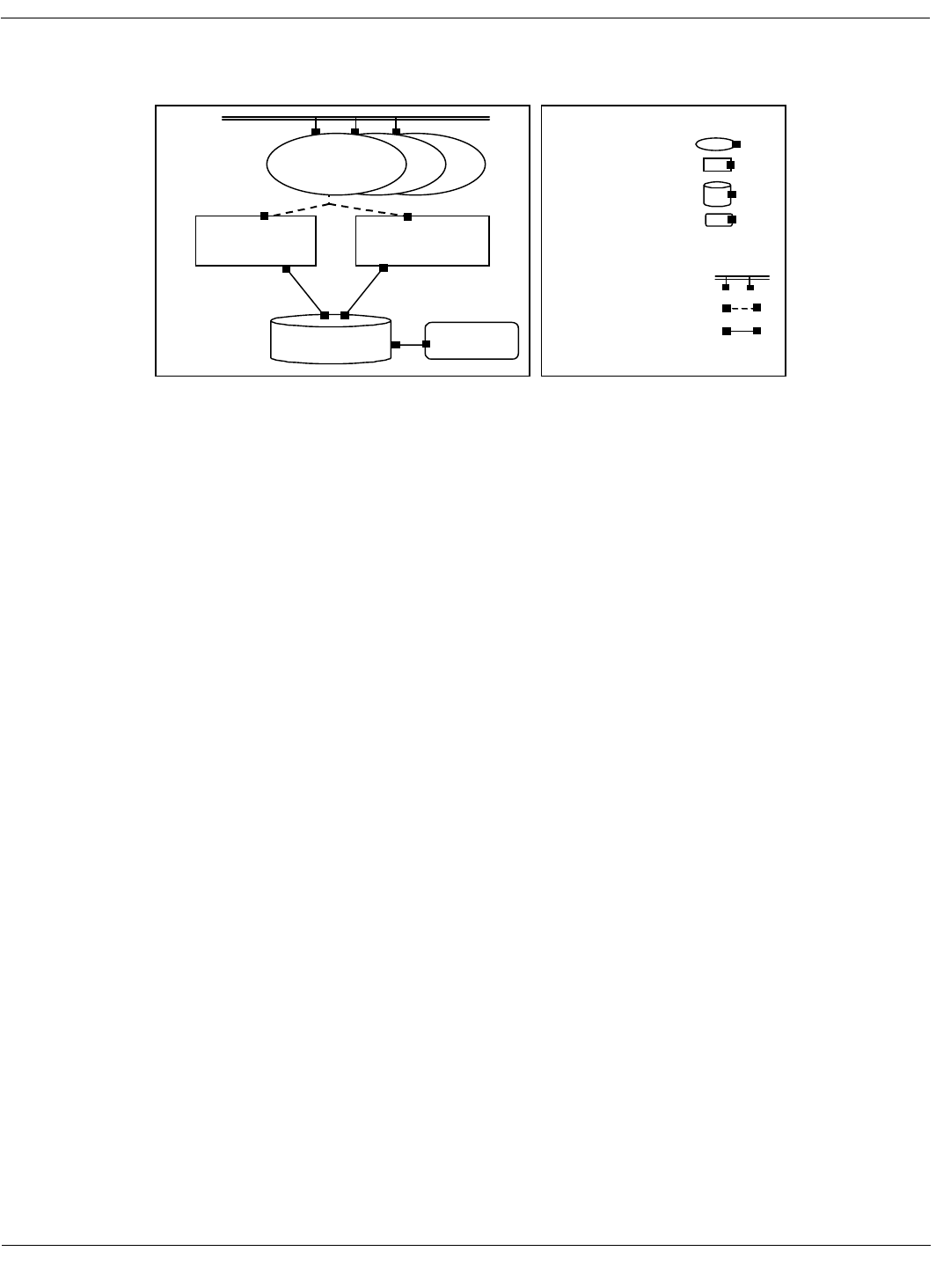
Documenting Software Architectures Clements, Bachmann, Bass, Garlan, Ivers, LIttle, Nord, Stafford
Copyright 2001 Addison Wesley, all rights reserved 102 Draft for review: Do not circulate without permission
What is this cartoon, backed up by its supporting documentation, attempting to convey? Most obviously, we are
being shown a bird’s-eye view of the system as it might appear during run time. The system contains a shared
repository of customer accounts (
Account DB) accessed by two servers and an administrative component. A
set of client tellers can interact with the account repository servers, embodying a client-sever style. These client
components communicate among themselves through a publish-subscribe connector. The purpose of the two
servers (we learn from the supporting documentation) is to enhance reliability: if the main server goes down,
the backup can take over. Finally, there is a component that allows an administrator to access, and presumably
maintain, the shared data store.
There are three types of connectors shown in this cartoon, each representing a different form of interaction
among the connected parts. The client-server connector allows a set of concurrent clients to retrieve data syn-
chronously via service requests and supports transparent failover to a backup server. The database access
connector supports authenticated administrative access for monitoring and maintaining the database. The pub-
lish-subscribe connector supports asynchronous announcement and notification of events.
Each of these connectors represents a complex form of interaction, and will likely require non-trivial implemen-
tation mechanisms. For example, the client-server connector type represents a protocol of interaction that pre-
scribes things like how clients initiate a client-server session, constraints on ordering of requests, how/when
failover is achieved, and how sessions are terminated. Its implementation will probably involve run-time mech-
anisms that handle such things as detecting when a server has gone down, queuing client requests, handling
attachment and detachment of clients, etc. Note also that connectors need not be binary: two of the three con-
nector types in this example can involve more than two participants.
It may also be possible to carry out both qualitative and quantitative analyses of system properties such as per-
formance, reliability, and security. For instance, the design decision that causes the administrative interface to
be the only way to change the database schema would have a positive impact on the security of the system.
Figure 19: A bird’s-eye-view of the system as it might appear during run time. The system contains a
shared repository that is accessed by servers and an administrative component. A set of client tellers
can interact with the account repository servers and communicate among themselves through a pub-
lish-subscribe connector.
Account
Server-main
Account
Server-
b
ackup
Admin
Component types:
Client
Server
Database
DB Appl
Connector types:
Publish-subscribe
Client-server
Database access
Account DB
Client Client
Client
Teller 1
Key

Chapter 3: The Component-and-Connector Viewtype
Copyright 2001 Addison Wesley, all rights reserved 103 Draft for review: Do not circulate without permission
But it also might have implications on administratability or concurrency (e.g., does the use of the administrative
interface lock out the servers?). Similarly, by knowing properties about the reliability of the individual servers,
one might be able to produce numeric estimates of the overall reliability of the system using some form of reli-
ability analysis.
Some things to notice about this figure are:
• It acts as a key to the associated supporting documentation (not shown).
• It is simple enough to comprehend in a single bite.
• It is explicit about its vocabulary of component and connector types.
• It provides a key to discussions about the number and kind of interfaces on its components and
connectors.
• It uses abstractions for its components and also for its connectors that concentrate on application
functionality rather than implementation mechanism.
The documentation that contained the graphic shown in this figure would probably elaborate the elements
shown. Supporting documentation, discussed in Section 10.1 ("Documenting a view"), should explain how
Ac-
count Server-backup
provides reliability for the total system. An expanded C&C figure (not shown) might
focus just on the main account server, its backup, and the client server connection.
3.2 Elements, Relations, and Properties of the C&C Viewtype
We now define the elements, relations, and properties that can appear in views of this type. As we describe the
constituents of a C&C viewtype, we also list guidelines about effective use of them in describing software ar-
chitecture.

Documenting Software Architectures Clements, Bachmann, Bass, Garlan, Ivers, LIttle, Nord, Stafford
Copyright 2001 Addison Wesley, all rights reserved 104 Draft for review: Do not circulate without permission
Elements
The elements of a C&C viewtype are components and connectors. Each of the elements in a C&C view of a
system has a run-time manifestation as an entity that consumes execution resources, and contributes to the
execution behavior of that system. The relations of a C&C view associate components with connectors to form
a graph that represents a run-time system configuration.
These run-time entities are instances of component and connector
types. The available types are either defined
by choosing a specific architectural style that prescribes a set of C&C building blocks (see Chapter 4) or they
may be custom defined. In either case, the types are chosen because there is significant commonality among
several components or connectors in the architecture. Defining or using a set of component and connector
types provides a means for capturing this commonality, provides a specialized design vocabulary targeted to
specific domains, and introduces constraints on how that vocabulary is used.
Table 8: Summary of the C&C Viewtype
Elements • components: principal processing units and data stores
• connectors: interaction mechanisms
Relations
• attachments: define system topology by indicating which
component ports are associated with which connector roles
Proper-
ties of
elements
component
• name -- component name should hint at its functionality
• type -- defines general functionality, number and types of ports,
required properties
• ports -- a list of ports and their types and/or properties
• other properties -- depend on type of component, but include things
such as performance and reliability values.
connector
• name -- connector name should hint at the nature of its interactions
• type -- defines nature of interaction, number and types of roles,
required properties
• roles -- a list of roles and their properties
• other properties -- depend on the type of connector, but include
things such as protocol of interaction, and performance values
Topology Ports may only be attached to roles

Chapter 3: The Component-and-Connector Viewtype
Copyright 2001 Addison Wesley, all rights reserved 105 Draft for review: Do not circulate without permission
Components
Definition
Components represent the principal computational elements and data stores that
execute in a system.
Each component in a C&C view has a name. The name should provide a hint about the intended function of
the component. More importantly, it allows one to relate the graphical element with supporting documentation.
Each component in a C&C view has a type.
Examples of generic component types are clients, servers, filters,
objects, and databases. Other component types might be more domain-specific, such as a controller compo-
nent type (used in a process control architecture), or a sensor component type used in some avionics applica-
tion. A component type is defined in terms of its general computational nature and its form. For example, if a
component has the type “filter,” the component processes input streams on its input channel interfaces, and
produces output on its output channel interfaces. Similarly, if a component has the type “server,” it must have
an interface providing a set of service calls that clients may invoke, and its main computational role is to service
those requests. A component type description includes the kinds and number of interfaces it supports, and re-
quired properties.
The set of component types that contribute to a C&C view should be explicitly enumerated and defined. This
may be done in a style guide for the style that you’re using, if such a guide exists. Or, it may be done by defining
the type in the properties of the component. For instance, the intended semantics of component types such as
“filter” or “server” would need to be defined.
For more information...
Chapter 2 ("Styles of the Module Viewtype"), Chapter 4 ("Styles of the C&C Viewtype"),
and Chapter 6 ("Styles of the Allocation Viewtype") present the styles we cover in this
book, one per section. Each of those sections serves as an example of a style guide.
Section 7.5 ("Creating and Documenting a New Style") explains how to devise, and doc-
ument, a style of your own.
In some cases the set of types used in a C&C view are inherited by using a particular C&C architectural style.
For example, a C&C view defined in the Pipe-Filter style will make use of pipe connector types and filter com-
ponent types, as prescribed by that style.
For more information...
The pipe and filter C&C style is discussed in Section 4.1
Although components have types, a C&C view contains component instances; that is, no component types
should appear in the view itself. There may be many components of the same type in a C&C view. For example,
there may be many instances of the same server type in a view. In cases where the designer does not want to

Documenting Software Architectures Clements, Bachmann, Bass, Garlan, Ivers, LIttle, Nord, Stafford
Copyright 2001 Addison Wesley, all rights reserved 106 Draft for review: Do not circulate without permission
commit to a particular number of some replicated component, or that number changes dynamically (as a sys-
tem operates) it is possible to indicate a variable number of some component type. This can be done in a num-
ber of ways. However the meaning of any replication should be clearly documented. In particular, the
documentation should be clear about whether the variability is resolved at design time, system configura-
tion/deployment time, or run time.
For more information...
Conventions for showing replication are discussed in Section 7.4 ("Documenting Vari-
ability and Dynamism").
Components have interfaces. Given the run-time nature of C&C views, an interface represents a specific point
of (potential) interaction of a component with its environment. These are referred to as
ports to emphasize their
run-time nature and to distinguish them from the interfaces of other kinds of architectural design elements, such
as classes.
A component’s ports should be explicitly documented. When documenting a component in a C&C view it is im-
portant to be clear about the number and type of the component’s ports. Note the use of plural: a component
may have many ports of the same or different types. For example, in the example of Figure 19 the database
had two server-oriented ports, as well as an administrative port.
Advice
To illustrate how one should not document a C&C view, consider the “architecture” in Figure 20.
|| END SIDEBAR/CALLOUT advice how not to document
Connectors
The other kinds of elements in a C&C viewtype are connectors.
Class A
Client 1
Server
Figure 20: How not to document a C&C view. This diagram has poor visual discrimination between
elements, no key, a mixture of code-based and run-time elements, no explicit indication of interfaces,
and anonymous components

Chapter 3: The Component-and-Connector Viewtype
Copyright 2001 Addison Wesley, all rights reserved 107 Draft for review: Do not circulate without permission
Definition
A connector represents a run-time pathway of interaction between two or more
components.
Simple kinds of connectors include procedure call (e.g., between two objects or a client and server), asynchro-
nous messages, event multicast (e.g., between a set of components that communicate among each other using
publish-subscribe), and pipes (e.g., that represent asynchronous, order-preserving data streams). But connec-
tors often represent much more complex forms of interaction, such as a transaction-oriented communication
channel between a database server and client. These more complex forms of interaction may in turn be de-
composed into collections of components and connectors that typically describe the run-time infrastructure that
makes the more abstract form of interaction possible. For example, a decomposition of the “fail-over” client-
server connector of Figure 6-1 would probably include components that are responsible for buffering client re-
quests, determining when a server has gone, and rerouting requests. (See also sidebar “Are Connectors Really
Necessary?”.)
Observation
SIDEBAR: Are connectors really necessary?
We have argued that connectors should be first class design elements for documenting execution-based
views: they can represent complex abstractions; they have types; they have interfaces (roles); they re-
quire detailed semantic documentation.
But couldn’t one simply use a mediating component wherever a complex connector arises? For example,
as shown below, the complex connector Conn-1 gets replaced by the component Comp-1.
In other words, are connectors really needed? The answer is emphatically “Yes!” Connectors are needed.
Here’s why.
First, shifting the description as illustrated above begs the question, since the new depiction also has con-
nectors. So we haven’t “gotten rid” of connectors.
“Oh, but these are much simpler connectors,” you say. Maybe. But even simple interactions such as mes-
sage sending or procedure call become complex in their own right in most distributed settings. Moreover,
why should one think that the particular choice of simple connector for one system will be the same for
another. In one case a simple connector might be a message send. In another it might be a procedure
Conn-1 Comp-1
C1 C2 C1 C2

Documenting Software Architectures Clements, Bachmann, Bass, Garlan, Ivers, LIttle, Nord, Stafford
Copyright 2001 Addison Wesley, all rights reserved 108 Draft for review: Do not circulate without permission
call. In another, it might be an event announcement. Since there is no universal “simplest” connector, we
will always need to be clear about exactly what we are modeling when we describe an interaction.
The second reason that we need rich connector abstractions is that avoidance of complex connectors can
significantly clutter an architectural model with unnecessary detail. Few would argue that the right hand
diagram above is more perspicuous. Magnify this many times in a more complex diagram, and it becomes
obvious that clarity is served by using connectors to encapsulate details of interaction
The third reason is that more clearly indicates the architect’s intent. When components are used to rep-
resent complex connectors, it is often no longer clear which components in a diagram are essential to the
application-specific computation, and which are part of the mediating infrastructure.
The fourth reason is that connectors are rarely realizable as a single mediating component. While most
connector mechanisms do involve run-time infrastructure that carries out the communication, that is not
the only thing that is involved. In addition, a connector implementation also requires initialization and fi-
nalization code, special treatment in the components that use the connector (e.g., using certain kinds of
libraries), global operating system settings (such as registry entries), and others. (For a more thorough
discussion of connector mechanisms see [cite Shaw Unicon Connectors].
The fifth reason is that rich connectors support rich reasoning. For example, reasoning about a data flow
system is greatly enhanced if the connectors are pipes, rather than procedure calls or some other mech-
anism. This is because, there are well-known calculi for analyzing dataflow graphs. Additionally, allowing
complex connectors provides a single home where one can talk about the semantics. For example in the
figure above, I could attach a single protocol description to the complex connector. In contrast, the right
hand model would require me to combine the descriptions of two connectors and a component to figure
out what is going on.
-- DG
|| END SIDEBAR/CALLOUT “are components really necessary?”
As with components, each connector in a C&C view should have a type,
which defines the nature of the inter-
action supported by the connector. The type also makes clear what form the connector can take, such as how
many components can be involved in its interaction, the kinds and number of interfaces it supports, and re-
quired properties. Often the “computational nature” of a component is best described as a protocol.
The set of connector types that contribute to a particular C&C view should, like component types, be explained
by referring to the appropriate style guide that enumerates and defines them. If the view does not correspond
to a style for which a guide exists, then the connector types may be defined in the property list for the connec-
tors.
For more information...
Style guides are described in Section 7.5 ("Creating and Documenting a New Style"). A
standard organization for a style guide, used in the chapters of this book that explain
styles, is given in “Style Guides” on page 38.
Part of the description of a connector type should be a characterization of the kind and number of “roles” that
instances of that type can have. A connector’s roles can be thought of as interfaces of the connector, insofar
as they define the ways in which the connector may be used by components to carry out interactions. For ex-
ample a client-server connector might have “invokes-services” and a “provides-services” role. A pipe might
have a “writer” and a “reader” role. A publish-subscribe connector might have many “publisher” and “subscriber”
roles. A role typically defined the expectations of a participation in the interaction. For example, an “invokes-

Chapter 3: The Component-and-Connector Viewtype
Copyright 2001 Addison Wesley, all rights reserved 109 Draft for review: Do not circulate without permission
services” role might require that the service invoker initialize the connection before issuing any service re-
quests.
Background
Choosing connector abstractions
Picking appropriate connector abstractions is often one of the most difficult jobs of producing effective ar-
chitectural documentation using the C&C viewtype. If the connector abstractions are too low-level, then
the view will become cluttered both with connectors and with components that are actually logically part
of the connector mechanism (see below). If the connector abstractions are too high-level, it may be diffi-
cult to map from the C&C views to more implementation-oriented views. While deciding how abstract to
make connectors is a matter of taste and the needs of architectural analysis, documentation that one finds
for today’s systems tends to err on the side of being too low-level.
To illustrate alternative choices in abstraction and representation with respect to connectors, consider the
two forms of a simple publish-subscribe system shown in Figure 21. The first version shows five compo-
nents communicating through an event “bus.” The second version shows the same five components, but
this time communicating with the assistance of a dispatcher component, which is responsible for distrib-
uting events via procedure calls to the other components. Which is better? The first is more abstract, since
the connector encapsulates the underlying mechanism. Abstraction is good since it allows alternative im-
plementations (such as multiple dispatchers, or even point-to-point distribution of events between compo-
nents) and it simplifies the diagram. The first version also more clearly indicates the n-ary nature of the
interaction: events announced by one component may be delivered to multiple subscribers. On the other
hand, for some purposes it may be important to show the dispatcher. For example, to calculate event-
throughput it might be necessary to reason about the properties of some centralized dispatch mechanism
that carries out the communication. Version 2 could be an implementation refinement of Version 1; which
mechanism you choose depends on the context.
Because picking connector abstractions is a difficult job, it is worth listing some guidelines to keep in mind.
C1 C2
C3 C4 C5
Version 1
C1 C2
C3 C4 C5
Version 2
Event
Dispatcher
Figure 21: Two potential versions of a publish-subscribe system. In Version 1 all communica-
tion takes place over an event “bus,” while in Version 2 communication is occurs with the as-
sistance of a dispatcher component. [notation key to be added]
Documenting Software Architectures Clements, Bachmann, Bass, Garlan, Ivers, LIttle, Nord, Stafford
Copyright 2001 Addison Wesley, all rights reserved 110 Draft for review: Do not circulate without permission
Advice
Connectors need not be binary. As indicated in the examples above, connectors
may have more than two roles. Even if the connector is ultimately implemented us-
ing binary connectors (e.g., procedure call), it can be useful to adopt n-ary connec-
tor representations at an abstract architectural level.
Advice
If a component’s primary purpose is to mediate interaction between a set of com-
ponents, consider representing it as a connector. Such components are often best
modeled as part of the communication infrastructure. This was illustrated above.
Advice
Connectors can (and often should) represent complex forms of interaction. Even a
semantically simple procedure call can be complex when carried out in a distribut-
ed setting, involving run-time protocols for time-outs, error handling, locating the
service provider (e.g., as provided by a CORBA implementation).
Advice
Connectors embody a protocol of interaction. When two or more components in-
teract they must obey conventions about order of interactions, locus of control,
handling of error conditions and time-outs. When providing a detailed description
of a connector, the documentation should attempt to capture this detail.
|| END SIDEBAR/CALLOUT
Relations
The relation of the C&C viewtype is attachment. Attachments indicate which connectors are attached to which
components, thereby defining a system as a graph of components and connectors. Formally this is done by
associating component ports with connector roles: a component port, p, is attached to a connector role, r, if the
component interacts over the connector using the interface described by p, and conforming to the expectations
described by r.
Use the following guidelines when defining a graph of components and connectors using attachments:
Advice
Be clear which style you are using, by referring to an appropriate style guide.
Chapter 3: The Component-and-Connector Viewtype
Copyright 2001 Addison Wesley, all rights reserved 111 Draft for review: Do not circulate without permission
Advice
Always attach a connector to a particular port of a component.
Advice
If it is not clear that it is valid to attach a given port with a given role, provide a jus-
tification in the rationale section for the view. For example, if an “invokes-services”
role requires the service invoker to initialize the connection before issuing any ser-
vice requests, you should explain why the port obeys this rule. In many cases, the
justification can be done by appealing to the use of standard interfaces and proto-
cols. For example, a client port might be argued to be consistent with a role of an
http client-server connector simply by arguing that the port respects the http pro-
tocol. In other cases, however, a more detailed and connector-specific argument
may be needed.>The point I was making is based on the observation that are lots of
Advice
Make clear which ports are used to connect the system to its external environment.
For example if an external user interface, outside the system, will be providing in-
put to some components, then those components should have ports for that exter-
nal connection. Put another way, every interface that appears in a system’s context
diagram should also appear in (at least) the top-level C&C view of the system.

Documenting Software Architectures Clements, Bachmann, Bass, Garlan, Ivers, LIttle, Nord, Stafford
Copyright 2001 Addison Wesley, all rights reserved 112 Draft for review: Do not circulate without permission
Advice
To illustrate what not to do, Figure 22 presents an example of a poorly documented C&C view.
|| END SIDEBAR/CALLOUT advice how not to document a connector
Properties
A particular element may have a number of different kinds of associated properties including the name, type,
and ports or roles of the element.
Other properties are possible and they should be chosen to support the usage intended for the particular com-
ponent-and-connector view. For example, different properties might be chosen depending on whether the view
is to be used as a basis for construction, analysis, or communication, as outlined below.
Here are some examples of typical properties and their uses:
• Reliability: What is the likelihood of failure for a given component or connector? This might be used to
help determine overall system reliability.
• Performance: What kinds of response time will the component provide and under what loads? What
kinds of latencies and throughputs can be expected for a given connector? This can be used (with other
properties) to determine system properties such as latencies, throughput, and buffering needs.
• Resource requirements: What are the processing and storage needs of a component or connector?
This can be used to determine if a proposed hardware configuration will be adequate.
• Functionality: What functions does an element perform? This can be used to reason about overall
computation performed by a system.
UI
Server 1
Server 2
Corba
Communication Substrate
API
Figure 22: A poorly documented C&C view. There is no key; it portrays an API as a
component; it uses different shapes for same type of element; it uses the same shape
for different types of elements; it confuses context with system to be built; its use of
arrows is not explained; it has no explicit interface points.

Chapter 3: The Component-and-Connector Viewtype
Copyright 2001 Addison Wesley, all rights reserved 113 Draft for review: Do not circulate without permission
• Protocols: What patterns of events or actions can take place for an interaction represented by a
component or connector? Protocols can be used to determine whether a particular interaction can
deadlock, whether specific components can legally participate in a given interaction, what are the
ordering constraints on an interaction, and how errors are handled.
• Security: Does a component or connector enforce or provide security features, such as encryption,
audit trails, or authentication? This can be used to determine system security vulnerabilities.
3.3 What the C&C Viewtype Is For, and What It’s Not For
The C&C viewtype is used to reason about run-time system quality attributes, such as performance, reliability,
availability. In particular, a well documented view will allow architects to predict overall system properties, given
estimates or measurements of properties of the individual elements and interactions. For example, to determine
whether the overall system can meet its real-time scheduling requirements you must usually know the cycle
time of each process in a process-oriented view. Similarly, knowing the reliability of individual elements and
communication channels supports an architect when estimating or calculating overall system reliability. In some
cases this kind of reasoning is supported by formal, analytical models and tools. In others, it is achieved by
judicious use of rules of thumb and past experience.
C&C views allow one to answer questions such as:
• What are the system’s principal executing components and how do they interact?
• What are the major shared data stores?
• Which parts of the system are replicated, and how many times?
• How does data progress through a system as it executes?
• What protocols of interaction are used by communicating entities?
• What parts of the system run in parallel?
• How can the system’s structure change as it executes?
C&C views are not appropriate for representing design elements that do not have a run-time presence. For ex-
ample, a class is not a component. A good rule of thumb is that if it doesn’t make sense to characterize the
interface(s) of an element, it probably isn’t a component (although the inverse is clearly not necessarily true –
there are many things with interfaces that are not components).
Background
Projections
Two views that have long been used to document software systems -- so long, in fact, that we might con-
sider them archaic today -- are the data flow and control flow views. These show how data and control,
respectively, flow around a system during execution, and each is useful for performing a particular kind of
analysis. Understanding control flow, for instance, helps programmers track down the source of a bug.

Documenting Software Architectures Clements, Bachmann, Bass, Garlan, Ivers, LIttle, Nord, Stafford
Copyright 2001 Addison Wesley, all rights reserved 114 Draft for review: Do not circulate without permission
Both of these are examples of projections of a C&C view. Each highlights certain aspects of a view in order
to simplify discussion or to analyze specific properties of the view. A data flow projection can be derived
by examining the connector protocols to determine in which direction data can flow between components.
One can then project a dataflow view from a C&C view by replacing connectors with one- or two-headed
arrows indicating flow of data, and eliminating connectors that have no data component. A similar ap-
proach works for control flow. Of course, you need to be clear what you mean by control flow and how
that relation is derived from knowledge about the connectors in a C&C view.)
When attempting to extract a dataflow or control flow relation from a more general connector there are a
number of pitfalls to be aware of. For instance, consider a very simple, but typical, situation illustrated in
Figure 23, showing two components C1 and C2, that interact via a procedure call connector, p. Assume
that procedure p takes some number of arguments and returns a value. How would we project a dataflow
relation? In particular, which way should the arrow go? Since C1 passes data to C2 in the form of proce-
dure parameters one might argue data flows from C1 to C2. But since the C2 returns a value perhaps it
should go the other way. Or should it go both ways?
The same confusions apply to control flow. C1 invokes C2, so one might argue that control flows form C1
to C2. But C1 must block when C2 is performing its invoked operation, suggesting that C2 controls C1
during that period of invocation. And, of course, when C2 is finished, it returns control to C1.
And this is one of the most simple forms of interaction! Most connectors will be more sophisticated, per-
haps involving multiple procedure calls, rules for handling exceptions and time-outs, and callbacks.
The main conclusions to draw are twofold. First, when creating a dataflow or control flow projection be
explicit about the semantic criteria being used. Second, recognize that dataflow and control flow projec-
tions are at best approximations to the connectors, which define the actual interactions between compo-
nents.
For more information...
Data and control flow views are discussed in Section 13.7.
|| END SIDEBAR/CALLOUT Projections
3.4 Notations for the C&C Viewtype
Notations for the C&C Viewtype are discussed in Chapter 4 ("Styles of the C&C Viewtype").
3.5 Relation of Views in the C&C Viewtype with Views in Other
C1 C2
p
Figure 23: A component-and-connector fragment showing that C1 calls C2. To turn this
into a data flow or control flow projection, which way should the respective arrows
point? [key to be added]

Chapter 3: The Component-and-Connector Viewtype
Copyright 2001 Addison Wesley, all rights reserved 115 Draft for review: Do not circulate without permission
Viewtypes
The most interesting relationship concerning C&C views is how they map to a system’s module views. The re-
lationship between a system’s C&C views and its module views may be complex. The same code module might
be executed by many of the elements of a C&C view. Conversely, a single component of a C&C view might
execute code defined by many modules. Similarly, a C&C component might have many points of interaction
with its environment, each defined by the same module interface.
3.6 Glossary
• tbd
3.7 Summary checklist
tbd
3.8 For Further Reading
tbd
Here in the early days of what some are calling the age of component-based software engineering, we are
awash in stories where the architect thought he or she could plug two components together with a connector,
only to find out that the component didn’t implement the right protocol, or was otherwise badly matched with
the expectations of that connector. This is why we prescribe writing a justification where the match-up is less
than obvious. For a thoughtful treatment of element mismatch, see [garlan et al. mismatch paper].
Shaw, Garlan (respectively?) on connectors.
3.9 Discussion Questions
1. It is said that a C&C view shows a picture of a system in execution. Does this mean that it shows
a snapshot of an exeuction, a trace of an exeuction, the union of all possible traces, some com-
bination, or something else?
?

Documenting Software Architectures Clements, Bachmann, Bass, Garlan, Ivers, LIttle, Nord, Stafford
Copyright 2001 Addison Wesley, all rights reserved 116 Draft for review: Do not circulate without permission
2. As we have mentioned, "component" is an over-loaded term. Discuss the relationship between a compo-
nent in a C&C view and (a) a UML component, and (b) a component in the sense of the component-based
software engineering community.
3. A communication framework such as EJB or CORBA or COM can be viewed as a connector among com-
ponents or as a component with its own sub-structure. Which is appropriate and why?
4. A user invokes a web browser to download a file. Before doing so, the browser retrieves a plug-in to handle
that type of file. How would you model this scenario in a C&C view?
References [move to back of book]
tbd

Chapter 4: Styles of the C&C Viewtype
Copyright 2001 Addison Wesley, all rights reserved 117 Draft for review: Do not circulate without permission
Chapter 4: Styles of the C&C Viewtype
The component-and-connector viewtype is specialized by numerous styles. The choice of style chosen to rep-
resent a C&C view of the system will usually depend on the nature of the run-time structures in the system as
well as the intended use of the representation. For example, if the view documents early, coarse-grained design
decisions that will be refined later, then it will probably include abstract connector types that will need to be re-
fined in more implementation-specific styles later. If the view is to be used to reason about real-time schedula-
bility, then component types will likely be schedulable entities.
Despite the large number of C&C styles found in practice, many are specializations of a few basic styles. In this
chapter we briefly describe some of the more commonly used styles. For a more detailed treatments of C&C
architectural styles, see the references at the end of the chapter.
C&C styles specialize the C&C viewtype by introducing a specific set of component and connector types, and
by specifying rules about how elements of those types can be combined. Additionally, given that C&C views
capture run-time aspects of a system, a C&C style is typically also associated with a computational model that
prescribes how computation, data, and control flow through systems in this style.
In practice C&C styles are rarely used in their most generic or pure form. Sometimes several styles are com-
bined. Typical examples include: a client-server system and a repository-oriented system (typically found in
business applications); an object system that also supports publish-subscribe interactions; a pipe-filter system
that has a shared repository. Additionally, in practice these styles are often specialized to provide a more do-
main-specific style.
4.1 Datastream Styles
Datastream styles of the C&C Viewtype are styles in which components communicate with each other via asyn-
chronous, buffered data streams. They are typically chosen for systems whose run-time behavior is most nat-
urally described as graph of transformations, where the nodes are datastream transformations, and the edges
indicate how streams flow from one transformation to the next.
8
4.1.1 The Pipe-Filter Style
8.
Sometimes this style is called a dataflow style, since the flow of data drives the computation. We use
the term “datastream” to avoid confusion with dataflow projection, discussed later in this chapter. [See
Confusions]).

Documenting Software Architectures Clements, Bachmann, Bass, Garlan, Ivers, LIttle, Nord, Stafford
Copyright 2001 Addison Wesley, all rights reserved 118 Draft for review: Do not circulate without permission
Perhaps the most widely used datastream style is the Pipe-Filter Style. It provides a single type of component,
the
filter, and a single type of connector, the pipe. Computational, a filter is a data transformer that reads
streams of data through one or more
input ports and writes streams of data to one or more output ports. A pipe
is a binary connector that conveys streams of data from the output port of one filter to the input port of another
filter. Pipes act as uni-directional conduits: they provide an order-preserving, buffered communication channel
to transmit data generated by filters. In its pure form the only way that filters interact with each other is through
pipes.
Computation in a pipe-filter system proceeds in a data-driven fashion: the availability of data on the input ports
of its filters allows them to compute values that are written to their output ports. Because pipes buffer data in
the communication, filters can act asynchronously, concurrently, and independently. Moreover, a filter need not
know the identity of its upstream or downstream filters. For this reason, pipe-filter systems have the nice prop-
erty that the overall computation can be treated as the functional composition of the compositions of the filters.
Constraints on composition of elements in this style dictate that pipes must connect output ports to input ports.
Specializations of the pipe-filter style may also impose other constraints, such as that the architectural graph
be acyclic, or that the configuration define a linear sequence (i.e., that it is a
pipeline).
Analyses that are associated with pipe-filter systems include deriving the aggregate transformation provided by
a graph of filters, and reasoning about system performance (input-output stream latency, pipe buffer require-
ments, and schedulability).
Pipe-filter systems are often associated with implementations in which filters are separate processes, and op-
erating systems infrastructure is used to provide pipe communication between the processes. The best known
example is Unix.
4.1.1 Other Datastream Styles
Table 9: Summary of the Pipes-Filter Style
Elements Component types: filter
Connector types: pipe
Relations Attachments associate filter output ports with data-in roles of a pipes
and filter output ports with data-out roles of pipes.
Computa-
tional model
Filters are data transformers that read streams of data from their input
ports and write streams of data to their output ports. Filter ports must be
either input or output ports.
Pipes convey streams of data from one filter to another.
Properties Same as defined by the C&C view type.
Topology Pipes must connect filter output ports to filter input ports.

Chapter 4: Styles of the C&C Viewtype
Copyright 2001 Addison Wesley, all rights reserved 119 Draft for review: Do not circulate without permission
There are numerous other datastream styles. These include process control systems, concurrent pipelines, and
batch sequential systems. Details of these styles can be found in the references at the end of the chapter.
Example of a Datastream Style
tbd
4.2 Call-Return Styles
Call-return styles of the C&C Viewtype are styles in which the components interact by requesting services of
other components. Each component in this style provides a set of services through one or more interfaces, and
uses zero or more services provided by other components in the system. Service invocation is typically syn-
chronous: the requester of a service waits (or is blocked) until a requested service completes its actions (pos-
sibly providing a return result). This form of communication is a generalization of procedure/function/method
call found in programming languages.
The Client-Server Style
Component types in the Client-Server Style are clients and servers.The principal connector type for the client-
server style is the “invokes services” or “request-reply” connector. A connector may define one or more types
of single service invocation. When more than one service is indicated on a connector, a protocol is often used
to document ordering relationships between the invocable services. Servers have interfaces that describe the
services that they provide. Servers may in turn act as clients themselves by requesting services from other serv-
ers.
The computational flow of pure client-server systems is asymmetric: clients initiate actions by requesting ser-
vices of servers. Thus the client must know the identity of a server to invoke it, and clients initiate all interactions.
In contrast, servers do not know the identity of clients in advance of a service request, and must respond to the
initiated client requests.
Constraints on the use of the client-server style might limit the number of clients that can be connected to a
server, or impose a restriction that servers cannot interact with other servers. A special case of a client-server
style is an N-tiered client-server model. In this case clients and servers form an N-level hierarchy, upper tiers
consisting of clients that invoke servers in tiers below. N-tiered systems are typically found in business process-
ing applications and N is usually 3. The first tier consists of client applications. The second tier consists of “busi-
ness logic” services. The third tier provides data management services, such as data persistence, concurrency

Documenting Software Architectures Clements, Bachmann, Bass, Garlan, Ivers, LIttle, Nord, Stafford
Copyright 2001 Addison Wesley, all rights reserved 120 Draft for review: Do not circulate without permission
control, and query support. Enterprise JavaBeans is a good example of this kind of architectural style. <need
picture?>
Analyses of client-server systems include determining whether a given system’s servers provides the services
required by its clients, and whether clients use the services of servers appropriately (e.g., respecting ordering
constraints on service invocations). Other analyses include dependability analyses (for example, to understand
whether a system can recover from the failure of one or more services), security analyses (for example, to de-
termine whether information provided by servers is limited to clients with the appropriate privileges), and per-
formance (for example, to determine whether a system’s servers can keep up with the volume and rates of
anticipated client service requests.)
Variants of the client-server style may introduce other connector types. For example, in some client-server
styles servers are permitted to initiate certain actions on their clients. This might be done by announcing events,
or by allowing a client to register notification procedures (or callbacks) that are called at specific times by the
server.
The Peer-to-Peer Style
Peer-to-peer is a kind of call-return style with the asymmetry found in the client-server style removed. That is,
any component can (in principle) interact with any other component by requesting its services. Thus connectors
in this style may involve complex bidirectional protocols of interaction reflecting the two-way communication
that may exist between two or more peer-to-peer components.
Table 10: Summary of the Client-Server Style
Elements Component types:
• client: requires services of some other component
• server: provides services to other components.
Connector types:
• request-reply: synchronous invocation of services from client to
server (asymmetric).
Relations Attachments determine which services can be requested by which cli-
ents.
Properties Server: numbers and types of clients that can be attached, performance
properties (e.g., transactions per second).
Connector: Protocols of interaction.
Computa-
tional model
Clients initiate activities, requesting services as needed from servers,
and waiting for the results of those requests to finish.
Topology Possible restrictions:
• numbers of attachments to a given port or role
• allowed relationships among servers
• tiers

Chapter 4: Styles of the C&C Viewtype
Copyright 2001 Addison Wesley, all rights reserved 121 Draft for review: Do not circulate without permission
Examples of peer-to-peer systems include architectures that are based on distributed object infrastructure such
as CORBA, COM+, and Java RMI. More generally, run-time architectural views of object systems, such as col-
laboration diagrams, are often examples of this C&C style (see Notations).
9
.
Example of a Call-Return Style
tbd
4.3 Shared-data Styles
Shared-data styles are organized around one or more repositories, which store data that other components
may read and write. Component types include
data repositories, and data accessors. The general computa-
tional model associated with shared-data systems is that data accessors perform calculations by reading data
from the repository and writing results to one or more repositories. That data can be viewed and acted upon by
other data accessors. In its pure form data accessor components interact only through the shared data store(s).
However, many shared-data systems also allow direct interactions between non-repository elements.
Table 11: Summary of the Peer-to-peer Style
Elements Component types: objects, distributed objects
Connector types: invokes procedure
Relations Attachments determine the graph of possible interactions between com-
ponents.
Computa-
tional model
Objects provide interfaces and encapsulate state. Computation is
achieved by cooperating objects that request services of each other.
Properties Protocols of interaction; performance oriented properties.
Topology Restrictions may be placed on the number of allowable attachments to
any given port or role. Other visibility restrictions may be imposed, con-
straining which components can know about other components.
9.
But note that a system represented at architectural level in a non-peer-to-peer style could be implemented using
object-based implementations and distributed object/component infrastructure.

Documenting Software Architectures Clements, Bachmann, Bass, Garlan, Ivers, LIttle, Nord, Stafford
Copyright 2001 Addison Wesley, all rights reserved 122 Draft for review: Do not circulate without permission
The repository components of a shared-data system carry out a number of functions, including (most obviously)
providing shared access to data, supporting data persistence, managing concurrent access to data, providing
fault tolerance, supporting access control, and handling the distribution and caching of data values.
There are a number of common stylistic variants, which differ along two dimensions: the nature of stored data,
and the control model.
<Note: I haven’t singled out these styles in their own subsections with associated tables. This makes it incon-
sistent with the datastream styles section. Need to resolve this.>
In the
blackboard style, data accessors are sometimes called knowledge sources and the shared repository is
called the “blackboard” [cite Nii]. The computational model for such systems is that knowledge sources are “trig-
gered,” or invoked, when certain kinds of data appear in the database. The computation of a triggered knowl-
edge source will typically change the data in the blackboard, thereby triggering the actions of other knowledge
sources. Blackboard systems differ in how the data is structured within the blackboard, and the mechanisms
for prioritizing the invocation of knowledge sources invocation when more than one is triggered. A classical ex-
ample of such a system is Hearsay II, and a more modern variation is provided by “tuple spaces” as exemplified
by Linda [..] and JavaSpaces <check name> [..]. Other forms of such triggered databases are sometimes called
“continuous query” databases.
A second, and very common, shared-data style is one in which data access is provided through a server inter-
face. In these systems, unlike the blackboard style, the initiation of computation resides with the data acces-
sors, which explicitly query the repository to retrieve data.
This style therefore overlaps with the client-server style, and in particular, the N-tiered stylistic variant. In infor-
mation management applications that use this style, the repository is often a relational database, providing re-
lational queries and updates. In other cases the repository and its associated servers may provide an object-
oriented data model in which object methods become the main form of interaction with the data. Enterprise Jav-
aBeans is a good example of an architectural framework in this style.
Analyses associated with this style usually center on performance, security, privacy, and reliability, and com-
patibility (for example, with existing repositories and their data). In particular, when a system has more than one
repository, a key architectural concern is the mapping of data and computation to the repositories and their local
data accessors. For example, distributing data, or providing redundant copies may improve performance, but
often at the cost of added complexity and a decrease in reliability and security.
Table 12: Summary of the Repository Style
Elements Component types: data repositories, data accessors
Connector types: data reading and writing
Relations Define which data accessors are connected to which data repositories
Computa-
tional model
Communication between data accessors is mediated by a shared
repository. Control may be initiated by the data accessors or the reposi-
tory, depending on style.
Properties Types of data stored, performance-oriented properties, data distribution.
Topology Usually a star topology with the repository at the center.

Chapter 4: Styles of the C&C Viewtype
Copyright 2001 Addison Wesley, all rights reserved 123 Draft for review: Do not circulate without permission
4.4 Publish-Subscribe Styles
Publish-subscribe styles of the C&C Viewtype are styles in which components interact by announcing events.
Components may subscribe to a set of events. It is the job of the publish-subscribe runtime infrastructure to
make sure that each published event is delivered to all subscribers of that event. Thus the main form of con-
nector in these styles can be viewed as a kind of event-bus, Components place events on the bus by announc-
ing them: the connector then delivers those events to the appropriate components.
The computational model of publish-subscribe styles is best thought of as a system of largely-independent pro-
cesses or objects that react to events generated by their environment, and in turn cause reactions in other com-
ponents as a side effect of their event announcements. Since the developer of a component in this style cannot
know in advance whether there will be zero, one, or many recipients of the component’s announced events, the
correctness of the component cannot, in general, depend on those recipients. This fundamental property of
publish-subscribe systems decouples the components, and greatly enhances the ability to modify one part of
a system without affecting other parts of it.
.
There are a number of publish-subscribe styles. The most common style, often called
implicit invocation, is one
in which the components have procedural interfaces, and a component registers for an event by associating
one of its procedures with each subscribed type of event. When an event is announced the associated proce-
dures of the subscribed components are invoked in some order (usually determined by the run-time infrastruc-
ture).
Implicit invocation is often combined with a peer-peer style. In these systems components may interact either
explicitly using procedure or function invocation, or implicitly by announcing events. For example, in the distrib-
uted object setting CORBA and Java provide event announcement capabilities that may be combined with re-
mote procedure call. In other object-based systems, the same effect is achieved using the MVC or “observer
pattern” [citations]. User interface frameworks, such as Visual Basic, are often driven by implicit invocation: user
code is added to the framework by associating user code fragments with predefined events (like mouse clicks).
Implicit invocation can also be combined with a repository style. In those systems, changes to the data stored
in the repository trigger the announcement of events, and hence the invocation of registered procedures. Such
systems are sometimes called “active databases”, and are closely related to blackboard systems.
Table 13: Elements of C&C Publish-Subscribe Styles
Elements Component types: any C&C component type with an interface that pub-
lishes and/or subscribes to events.
Connector types: publish-subscribe connector type.
Computa-
tional model
A system of independent components that announce events and react
to other announced events.
Properties Which events are announced by which components; which events are
subscribed to by which components
Topology Bus-oriented.

Documenting Software Architectures Clements, Bachmann, Bass, Garlan, Ivers, LIttle, Nord, Stafford
Copyright 2001 Addison Wesley, all rights reserved 124 Draft for review: Do not circulate without permission
Another publish-subscribe style is an event-only style. In these systems, events are simply routed to the appro-
priate components. It is the component’s job to figure out how to handle the event. Such systems put more of
a burden on individual components to manage event streams, but also permit a more heterogeneous mix of
components than implicit invocation systems.

Chapter 4: Styles of the C&C Viewtype
Copyright 2001 Addison Wesley, all rights reserved 125 Draft for review: Do not circulate without permission
4.5 Communicating Processes
Communicating processes styles represent a system as a set of concurrently executing units together with their
interactions. A concurrent unit is an abstraction of more concrete software platform elements such as tasks,
processes and threads. Any pair of concurrent units depicted in a process style have the potential to execute
concurrently, either logically on a single processor, or physically on multiple processors or distributed proces-
sors. Connectors enable data exchange between concurrent units and control of concurrent units, such as start,
stop, synchronization, etc..
In practice this style is rarely used in its pure form. Usually it is combined with one of the other styles described
in this chapter. For example, if you want to show the concurrency aspects of a client-server system, then you
may want to explicitly mark the concurrent units that are servers and those, that are clients. Additionally, this
style is often specialized to provide a more information like a watchdog (a process that monitors the execution
time of other processes) or resource synchronization.
4.6 Confusions
Confusion 1: Datastream styles and Dataflow Projections
A C&C view in a datastream style is not the same as a dataflow projection. In the former case, “lines” be-
tween components represent connectors, which have a specific computational meaning: they transmit streams
Table 14: Elements of C&C Communicating Processes Styles
Elements Component types: concurrent units (task, process, thread, etc.)
Connector types: communication (data exchange, message passing,
control, etc.)
Relations The relation is the attachment as defined in the C&C view type
Properties
of elements
concurrent unit:
preemptability, which indicates that execution of the concurrent unit
may be preempted by another concurrent unit or that the concur-
rent unit executes until it voluntarily suspends its own execution.
priority, which influences scheduling
data exchange:
buffered, which indicates that messages are stored if they cannot be
processed immediately.
priority, which influences the sequence in which messages are pro-
cessed.<DG: i’m not thrilled with this table entry.>
Computa-
tional model
Concurrently executing components that interact via the specific con-
nector mechanisms.
Topology Arbitrary graphs.

Documenting Software Architectures Clements, Bachmann, Bass, Garlan, Ivers, LIttle, Nord, Stafford
Copyright 2001 Addison Wesley, all rights reserved 126 Draft for review: Do not circulate without permission
of data from one filter to another. In the latter case, the lines represent relations indicating the communication
of data between components. The latter have little computational meaning: they simply mean that data flows
from one element to the next. This might be realized by a connector such as a procedure call, the routing of an
event between a publisher and a subscriber, or data transmitted via a pipe.
The reason why these might be confused is that the dataflow projection of a pipe-filter view looks almost iden-
tical to the original view.
Confusion 2: Layers and Tiers
As discussed in "Relation of the Layered Style to Other Styles" on page 96, layered views and N-tiered views
are not the same. Layering is a particular style of the Module Viewtype. N-tier views are a style of the C&C View-
type. The main difference is that the relation in the former case is “allowed to use”, while in the latter the inter-
actions are expressed as “interacts with” connectors. These are easily confused when each layer is realized as
a component in a tiered diagram and the interaction between the tiers are invokes the services of.
For more information...
"Examples of combined views" on page 191 treats the classic n-tier client-server archi-
tecture as an example of a combined style because it usually carries information about
deploying the tiers on different processors.
4.7 Relation of Views in the C&C Viewtype with Views in This and
Other Viewtypesf
Between a non-process C&C view and Communicating Process views
It is often of interest to know what communicating processes reside on what processors. Thus, a view in the
communicating process style is a prime candidate for association with a view that shows processors. There are
two ways to do this:
• Produce a mapping between the views.
• Produce a combined view from the constituent views.
For more information...
Mapping between views is covered in Section 10.1 ("Documenting a view"). Combined
views are discussed in Section 7.3 ("Combining Views") which also explains how to
choose between these alternatives.

Chapter 4: Styles of the C&C Viewtype
Copyright 2001 Addison Wesley, all rights reserved 127 Draft for review: Do not circulate without permission
Between C&C and Module views
As we’ve noted earlier, the relationship between a C&C view and a module view of the same system may not
be trivial. To illustrate some of the problems, consider the Figure NNN, which shows both a module and C&C
view of the same system. The system illustrated here is a simple one that accepts a stream of characters as
input, and produces a new stream of characters identical to the original, but with every other character in upper
case, and the other in lower case.
(NOTE: LOOK IN GARLAN AND SHAW BOOK FOR FIGURE -- 5/2/01 -- these are figures 8.14 and 8.15
on pages 206 and 207.)
The module view represents a typical implementation that one might find in C under Unix. In this view the rela-
tion between modules is “may use the services of” as described in Section tbd. A main module is used to start
things off. It invoke the facilities of four modules that do the main work: to-upper, to-lower, split, and merge. It
determines how inputs from one are fed to others using a configuration module
config. And all of the modules
use a standard I/O library to carry out the communication. Note that from a code perspective the worker mod-
ules do not directly invoke services of each other – but only via the I/O library.
In the C&C view, we have a system described in the Pipe-Filter style. Each of the components is a filter that
transforms character streams. Pathways of communication between the components are explicit, indicating
that during run time the pipe connectors will mediate communication of data streams among those components.
It should be clear even with this simple example that the two descriptions differ wildly in what they include and
how the partition the system into parts, and hence there is no simple mapping between them. For example,
some of the modules in the module view do not even appear in the C&C view. Conversely, the pipe connector
does not appear at all in the module view (although one might argue that it most closely is associated with the
module
stdio).
Although this example doesn’t illustrate it, the same code module might be mapped to several execution com-
ponents: for example, if we used merge twice. Also the mapping of interfaces is not at all obvious. For example,
the stream input/output interfaces on the filters have no clear mapping to the use of
stdio, which implements
the communication interface of the code module.
There are, however, some situations in which module and C&C views have a much closer correspondence.
One such situation is where each module has a single run-time component associated with each module and
the connectors are restricted to
calls procedure connectors. Ignoring shared libraries, this would typically be
the case of an Ada program, where each package represents a run-time entity, and interactions are via proce-
dure calls.
A second case is in an object oriented system in which each of the classes in the architectural model has a
single instance at run time, and one portrays the C&C view in terms of an OO style (i.e., the connectors repre-
sent method/procedure call interactions).
A third case is what is sometimes “component-based systems”. Such systems are composed out of executable
modules (i.e., object code) that provide one or more service-oriented interfaces that can be used by other mod-
ules. Component technologies include COM, CORBA, JavaBeans. While the composition of such modules is

Documenting Software Architectures Clements, Bachmann, Bass, Garlan, Ivers, LIttle, Nord, Stafford
Copyright 2001 Addison Wesley, all rights reserved 128 Draft for review: Do not circulate without permission
in general not known until run-time, many component-based systems actually have a known configuration that
can be represented in similar ways in both a module view and a C&C view. Here again, however the connector
types are restricted to
calls procedure connectors (and, in some cases, publish subscribe).
Finally, even in cases such as the example above, there
are some correspondences worth noting. In particular,
there is a natural relationship between the components (
split, toupper, tolower, and merge) and the modules
that carry out the bulk of the computation. Indeed if one factors out two things from a module view one often
finds that what is left has a good mapping to a C&C view. The first is modules that are associated with set-up.
Since a C&C view describes an executing system, there are naturally no parts that relate to set-up. In the ex-
ample we have
main and config. The second is modules that implement communication infrastructure. These
are represented as connectors in a C&C view. In the example this is the module
stdio. What is left are the mod-
ules that have a clear mapping to the C&C view.
4.8 Notations for C&C Styles
Currently there is considerable diversity in the ways that practitioners represent C&C architectures, although
most depend on informal box-and-line diagrams. We recommend that a more rigorous approach be taken. In
this section we present strategies for documenting C&C views in Acme, an architecture description language,
and UML. Focusing on architectural structure, we describe how to document a C&C view in terms of the core
concepts: components, connectors, systems, properties, and styles.
Informal Notations
Box and Arrow Diagrams
Most informal box-and-arrow diagrams of architectures are actually intending to represent C&C views (although
as this chapter and the preceding one have tried to show, C&C views are not just boxes and lines -- they rep-
resent computational models and potential for analytical methods). There are some guidelines, however, that
can lend some rigor to the process.
Within a graphical depiction, different component types should be given different presentation forms. Similarly,
different connector types should be given different visual forms. In both cases, the types should be listed in a
key. However, it is important to be clear what those visual forms mean. A common source of ambiguity in most
existing architectural documents is confusion about the meaning of connectors. A good example of ambiguity
is the use of arrows on connectors. What exactly does the “directionality” mean? Flow of data? Flow of control?
(See sidebar on Arrows.)
To illustrate the use of these concepts, consider the example document shown in Figure 24, which shows a
simple string-processing application in a Pipe-Filter style. The system is described hierarchically: the filter
Mer-
geAndSort
is defined by a representation that is itself a PipeFilter system. Properties of the components and

Chapter 4: Styles of the C&C Viewtype
Copyright 2001 Addison Wesley, all rights reserved 129 Draft for review: Do not circulate without permission
connectors are not shown but would list, for example, performance characteristics used by a tool to calculate
overall system throughput.
Formal notations
Acme ADL
Figure 25 shows a partial textual description of the simple PipeFilter system written in Acme, a typical architec-
ture description language (ADL). Acme is representative of a family of architectural description languages that
treat an architecture as an annotated graph of components and connectors. Each of the top-level component
and connector instances has a corresponding definition containing its type, instance name, and substructure.
The attachments of ports to roles are also described explicitly. The style definition, the substructure of the pipes,
and the details of the
MergeAndSort component are not included here, but can be found in the Appendix.
System simple : PipeFilter = {
Component Splitter : Filter = new Filter extended with {
Port pIn : InputPort = new InputPort;
Port pOut1 : OutputPort = new OutputPort;
Port pOut2 : OutputPort = new OutputPort;
};
Component Grep : Filter = new Filter extended with {
Port pIn : InputPort = new InputPort;
Port pOut : OutputPort = new OutputPort;
};
Component MergeAndSort : Filter = new Filter extended with {
Port pIn1 : InputPort = new InputPort;
Port pIn2 : InputPort = new InputPort;
Port pOut : OutputPort = new OutputPort;
Representation{…};
};
Connector SplitStream1 : Pipe = new Pipe;
Connector SplitStream2 : Pipe = new Pipe;
Connector GrepStream : Pipe = new Pipe;
Attachments {
Splitter.pOut1 to SplitStream1.src;
Grep.pIn to SplitStream1.snk;
Splitter:
Filter
Grep:Filter
MergeAndSort
Me r g e
Sort
Style PipeFilter
Filte
r
Output Port
Input Port
Pipe
Binding
System simple : PipeFilter
Figure 24: A system in the Pipe-Filter style. The refinement of MergeAndSort is itself in the
Pipe-Filter style.

Documenting Software Architectures Clements, Bachmann, Bass, Garlan, Ivers, LIttle, Nord, Stafford
Copyright 2001 Addison Wesley, all rights reserved 130 Draft for review: Do not circulate without permission
Grep.pOut to GrepStream.src;
MergeAndSort.pIn1 to GrepStream.snk;
Splitter.pOut2 to SplitStream2.src;
MergeAndSort.pIn2 to SplitStream2.snk;
};
}; /* end system */
Figure 25: Partial textual description of the simple PipeFilter System. (See Appendix A for the full description.)
Connectors are first class entities in Acme: they have types (e.g., Pipe) and they may have non-trivial seman-
tics, for example, as defined by a protocol of interaction. (The full description of the example in the Appendix
contains a sample protocol for the
Pipe type.) Moreover, connectors have “interfaces,” which identify the roles
in the interaction, and may associate semantics with those interfaces. (In the Appendix each role has an asso-
ciated protocol that specifies the allowable behavior of the participant filling that role.). There are many instanc-
es of the
Filter and Pipe types. Note that different instances of a component or connector type may have quite
different behavior: here we have five components of type
Filter, each performs very different kinds of computa-
tion. The
Splitter filter has two output ports. Bindings serve to associate the input and output ports of the Mer-
geAndSort
filter with the input ports of Merge and the output port of Sort (respectively). The purpose of a
binding is to provide a logical association – not a communication path – since a binding does not have any spe-
cific run-time behavior of its own.
UML
There is no single best way to document C&C views using UML. Instead, there are a multitude of alternatives,
each with its own advantages and disadvantages. In this section, we present six strategies for modeling com-
ponents and connectors using UML. We organize the presentations of alternatives around the choices for rep-
resenting component types and instances, since the components are typically the central design elements of
an architectural description. For each choice we consider sub-alternatives for the other architectural elements
(connectors, styles, etc.). Of the six strategies, the first three consider ways to use classes and objects to model
components. The fourth is based on UML components, the fifth on UML subsystems, and the sixth on the UML
Real-Time Profile.
When making your choice among these strategies consider these three things:
1.
Semantic match: It should respect documented UML semantics and the intuitions of UML modelers. The
interpretation of the encoding UML model should be close to the interpretation of the original ADL descrip-
tion so the model is intelligible to both designers and UML-based tools. In addition, the mapping should
produce legal UML models.
2.
Visual clarity: The resulting architectural descriptions in UML should bring conceptual clarity to a system
design, avoid visual clutter, and highlight key design details.
3.
Completeness: The architectural concepts identified in Section 3 [tbd -- where’s this?] should be represent-
able in the UML model.
Each of the strategies presented below has strengths and weaknesses, depending on how well they support
the selection criteria above.
Also, there is a typically a tradeoff between completeness and legibility. Encodings that emphasize complete-
ness (by providing a semantic home for all of the aspects of architectural design) tend to be verbose, while
graphically appealing encodings tend to be incomplete. Hence, the strategy you pick will depend on what as-

Chapter 4: Styles of the C&C Viewtype
Copyright 2001 Addison Wesley, all rights reserved 131 Draft for review: Do not circulate without permission
pects of architectural design needed to be represented. In restricted situations (for example, if there is only one
type of connector) it may be preferable to use an incomplete, but visually appealing, encoding.
Strategy 1: Classes & Objects – Types as Classes, Instances as Objects
Perhaps the most natural candidate for representing component and connector types in UML is the class con-
cept. Classes describe the conceptual vocabulary of a system just as component and connector types form the
conceptual vocabulary of an architectural description in a particular style. Additionally, the relationship between
classes and objects is similar to the relationship between architectural types and their instances. The mapping
described for the C2 architectural style in [Medvidovic, N. and Rosenblum, S. Assessing the Suitability of a
Standard Design Method for Modeling Software Architectures. Proc. of the TC2 1st Working IFIP Conf. on SW.
Arch. (WICSA1), 1999.] is a variation on this approach.
Figure 26 illustrates the general idea. Here we characterize the
Filter architectural type as the UML class Filter.
Instances of filters, such as
Splitter are represented as corresponding objects in an object (instance) diagram.
To provide a namespace boundary, we enclose the descriptions in packages. The representation of
MergeAnd-
Sort
, denoted Details, is shown as another package, and will be discussed in more detail later. We now take a
closer look at this strategy by examining how the basic concepts can be described in UML.
Components
As noted, the type/instance relationship in architectural descriptions is a close match to the class/object rela-
tionship in a UML model. UML classes, like component types in architectural descriptions, are first-class entities
and are the richest structures available for capturing software abstractions. The full set of UML descriptive
mechanisms is available to describe the structure, properties, and behavior of a class, making this a good
choice for depicting detail and doing analysis using UML-based analysis tools.
Properties of architectural components can be represented as class attributes or with associations; behavior
can be described using UML behavioral models; and generalization can be used to relate a set of component
p1
MergeAndSort :
Filt er
Grep:Filter
Splitter :
Filter
Fi lt e r
p
1: Pi
pe
p
1: Pi
pe
p
1: Pip
e
sourc
e
sink
0..
0..
PipeFilter
simple
Details
Figure 26: Types as classes, instances as objects.

Documenting Software Architectures Clements, Bachmann, Bass, Garlan, Ivers, LIttle, Nord, Stafford
Copyright 2001 Addison Wesley, all rights reserved 132 Draft for review: Do not circulate without permission
types. The semantics of an instance or type can also be elaborated by attaching one of the standard stereo-
types (e.g., indicating that a component runs as a separate process with the «process» stereotype).
A few things to note about this example are:
1. the relationship between MergeAndSort and its substructure is indicated using a dependency relation, this
does not explicitly indicate substructure.
2. the typical relationship between classes and instances in UML is not identical to that between architectural
components and their instances, as illustrated above. A component instance might define additional ports
not required by its type, or associate an implementation in the form of additional structure that is not part
of its type’s definition. In UML an object cannot include parts that its class does not also define.
Ports (Component Interfaces)
There are six reasonable ways to represent ports under this strategy. Figure 27 illustrates the various options.
Ports Option 1: No explicit representation.
You can leave ports out of the model entirely. This leads to the simplest diagrams, but suffers from the obvious
problem that there is no way to characterize the names or properties of the ports. However, this might be a rea-
sonable choice in certain situations, such as when components have only a single port, or when the ports can
be inferred from the system topology.
Ports Option 2: Ports as Annotations.
Option 1
Option 2
Option 3
p:Port
p:Port
Option 4
Option 5
or or
Option 6
Figure 27: Six ways to represent ports. Option 1 is to avoid the issue by not representing
ports explicitly at all. Option 2 uses annotations, and is a minor extension to Option 1. Option
3 treats ports as an attribute of a class or object. Option 4 treats ports as interfaces. Option
5 makes ports into classes. Finally, Option 6 represents ports as classes that realize interfac-
es.

Chapter 4: Styles of the C&C Viewtype
Copyright 2001 Addison Wesley, all rights reserved 133 Draft for review: Do not circulate without permission
You can represent ports as annotations. This approach provides a home for information about ports, although
annotations have no semantic value in UML and hence cannot be used as a basis for analysis. Again, if the
detailed properties of a port are not of concern this might be a reasonable approach.
Ports Option 3: Ports as Class/Object Attributes.
Ports can be treated as attributes of a class/object. In this approach ports are part of the formal structural model,
but they can have only a very simple representation in a class diagram – essentially a name and type.
Ports Option 4: Ports as Interfaces.
Describing port types as UML interfaces has three advantages. First, the interface and port concepts have a
similar intent: they both characterize aspects of the ways in which an entity can interact with its environment.
Second, the UML “lollipop” notation provides a compact description of a port in a class diagram depicting a com-
ponent type. In an instance diagram, a UML association role (corresponding to a port instance) qualified by the
interface name (the port type) provides a compact way to designate that a component instance is interacting
through a particular port instance. Finally, this approach provides visually distinct depictions of components and
ports, in which ports can clearly be seen as subservient to components.
However, while the interface and port concepts are similar, they are not identical. An interface exposes a set of
operations that can be invoked by the environment of a component. In contrast, the description of a port in an
ADL often includes both the services
provided by the component, as well as those it requires from its environ-
ment. Furthermore, it is meaningful for a component type to have several instances of the same port type, while
it is not meaningful to say that a class realizes several versions of the same. For example, there is no easy way
to define a “splitter” filter type that has two output ports of the same “type” using this technique. Finally, unlike
classes, interfaces do not have attributes or substructure.
Ports Option 5: Ports as Classes.
Another alternative is to describe ports as classes contained by a component type. This is essentially the ap-
proach taken in the UML Real-Time Profile [OMG. UML Profile for Performance, Scheduling and Time. OMG
Document ad/99-93-13.,Selic, B. UML-RT: A profile for modeling complex real-time architectures. Draft, Objec-
Time Limited, Dec. 1999.,Selic, B. and Rumbaugh, J. Using UML for Modeling Complex Real-Time Systems.
White Paper, March 1998. http://www.objectime.com/otl/technical/.]. This overcomes a certain lack of expres-
siveness in UML interface descriptions: we can now represent port substructure and indicate that a component
type has several ports of the same type. A component instance is modeled as an object containing a set of port
objects. Unfortunately, this approach also suffers from problems: by representing ports as classes, we not only
clutter the diagram, but we also lose clear discrimination between ports and components. It is possible to make
the diagram more suggestive using a notational variation on this scheme in which the ports are contained class-
es. But then indicating points of interaction is counterintuitive, as containment usually indicates that a class
owns other classes whose instances may or
may not be accessible through instances of the parent class.
Ports Option 6: Ports as UML Classes that realize interfaces.
The final option is a combination of options 4 and 5: represent ports as classes which themselves expose in-
terfaces. This option is more expressive than the previous two techniques, but suffers from the semantic mis-
match problem of both options. It is also the least visually appealing. Unless ports are discriminated from
components visually, the added clutter in a diagram would mask the overall topology of components, defeating

Documenting Software Architectures Clements, Bachmann, Bass, Garlan, Ivers, LIttle, Nord, Stafford
Copyright 2001 Addison Wesley, all rights reserved 134 Draft for review: Do not circulate without permission
one of the main purposes of architectural description. It also makes interpretation more difficult because a read-
er is expected to understand that a pair of objects stands for a single object in the original model.
Connectors
Under this strategy, there are three options for representing connectors.
Conectors Option 1: Connector types as Associations; Instances as Links.
In an architectural box-and-line diagram of a system, the lines between components are connectors. One
tempting way to represent connectors in UML is as associations between classes or links between objects. The
approach is visually simple, provides a clear distinction between components and connectors, and makes use
of the most familiar relationship in UML class diagrams: association. Moreover, associations can be labeled,
and when a direction is associated with the connector it can be indicated with an arrow in UML.
Unfortunately, although the identification between connectors and associations is visually appealing, connec-
tors have a different meaning than associations. A system in an architectural description is built-up by choosing
components with behavior exposed through their ports and connecting them with connectors that coordinate
their behaviors. A system’s behavior is defined as the collective behavior of a set of components whose inter-
action is defined and limited by the connections between them. In contrast, while an association or link in UML
represents a potential for interaction between the elements it relates, the association mechanism is primarily a
way of describing a conceptual relationship between two concepts.
Using an association to represent architectural connection has other problems. Since associations are relation-
ships
between UML elements, an association cannot stand on its own in a UML model. Consequently, there is
no way to represent a connector type in isolation. To have any notion of a connector type within this scheme,
one must resort to naming conventions or the use of stereotypes whose meaning is captured by an OCL de-
scription. Also, the approach does not allow one to specify the interfaces to the connector (i.e., its roles).
Connectors Option 2: Connector types as Association Classes.
One solution to the lack of expressiveness is to qualify the association with a class that represents the connec-
tor type. In this way the attributes of a connector type or connector can be captured as attributes of a class or
object. Unfortunately, this technique still does not provide any way of explicitly representing connector roles.
The approach is similar to the one taken in the UML Real-time Profile, in which association endpoints are iden-
tified with classifier roles in a collaboration [Selic, B. UML-RT: A profile for modeling complex real-time archi-
tectures. Draft, ObjecTime Limited, Dec. 1999.,Selic, B. and Rumbaugh, J. Using UML for Modeling Complex
Real-Time Systems. White Paper, March 1998. http://www.objectime.com/otl/technical/.].
Connectors Option 3: Connector types as Classes; instances as Objects.
One way to define connector roles in UML is to represent a connector as a class that is associated with model
elements representing roles. We have the same options for representing roles as we had for ports: as interfaces
realized by a class, as “child” classes contained by a connector class or as child classes that realize interfaces.
Given a scheme for representing ports and roles, an attachment (between a port and a role) may be represent-
ed as an association or a dependency.
Systems
Systems Option 1: Systems as UML Subsystems.

Chapter 4: Styles of the C&C Viewtype
Copyright 2001 Addison Wesley, all rights reserved 135 Draft for review: Do not circulate without permission
The primary mechanism in UML for grouping related elements is the package. In fact, UML defines a standard
package stereotype, called «subsystem», to group UML models that represent a logical part of a system. The
choice of subsystems is appropriate for
any choice of mappings of components and connectors and works par-
ticularly well for grouping classes.
Unfortunately, subsystems have different semantics than systems in an architectural description. In a model, a
package represents a set of elements that may be imported into another context, but not a structure per se. In
contrast, a system in architectural design is a structure with sub-parts in the form of its components and con-
nectors. Unlike classes, packages also lack attributes for defining system level properties.
One of the problems with using subsystems, as defined in the current version of UML, is that although sub-
systems are both a classifier and a package, it is not entirely clear what this means. Some have argued that
we should be able to treat a subsystem as an atomic class-like entity at certain stages in the development pro-
cess, and later be able to refine it in terms of more detailed substructure. Having the ability to do this would
make the subsystem construct more appropriate for modeling architectural components.
Systems Option 2: Systems as Objects.
A second option is to use objects to represent systems. If architectural instances are represented as objects,
we can introduce an explicit system class whose instances contain the component and connector objects that
make up the system. Then we can capture richer semantics using attributes and associations/links. Unfortu-
nately, this approach has the drawback that by representing a system in the same way as a component or con-
nector we lose the semantic distinction between a system as a configuration of elements. It is also introduces
visual clutter.
Systems Option 3: Systems as Subsystems Containing a System Object.
This alternative is a combination of the first two techniques. It combines the expressiveness of Option 2 with
the visual advantages of Option 1. However, we still have the basic semantic mismatch and the additional clut-
ter complicates a diagram.
Systems Option 4: Systems as Collaborations.
A set of communicating objects (connected by links) is described in UML using a collaboration. If we represent
components as objects, we can use collaborations to represent systems. A collaboration defines a set of par-
ticipants and relationships that are meaningful for a given set of purposes, which, in this case, is to describe the
run-time structure of the system. The participants define
classifier roles that objects play (conform to) when in-
teracting with each other. Similarly, the relationships define
association roles that links conform to.
Collaboration diagrams can be used to present collaborations at either the specification or the instance level.
A specification-level collaboration diagram shows the roles (defined within the Collaboration) arranged in a pat-
tern to realize the purpose—in this case, to describe the system. An instance-level collaboration diagram shows
the actual objects and links conforming to the roles at the specification level, and interacting to achieve the pur-

Documenting Software Architectures Clements, Bachmann, Bass, Garlan, Ivers, LIttle, Nord, Stafford
Copyright 2001 Addison Wesley, all rights reserved 136 Draft for review: Do not circulate without permission
pose. Therefore, a Collaboration presented at the instance level can be used to represent the run-time structure
of the system.
Figure 28 illustrates this approach. The
Filter architectural type is represented as in the previous section. In-
stances of
Filters and Pipes are represented as corresponding classifier roles (e.g. “/Splitter” indicates the Split-
ter
role) and association roles, and the objects and links conforming to those roles are shown in the
collaboration diagram at the instance level (indicated by underlines on the names). While this is a natural way
to describe run-time structures, unfortunately this leaves no way to explicitly represent system-level properties.
There is also a semantic mismatch – a Collaboration describes a representative interaction between objects
that provides a partial description, whereas an architectural configuration is meant to capture a complete de-
scription at some level of abstraction.
There are of course many variations on Options 2 and 3, corresponding to the same variations on the use of
classes, objects and stereotypes to describe components, which we described in the last section and in the
next.
Strategy 2: Classes & Objects – Types as Classes, Instances as Classes
The second class-based approach is to represent component types as classes (like the first approach) and
component instances as classes. By representing both component types and instances as classes, we have
the full set of UML features to describe both component types and instances. We can also capture patterns at
both the type (as part of a description of an architectural style) and instance level, supporting the description of
a dynamic architecture whose structure evolves at run-time.
p1
Details
/ MergeAndSort:
Filter
/ Grep:Filter
/ Splitter :
Filter
Filter
/p1: Pipe
/
p
1: Pi
pe
/p1: Pipe
source
sink
0..
0..
PipeFilter
simple
Figure 28: Systems as Collaborations.

Chapter 4: Styles of the C&C Viewtype
Copyright 2001 Addison Wesley, all rights reserved 137 Draft for review: Do not circulate without permission
Figure 29 illustrates this approach, defining both the Filter type and instances of Filters (e.g., Splitter) as class-
es. We now examine this approach in light of the previous class-based approach.
Components
Representing instances as classes has a number of advantages. For example, we can capture a set of possible
run-time configurations (e.g., one-to-many relationships) in a single diagram. By using classes, we also allow
component instances to include structure in addition to the structure defined by their types, overcoming a limi-
tation of the class/object approach.
Although the approach has many of the strengths of the first approach, it suffers from a number of problems.
Representing both types and instances as classes blurs the distinction between type and instance, although
stereotypes, as discussed in the next section, may be used to reinforce this distinction. However, the major
problem with this approach is that, due to the semantics of classes, it is unable to handle situations when there
are multiple instances of the same component type. Consider the system description (a1) in Figure 30. Al-
though it suggests two distinct instances of component A, there is, in fact, only
one instance because (a1) and
(a2) are equivalent. On a separate note, it is also worth noting that the class diagram (b1) in Figure 30 does not
<<metaclass>>
Filter
<<Pipe>>
Details
Splitter
Grep
MergeAndSort
source
sink
0..
0..
PipeFilter
simple
Figure 29: Types and instances as classes.

Documenting Software Architectures Clements, Bachmann, Bass, Garlan, Ivers, LIttle, Nord, Stafford
Copyright 2001 Addison Wesley, all rights reserved 138 Draft for review: Do not circulate without permission
require A to be shared in the object instance level. Either of the instance diagrams in (b2) are legal represen-
tations of (b1).
There are two viable options for relating a component type to its instances within this scheme: generalization
and dependency. Generalization captures the structural relationship between a type and instance (namely, the
instance “subclass” must be substitutable for the type) but it blurs the type-instance distinction. The other option
is to represent this relationship as a (perhaps stereotyped) dependency, which is semantically weaker but car-
ries less semantic baggage than the generalization relationship.
Connectors, Systems, and Styles
The options for representing connectors are similar to the options we had for representing connector types in
the first approach. The options for representing systems and styles are similar to those in the first approach
using (a) packages, or (b) classes and objects.
Strategy 3: Classes & Objects – Types as Stereotypes, Instances as Classes
The third major alternative for modeling a component type in UML is to define a stereotype. In this way, we can
describe the meaning of our architectural vocabulary in a way that distinguishes an architectural element type
from the UML class concept. A component instance is then represented as a class with a stereotype. Using this
approach, architectural concepts become distinct from the built-in UML concepts, and in principal, a UML-
based modeling environment can be extended to support the visualization and analysis of new architectural
types within a style and enforce design constraints captured in OCL. This is essentially the approach taken in
[Medvidovic, N., Oreizy, P., Robbins, J.E. and Taylor, R.N. (1996), Using object-oriented typing to support ar-
chitectural design in the C2 style. Proceedings of ACM SIGSOFT’96: 4th Symp. on the Found. of Software Eng.
(FSE4).].
(a2) (b2)
A B
A C
B
A
C
A B
A C
=
(a1) (b1)
B
A
C
B
A
C
Figure 30: Semantic problems with instances as classes

Chapter 4: Styles of the C&C Viewtype
Copyright 2001 Addison Wesley, all rights reserved 139 Draft for review: Do not circulate without permission
In Figure 31, the Filter Type is defined by a set of constraints expressed in OCL that are identified with the «Fil-
ter» Stereotype.
Filter instances (e.g., Splitter) are represented as classes that bear the Filter stereotype. We
now examine this approach in more detail.
Components
The observations we made in the previous section about the suitability of classes to represent component in-
stances apply here as well. Unfortunately, the approach has a number of disadvantages. Stereotypes are not
first class, so we can’t define structure, attributes, or behavior except by writing OCL constraints. Furthermore,
there is no way to visualize stereotypes in diagrams, unless, in the future, there is support in UML environments
for manipulating, visualizing and analyzing extensions to the UML meta-model. There is also currently no way
to express subtyping relationships between stereotypes. Among other consequences, this means that we can’t
take advantage of analysis capabilities offered by UML tools to analyze architectural types, or associate behav-
ioral models with types.
Furthermore, a class may have only one stereotype. Consequently, we can’t use any the other built-in stereo-
types to add meaning to a component that already has a stereotype. Arguably, using a
class to represent an
architectural
instance is also not intuitive.
There are a number of options for representing ports. The ports defined by a component type would be repre-
sented as OCL expressions that state what structure a class standing for a component of this type should have.
We can represent a component instance’s ports in the same ways we modeled a component type’s ports in the
first approach.
Connectors, Systems, and Styles
The options for representing connectors are similar to the options we had for representing connector types in
the first approach. The same options exist for describing overall systems as for the first variation, although in
this approach we represent system instances as we represented styles in the first approach. In this case, there
can be no explicit representation of a style using UML model elements. Instead, the style is embodied in a set
of stereotypes.
Details
«Filter»
Splitter
«Filter»
Grep
«Filter»
MergeAndSort
.
PipeFilter Defns…
Stereotype «Filter»:
… OCL Describing
constraints for Filter…
simple
Figure 31: Types as stereotypes, instances as stereotyped classes.

Documenting Software Architectures Clements, Bachmann, Bass, Garlan, Ivers, LIttle, Nord, Stafford
Copyright 2001 Addison Wesley, all rights reserved 140 Draft for review: Do not circulate without permission
Strategy 4: Using UML Components
UML includes a “component” modeling element, which is used to describe implementation artifacts of a system
and their deployment. A component diagram is often used to depict the topology of a system at a high level of
granularity and plays a similar function, although at the implementation level, as an architectural description of
a system. In Figure 32 we represent the “filter” type as a UML component and instances (e.g., “splitter”) as in-
stances of this UML component.
Components
UML components are a natural candidate for representing architectural components. Components have inter-
faces, may be deployed on hardware, and commonly carry a stereotype and are depicted with a custom visu-
alization. UML components are often used as part of diagrams that depict an overall topology, and just as it is
natural to talk about mapping architectural components to hardware, components are assigned to nodes in
UML deployment diagrams. For some architectural styles, the identification of abstract components with imple-
mentation-level components is a reasonable choice.
Unfortunately, in UML components are defined as concrete “chunks” of implementation (e.g., executables, or
dynamic link libraries) that realize abstract interfaces – unlike the more abstract notion of components found in
ADLs, which frequently have only an indirect relationship to deployable piece of a system. Nonetheless, the
concepts share more than a name. Components expose interfaces (as with classes) and can be used to rep-
resent the ports exposed by a component, just as they were used in the strategy based on classes and objects.
However, the rich set of class associations available to relate classes are not available for components, limiting
how we can describe ports, represent patterns, and indicate connection. (Moreover, UML behavioral models
cannot reference components.)
Connectors
There are two natural choices for representing connectors in this scheme: as dependencies between a com-
ponent the ports/interfaces realized by a component (visually simple but lacking expressiveness), or as com-
ponents themselves. If we represent connector instances as dependencies between components, we have the
option of representing connector types as stereotypes, with consequences we addressed in previous sections.
Unfortunately, although dependencies are visually appealing, the built-in dependency notion in UML does not
Splitter :
Filter
MergeAndSort:
Filter
??Pipe??
Details
Grep:Filter
Filter
PipeFilter
simple
Figure 32: Components as UML components.

Chapter 4: Styles of the C&C Viewtype
Copyright 2001 Addison Wesley, all rights reserved 141 Draft for review: Do not circulate without permission
adequately capture the idea of architectural connection or provide an explicit descriptive capability. Represent-
ing a connector as a UML component addresses this problem, but unfortunately blurs the distinction between
components and connectors.
Strategy 5: Using Subsystems
We now describe how a subsystem (a stereotyped UML package) can be used to describe the components in
a system and the component types in a style. This approach has the appeal that packages are an ideal way to
describe coarse-grained elements as a set of UML models. Also, the package construct is already familiar to
UML modelers, and to those extending UML, as a way of bundling large pieces or views of a system.
In Figure 33, we describe the “filter” type as a package and filter instances as package instances (e.g., “split-
ter”).
Components
The subsystem construct is used in UML to group or encapsulate a set of model elements that describe some
logical piece of a system, similar to components in architectural descriptions. Subsystems (indeed, any pack-
age) can include structures based on any of the UML models. This has an advantage over describing compo-
nents and connectors as classes – by identifying a component or connector with a package, we can not only
include structure as classes (or objects), we can also include behavioral models. There are many options for
describing component or connector substructure. This approach also has a visual appeal – substructure can
be depicted as “embedded” in the package. Component and Component types would be modeled in essen-
tially the same way, although one could also take advantage of the UML template mechanism when defining a
type.
Although visually appealing, this approach suffers from a number of problems. In UML, a package is (seman-
tically speaking) little more than a folder in which related models and elements can be stored. One does not
talk about a package having interfaces; instead a package makes its elements (e.g., classes) available to other
packages through export. Representing substructure (like ports) as elements contained by a package is also
Splitter
Gre
p
MergeAndSort
Filter
Details
PipeFilter
simple
Figure 33: Components as subsystems.

Documenting Software Architectures Clements, Bachmann, Bass, Garlan, Ivers, LIttle, Nord, Stafford
Copyright 2001 Addison Wesley, all rights reserved 142 Draft for review: Do not circulate without permission
counterintuitive. The fact that certain elements correspond to ports, others to properties, others to reps, is mis-
leading. Expressing the behavior of a component would also be awkward, since packages themselves do not
have dynamic behavior in UML. Packages may only be related by dependence, which restricts how connec-
tion/attachment can be depicted. It also blurs the distinction between a system and a component in a system.
Connectors
There are two natural choices for representing connectors in this scheme: dependencies (visually simple but
lacking expressiveness), or packages themselves. While dependencies have visual appeal, the dependency
notion does not fully capture the notion architectural connection. As we’ve noted before, a package does not
have to describe of connector properties and structure. As with components, we could include behavioral de-
scription of the connector within the package, although relating it meaningfully to the package itself is difficult,
as it was for components.
Strategy 6: Using the UML Real-Time Profile (UML-RT)
Up to this point, we have attempted to encode architectural concepts in generic UML. In this section, we de-
scribe a different approach: rather than using
generic UML, we start by leveraging the work done in defining a
specific UML Profile—namely the UML Real-Time Profile. A profile is a collection of stereotypes, constraints,
and tagged values that can be bundled up to form a domain-specific language specialization.
UML-RT is a profile developed by the telecommunication industry to meet its software development needs, and
thus benefits from a rich pool of commercial experience. The authors of the profile have already given consid-
erable thought to modeling the run-time structures and behaviors of complex systems. In particular, they adopt
the notion of a connector between components as a protocol, a point of view closely aligned with current think-
ing in the ADL research community. Unlike generic UML, the profile provides a natural home for expressing run-
time structures, supplies a semantic mapping to UML, and has the support of commercial tools. Therefore, this
profile serves as a particularly suitable candidate to support architectural modeling. On balance, the mapping
works well; specifically, the architectural concepts of component, port, connector, and system have respective
homes in UML-RT. However, as we note, there are problems representing architectural constructs in UML-RT.
Among these are the lack of ability to describe multiple representations, and the notion of bindings as separate
from connectors.
Using UML-RT, components map to UML-RT capsules since both represent primary computational elements,
both have interfaces, and both can be hierarchically decomposed. Component types map to UML capsule-ste-
reotyped classes, while component instances map to capsule-stereotyped objects (in a collaboration diagram).
Component ports map to UML-RT ports, since both serve as interfaces that define points of interaction between
the computational elements and the environment. Port instances map to UML port-stereotyped objects. Port
types could likewise be mapped to port-stereotyped implementation classes, but a UML-RT protocol role de-
fines the
type of the port [Selic, B. and Rumbaugh, J. Using UML for Modeling Complex Real-Time Systems.
White Paper, March 1998. http://www.objectime.com/otl/technical/.]. Instead we can map port types to proto-
colRole-stereotyped classes in UML.

Chapter 4: Styles of the C&C Viewtype
Copyright 2001 Addison Wesley, all rights reserved 143 Draft for review: Do not circulate without permission
Connectors map to UML-RT connectors because both represent interactions between the computational units.
Connector types map to the UML AssociationClasses, and connector instances map to UML link (an instance
of UML association). UML-RT protocols represent the behavioral aspects of UML-RT connectors.
Systems describe the structural configuration, as do UML-RT collaborations; thus, systems map to collabora-
tions.
To make this concrete, the table below summarizes the relationship between UML-RT and the concepts of the
C&C viewtype.
To illustrate this mapping, Figure 34 shows the simple pipe-filter system of Figure 24, but now drawn in UML-
RT using the strategy we just outlined. In Figure 34, the filters become capsules of type
Filter, each with input
and output ports. A slash prepending the name denotes a role in a collaboration. The pipes in the Acme diagram
become connectors that conform, in this case, to a pipe protocol (
ProtPipe) with a source and a sink protocol
role. The output and input Acme ports, joined by the connector, therefore play the
source and sink protocol
roles, respectively. Since a UML-RT port plays a specific role in some protocol, the protocol role defines the
type of the port (which simply means that the port implements the behavior specified by that protocol role).
Thus,
pOut’s type is ProtPipe::source, and pIn’s type is ProtPipe::sink. For visual simplicity, the only two of the
port instances are labeled.
For binary protocols, UML-RT provides notational conventions for the port icon and type name. The role select-
ed as the base protocol role (in this case, the
source role) is shown as a black-filled box, with the type denoted
only by the protocol name, while the other, conjugate role, is shown as a white-filled box, with the type denoted
by appending a ‘~’ to the protocol name, as shown in the figure.
The collaboration diagram is presented at the specification level to indicate how the capsules in general, and
not an instance in particular, participate in the system. The filter representing MergeAndFilter is shown as a cap-
Table 15: Summary of Mapping from C&C to UML-RT
(ordered by instance, then type, if present)
C&C UML-RT
Component
Type
«
Capsule» instance
«
Capsule» class
Port
Type
«
Port» instance
«
ProtocolRole» class
Connector
Type
(Behavioral constraint)
«
Connector» (link)
AssociationClass
«
Protocol» class
Role
Type
No explicit mapping; implicit elements:
LinkEnd
AssociationEnd
System Collaboration

Documenting Software Architectures Clements, Bachmann, Bass, Garlan, Ivers, LIttle, Nord, Stafford
Copyright 2001 Addison Wesley, all rights reserved 144 Draft for review: Do not circulate without permission
sule class instead of a capsule role for a similar reason to convey a pattern of interaction for the internal cap-
sules. Finally, the bindings from the external port to the internal port are shown as normal connectors.
Since there is only one
Filter type in the simple PipeFilter system, there is only one class in the class diagram
shown in Figure 34. In UML-RT, all elements contained by a capsule are considered attributes of that capsule
class, and all attributes have protected visibility except ports, which have public visibility (indicated by a ‘+’ on
the port attribute). Additionally, ports are listed in a separately named compartment. The «capsule»-stereotyped
Filter class has four ports, two as sources, and two as sinks. This is because each Filter either has one or two
ports of each type, so two are defined to accommodate all
Filter instances, while only the used ports are shown
in the collaboration diagram. The connectors in the collaboration diagram does not have a counterpart in the
class diagram because the connectors associate the
Ports, not the Filter.
Filter
/ Grep:Filter
/ Splitter :
Filter
/source: ProtPi
p
e
PipeFilter
simple
«capsule»
Filter
ports
+ pIn1: ProtPipe~
+ pIn2: ProtPipe~
+ pOut1: ProtPipe
+ pOut2: ProtPipe
/ Merge:
Filter
/ Sort:
Filter
/sink: ProtPi
p
e~
Figure 34: UML-RT collaboration diagram for system simple: PF.

Chapter 4: Styles of the C&C Viewtype
Copyright 2001 Addison Wesley, all rights reserved 145 Draft for review: Do not circulate without permission
Appendix to Section
A complete description of the simple PipeFilter system appears below. The Pipe and Role protocols adapted
from the example in []). The protocols in this description are defined by a CSP process expression that indi-
cates sequencing of events (
à), internal choice (|~|), and external events ([]). "tick" represents a successfully
terminated process. Events preceded by an underscore represent "initiated" events; others represent "ob-
served" events.
Style:
Family PipeFilter = {
Port Type OutputPort;
Port Type InputPort;
Role Type Source;
Role Type Sink;
Component Type Filter;
Connector Type Pipe = {
Role src : Source = new Source extended with {
Properties {
protocolInterface : String =
“Source = (_read à data?x à Source)
|~| (_close à tick)”
}
}
Role snk : Sink = new Sink extended with {
Properties {
protocolInterface : String =
“Sink = (_write à Sink)
|~| (_close à tick)”
}
}
Properties {
protocolGlue : String =
“Buf(<>) = Source.write?x à Buf(<x>)
[] Source.close à Closed(<>)
Buf(S<>) = Source.write?y à Buf(<y>S<x>)
[] Source.close à Closed(S<x>)
[] Sink.read à _Sink.data!x à Buf(S)
[] Sink.close à Killed
Closed(S<x>) = Sink.read à _Sink.data!x à Closed(S)
[] Sink.close à tick
Closed(<>) = Sink.close à tick
Killed = Source.write à Killed [] Source.close à tick”
}
};
};

Documenting Software Architectures Clements, Bachmann, Bass, Garlan, Ivers, LIttle, Nord, Stafford
Copyright 2001 Addison Wesley, all rights reserved 146 Draft for review: Do not circulate without permission
System simple : PipeFilter = {
Component Splitter : Filter = new Filter extended with {
Port pIn : InputPort = new InputPort;
Port pOut1 : OutputPort = new OutputPort;
Port pOut2 : OutputPort = new OutputPort;
};
Component Grep : Filter = new Filter extended with {
Port pIn : InputPort = new InputPort;
Port pOut : OutputPort = new OutputPort;
};
Component MergeAndSort : Filter = new Filter extended with {
Port pIn1 : InputPort = new InputPort;
Port pIn2 : InputPort = new InputPort;
Port pOut : OutputPort = new OutputPort;
Representation {
System MergeAndSortRep : PipesAndFiltersFam = {
Component Merge : Filter = new Filter extended with {
Port pIn1 : InputPort = new InputPort;
Port pIn2 : InputPort = new InputPort;
Port pOut : OutputPort = new OutputPort;
};
Component Sort : Filter = new Filter extended with {
Port pIn : InputPort = new InputPort;
Port pOut : OutputPort = new OutputPort;
};
Connector MergeStream : Pipe = new Pipe;
Attachments {
Merge.pOut to MergeStream.src;
Sort.pIn to MergeStream.snk;
};
}; /* end sub-system */
Bindings {
pIn1 to Merge.pIn1;
pIn2 to Merge.pIn2;
pOut to Sort.pOut;
};
};
};
Connector SplitStream1 : Pipe = new Pipe;
Connector SplitStream2 : Pipe = new Pipe;
Connector GrepStream : Pipe = new Pipe;
Attachments {
Splitter.pOut1 to SplitStream1.src;
Grep.pIn to SplitStream1.snk;
Grep.pOut to GrepStream.src;
MergeAndSort.pIn1 to GrepStream.snk;
Splitter.pOut2 to SplitStream2.src;
MergeAndSort.pIn2 to SplitStream2.snk;
};
}; /* end system */

Chapter 4: Styles of the C&C Viewtype
Copyright 2001 Addison Wesley, all rights reserved 147 Draft for review: Do not circulate without permission
4.9 Glossary
• tbd
4.10 Summary checklist
tbd
4.11 For Further Reading
tbd
Selic, B. and Rumbaugh, J. Using UML for Modeling Complex Real-Time Systems. White Paper, March 1998.
http://www.objectime.com/otl/technical/. This was a reference for the C&C-to-UML/RT mapping.
The appendix has these references:
• The Pipe and Role protocols adapted from the example in [Monroe, R. T., Kompanek, A, Melton, R.
and Garlan, D. Architectural Style, Design Patterns, and Objects. IEEE Software, January 1997.]).
• Wright: [Allen, R. J. and Garlan, D. Formalizing Architectural Connection. Proceedings of the 16th Intl.
Conf. on SW Eng., 1994.]
• CSP [Hoare, C. A. R. Communicating Sequential Processes. Prentice Hall, 1985.].
• [Allen, R. J. A Formal Approach to Software Architecture, Ph.D. Thesis, published as Carnegie Mellon
University School of Computer Science Technical Report CMU-CS-97-144, May 1997.] for details.
Shaw, Garlan (respectively?) on connectors.
ACME references: [Garlan, D., Monroe, R. T. and Wile, D. Acme: An Architecture Description Interchange Lan-
guage. Proceedings of CASCON 97, Toronto, Ontario, November 1997.,Garlan, D., Monroe, R. T. and Wile, D.
Acme: Architectural Description of Component-Based Systems. Foundations of Component-Based Systems,
Cambridge University Press, 2000.].
Other languages in the ACME family include ADML [ref], xArch [ref], and SADL [ref].
This chapter included a style catalog, with an eye toward how each style should be documented. But there are
other style catalogs. Shaw/Garlan, Buschmann I and II, and Shaw/Clements are three. There is not agreement
about what to call styles, or how to group them, but that’s an issue of importance to the catalog purveyors, and
not so relevant to the documentation of any particular style. For instance, Shaw/Clements recognize not one
but three different varieties of client-server, and they assign each to a different style family.

Documenting Software Architectures Clements, Bachmann, Bass, Garlan, Ivers, LIttle, Nord, Stafford
Copyright 2001 Addison Wesley, all rights reserved 148 Draft for review: Do not circulate without permission
4.12 Discussion Questions
1. Publish-subscribe, client-server, and call-and-return styles all involve interactions between pro-
ducers and consumers of data or services. If an architect is not careful when using one of these
styles, he or she will produce a C&C view that simply shows a request flowing in one direction and a re-
sponse flowing in the other. What means are at the architect's disposal to distinguish among these three
styles?
2. Some forms of publish-subscribe involve run-time registration, whereas others only allow pre-run-time reg-
istration. How would you represent each of these cases?
3. In the cartoon below [www figure from SAP] what style is it, in the interaction of the client thing with the
server? What style is the refinement of it? What style(s) might exist in further refinements? [TBD]
4. Suppose you wanted to show a C&C view that emphasized the system's security aspects. What kinds of
properties might you associate with the components? With the connectors? (Hint: This will be discussed
in Chapter 9 ("Choosing the Views")).
5. Suppose that the middle tier of a three-tier system is a data repository. Is this system a shared data system,
a three-tier system, a client-server system, all, or none? Justify your answer.
4.13 References [move to back of book]
tbd
[1.]
Allen, R. J. A Formal Approach to Software Architecture, Ph.D. Thesis, published as Carnegie Mellon University School of
Computer Science Technical Report CMU-CS-97-144, May 1997.
[2.] Allen, R. J. and Garlan, D. Formal Connectors. Carnegie Mellon University School of Computer Sci-
ence Technical Report CMU-CS-94-115, March 1994.
[3.]
Allen, R. J. and Garlan, D. Formalizing Architectural Connection. Proceedings of the 16
th
Intl. Conf. on SW Eng., 1994.
[4.] Architecture Description Markup Language (ADML). The Open Group. http://www.opengroup.org/tech/architec-
ture/adml/adml_home.htm
[5.] Binns, P. and Vestal, S. Formal Real-Time Architecture Specification and Analysis. Proceedings of 10
th
IEEE Wkshp on
Real-Time OS and Sw, May 1993.
[6.] Buschmann, F, Meunier, R., Rohnert, H., Sommerlad, P. and Stal, M. Pattern-Oriented Software Architecture, A System of
Patterns. John Wiley & Sons, 1996.
[7.] Booch, G., Rumbaugh, J and Jacobson, I. The UML User Guide. Addison-Wesley, 1999.
[8.] Booch, G., Rumbaugh, J and Jacobson, I. The UML Reference Manual. Addison-Wesley, 1999.
[9.] Cheng, S. W. and Garlan, D. “Mapping Architectural Concepts to UML-RT.” To appear in the Proceedings of the Parallel
and Distributed Processing Techniques and Applications Conference. June 2001.
[10.] Clements, P., Bachmann, F., Bass, L., Garlan, D., Ivers, J., Little, R., Nord, R. and Stafford, J. Software Architecture Docu-
mentation in Practice (To Be Published). Addison Wesley, 2001.
[11.] Coglianese, L. and R. Szymanski. DSSA-ADAGE: An Environment for Architecture-based Avionics Development. In Pro-
ceedings of AGARD’93, May 1993.
?

Chapter 4: Styles of the C&C Viewtype
Copyright 2001 Addison Wesley, all rights reserved 149 Draft for review: Do not circulate without permission
[12.] Garlan, D., Allen, R. and Ockerbloom, J. (1994), Exploiting Style in Architectural Design Environments. SIGSOFT'94.
[13.] Garlan, D., Kompanek, A. J. and Shang-Wen Cheng, Reconciling the Needs of Architectural Description with Object-Model-
ing Notations. *** WHERE DID THIS APPEAR ***.
[14.] Garlan, D., Monroe, R. T. and Wile, D. Acme: An Architecture Description Interchange Language. Proceedings of CASCON
97, Toronto, Ontario, November 1997.
[15.] Garlan, D., Monroe, R. T. and Wile, D. Acme: Architectural Description of Component-Based Systems. Foundations of Com-
ponent-Based Systems, Cambridge University Press, 2000.
[16.] Garlan, D. and Shaw, M. Software Architecture: Perspectives on an Emerging Discipline. Prentice Hall, 1996.
[17.] Hoare, C. A. R. Communicating Sequential Processes. Prentice Hall, 1985.
[18.] Hofmeister, C., Nord, R.L. and Soni, D. Applied Software Architecture. Addison Wesley Longman, 2000.
[19.] Hofmeister, C., Nord, R.L. and Soni, D. Describing Software Architecture with UML. Proceedings of the TC2 1
st
Working
IFIP Conf. on Sw Architecture (WICSA1) 1999.
[20.] IEEE Draft for Standard, IEEE P1471 Draft Recommended Practice for Architectural Description, October 1999.
[21.] Kobryn, C. Modeling Enterprise Software Architectures Using UML. In 1998 Proceedings Interna-
tional Enterprise Distributed Object Computing Workshop
, IEEE, 1998.
[22.]
Kruchten, P. B. The 4+1 View Model of Architecture. IEEE Software, pp. 42-50, Nov. 1995.
[23.] Luckham, D., Augustin, L. M., Kenney, J. J., Vera, J., Bryan, D. and Mann, W. (1995) Specification and Analysis of System
architecture using Rapide. IEEE Trans on Software Eng.
[24.] Magee, J., Dulay, N., Eisenbach, S. and Kramer, J. Specifying Distributed Software Architectures. Proceedings of the 5
th
European Software Eng. Conf., 1995.
[25.] Medvidovic, N. and Rosenblum, S. Assessing the Suitability of a Standard Design Method for Modeling Software Architec-
tures. Proc. of the TC2 1
st
Working IFIP Conf. on SW. Arch. (WICSA1), 1999.
[26.] Medvidovic, N. and Taylor, R. N. (1997), A Framework for Classifying and Comparing Architecture Description Languages.
In Proceedings of the 6
th
European Software Engineering Conference together with with FSE4.
[27.] Medvidovic, N., Oreizy, P., Robbins, J.E. and Taylor, R.N. (1996), Using object-oriented typing to support architectural design
in the C2 style. Proceedings of ACM SIGSOFT’96: 4th Symp. on the Found. of Software Eng. (FSE4).
[28.] Monroe, R. T., Kompanek, A, Melton, R. and Garlan, D. Architectural Style, Design Patterns, and Objects. IEEE Software,
January 1997.
[29.] Moriconi, M., Qian, X. and Riemenschneider, R. (1995), Correct Architecture Refinement. IEEE Transactions on Software
Engineering, pp. 356-372 (April).
[30.] Object Management Group (OMG), Analysis and Design Platform Task Force. White Paper on the Profile mechanism Ver-
sion 1.0. OMG Document ad/99-04-97, April 1999.
[31.] OMG. UML Profile for Performance, Scheduling and Time. OMG Document ad/99-93-13.
[32.] OMG. UML Profile for CORBA. RFP. OMG Document ad/99-03-11.

Documenting Software Architectures Clements, Bachmann, Bass, Garlan, Ivers, LIttle, Nord, Stafford
Copyright 2001 Addison Wesley, all rights reserved 150 Draft for review: Do not circulate without permission
[33.] Ogush, M. A., Coleman, D, and Beringer D. A Template for Documenting Software and Firmeware Architectures. Hewlett
Packard, 2000. http://www.architecture.external.hp.com/ Download/arch_template_vers13_withexamples.pdf .
[34.] Robbins, R. E., Medvidovic, D. F., Redmiles, D. F. and Rosenblum, D. S. Integrating Architecture
Description Languages with a Standard Design Method
. In Proceedings of the 20
th
Intl. Conf. on Soft-
ware Eng. (ICSE’98).
[35.]
Rational Software Corporation and IBM (1997), OCL specification. OMG document ad/97-8-08. Available from
http://www.omg.org/docs/ad.
[36.] Selic, B. UML-RT: A profile for modeling complex real-time architectures. Draft, ObjecTime Limited, Dec. 1999.
[37.] Selic, B., Gullekson, G. and Ward, P. T. Real-Time Object-Oriented Modeling. John Wiley & Sons, 1994.
[38.] Selic, B. and Rumbaugh, J. Using UML for Modeling Complex Real-Time Systems. White Paper, March 1998.
http://www.objectime.com/otl/technical/.
[39.] Shaw, M., DeLine, R., Klein, D., Ross, T, Young, D. and Zelesnik, G. Abstractions for Software Architecture and Tools to Sup-
port Them. IEEE Trans. on Software Eng, 1995.
[40.] Spitznagel, B and Garlan, D. Architecture-Based Performance Analysis. Proceedings of the 10th Intl. Conf. on Software
Eng. and Knowledge Eng. (SEKE'98), 1998
[41.] UML Notation Guide. OMG ad/97-08-05. http://www.omg.org/docs/ad/97-08-05.pdf .
[42.] UML Semantics. OMG ad/97-08-04. http://www.omg.org/docs/ad/97-08-04.pdf .
[43.] xArch. Institute for Software Research, UC, Irvine. http://www.ics.uci.edu/pub/arch/xarch/ .
[44.]
Youngs, R., Redmond-Pyle, D., Spaas, P. and Kahan, E. “A standard for architecture description.” IBM Systems Journal,
vol. 38, no. 1, 1999.

Chapter 5: The Allocation Viewtype
Copyright 2001 Addison Wesley, all rights reserved 151 Draft for review: Do not circulate without permission
Chapter 5: The Allocation Viewtype
5.1 Overview
In previous chapters we discussed the various aspects of software architecture and how to document them. In
this chapter we want to focus on the relationship of software architecture to its environment. Software does not
just exist on it’s own. In order for people to use the benefits of software, it must be deployed in the environment.
Software interacts with its environment in various ways so that different groups of people with different tools can
develop, store, and execute the software.
These environmental structures can be the computing platform on which the software has to execute, the con-
figuration management system in which the software is stored, the organization of the people who develop the
software, to name just the most common ones.
Defining and maintaining environmental structures are usually not the responsibility of the software architect.
Nevertheless, both the software architecture and environmental structures influence each other. The available
computing assets environmental structures may have a strong influence on the software architecture and soft-
ware architecture most likely influences the structure of the configuration management system. Therefore, it is
significant to define and document the relationship of the software architecture to its environment.
We will start out by considering the allocation viewtype in its most general form. Then, in the next chapter, we
identify three common styles:
• The Deployment style describes the implication of the hardware on which the software executes
• The Implementation style describes the mapping of modules on a configuration management scheme
and helps the organization of the files that implement the modules
• The Work Assignment style describes the aggregation of modules according to the people, groups, or
teams which are tasked with the actual development of the implementations of the modules.

Documenting Software Architectures Clements, Bachmann, Bass, Garlan, Ivers, LIttle, Nord, Stafford
Copyright 2001 Addison Wesley, all rights reserved 152 Draft for review: Do not circulate without permission
5.2 Elements, Relations, and Properties of the Allocation Viewtype
Elements
The elements of the allocation viewtype are software elements and environmental elements. An environmental
element represents any piece of an environmental structure, such as a processor, disk farm, configuration item,
or development group. The software elements in a view of the allocation viewtype come from a view in either
the module or C&C viewtype. The elements (not relations) from the module or C&C views are emphasized in
an allocation view. Additionally, an element in the allocation viewtype may be an abstract software element
which can refer to many actual module or C&C elements. An abstract element is used to aggregate multiple
software elements into a single entity which is then allocated to one or more environmental elements. This pro-
vides a mechanism which allows the deferral of allocation of the individual module or C&C elements.
Relations
The relation in a allocation viewtype is the “allocated to” relation with the direction from the software element to
the environmental element. A single software element can be allocated to multiple environmental elements and
Modules and/or
C&C views of
software
architecture
Configuration Management
Computing Platform
Development Organization
Deployment View
Workassignment View
Implementation View
Figure 35: Three styles of the allocation viewtype are deployment (mapping software architecture
to a hardware environment), implementation (mapping it to a file management system), and work
assignment (mapping it to an organization of teams).

Chapter 5: The Allocation Viewtype
Copyright 2001 Addison Wesley, all rights reserved 153 Draft for review: Do not circulate without permission
multiple software elements can be allocated to a single environment element. These allocations might change
over time (both during development and execution of the system), in which case the techniques of specifying
architectural dynamism can be brought to bear.
For more information...
Documenting variability and dynamism is discussed in Section 7.4.
Properties
Software elements as well as environmental elements have properties. What the specific properties are de-
pends on the purpose of the allocation. Allocating software to an environmental element always means to
match required properties of the software element with the provided properties of the environmental element.
If that property match cannot be made, then an “allocated to” relation would not be valid. For example, to ensure
the required response time of a component it has to execute on a fast enough processor. This might be a simple
comparison: a IEEE 754 single precision floating point multiply must execute in 50 microseconds. One can look
at the instructions timings for the target processor to verify. These comparisons might also be more complicat-
ed: the task cannot use more than 10 kilobytes of virtual memory. In this case an execution model of the soft-
ware element in question must be performed and then the virtual memory usage can be determined.
5.3 What the Allocation Viewtype Is For and What It’s Not For
An allocation view supports analysis that requires the understanding of various aspects of the environment with
which the software is associated. For example, allocation to the computing hardware supports analysis for per-
formance, security, and availability. Allocation viewtypes also support analysis of project budget and schedule.
Understanding whether or not you have the right tool environment to implement the software will depend on
understanding the allocation of software to its environment.
Table 16: Summary of the allocation view type
Elements software element and environmental element
Relations “allocated to”
Properties
of elements
A software element has “required” properties. An environmental ele-
ment has “provided” properties that need to be matched.
Properties
of relations
dependent on the particular style
Topology Varies by style

Documenting Software Architectures Clements, Bachmann, Bass, Garlan, Ivers, LIttle, Nord, Stafford
Copyright 2001 Addison Wesley, all rights reserved 154 Draft for review: Do not circulate without permission
An incorrect usage of an allocation view is to treat it as the software architecture of a system. A single view of
this viewtype, in isolation, is not a complete description of a software architecture. While this observation is true
of view, no matter its viewtype, allocation views seem especially susceptible to this temptation. When asked for
their software architecture, people sometimes present an impressive diagram that shows a network of comput-
ers with all their properties and protocols used and the software components running on those computers. Al-
though these diagrams fulfill an important role by helping to organize the work, and understand the software,
they do not fully represent the software architecture.
5.4 Notations for the Allocation Viewtype
Informal notations
Informal graphical notations utilized in views in this viewtype contain the typical ingredients (boxes, circles,
lines, arrows, etc.). The 2-D ingredients (boxes, circles) are used to represent the elements (software and en-
vironmental), while the linear ingredients (lines, arrows) represent the relations (allocated to). In many cases,
stylized symbols or icons are used to represent the environmental elements. The symbols are frequently pic-
tures of the actual hardware device in question. Additionally, the motif (shading, color, border type, fill pattern)
of the 2-D ingredients is often used to indicate the type of element.
Textual notations are also common for views in this viewtype. Since an allocation view maps architectural ele-
ments to environmental elements, a list or table is often a very effective way to present the mapping. Layout is
not an issue, and elements can be ordered in a way to facilitate their rapid look-up -- alphabetically, for instance.
Formal notations
UML
{tbd: explanation of figure below forthcoming}

Chapter 5: The Allocation Viewtype
Copyright 2001 Addison Wesley, all rights reserved 155 Draft for review: Do not circulate without permission
The specific notations for styles of the allocation viewtype are style-specific and are covered in their particular
sections. Even though the notation constituents are different for each style, the views to be dominated by the
external elements, the software elements take a secondary role.
5.5 Glossary
• tbd
5.6 Summary checklist
tbd
5.7 For Further Reading
tbd
5.8 Discussion Questions
tbd
Software Element
Environmental
Element
allocated to
Element Properties
provided
required
Software Element
Environmental
Element
allocated to
Element Properties
provided
required
Figure 36: Notation for the elements of a allocation viewtype [enhanced caption tbd]
?

Documenting Software Architectures Clements, Bachmann, Bass, Garlan, Ivers, LIttle, Nord, Stafford
Copyright 2001 Addison Wesley, all rights reserved 156 Draft for review: Do not circulate without permission
Chapter 6: Styles of the Allocation Viewtype
We now look at some of the more common styles of the allocation viewtype. Each of these styles constrains
the basic allocation viewtype, perhaps adding specialized versions of elements and relation types.
6.1 Deployment Style
6.1.1 Overview of the Deployment Style
In the deployment style, elements of a process view (a style of the C&C viewtype) are allocated to execution
platforms. The constraints for any particular allocation are the requirements expressed by the software ele-
ments and how those requirements are met by characteristics of the relevant hardware element(s).
Elements, Relations, and Properties of the Deployment Style
Environmental elements in the deployment style are entities that correspond to physical units that store, trans-
mit, or compute data. Physical units include processing nodes (CPUs), communication channels, memory
stores, and data stores.
The software elements in this style are usually derived from elements in a C&C view corresponding to process-
es. When represented in the deployment style, it is assumed that the software elements run on a computer with
operating system support. Therefore, software elements in this style very likely are operating system process-
es.
The typical relation depicted in the deployment style is a special form of
allocated to that shows on which phys-
ical units the software elements reside. If the relation is dynamic -- that is, if the allocation can change as the
system executes -- then additional relations may be shown. These are:
• migrates to: A relation from a software element on one processor to the same software element on a
different processor, this relation indicates that a software element can move from processor to another.
• copy migrates to: This relation is similar to the “migrates to” relation, except that the software element
sends a copy of itself to the new process element while retaining a copy on the original processing
element.
• execution migrates to: Similar to the other two, this relation indicates that execution moves from
processor to processor, but that the code residency does not change.
The properties of the elements (both software and physical) of the deployment style that are important are the
properties that affect the allocation of the software to the physical elements. How a physical element satisfies
a software element requirement is determined by the properties of both. For example, if a Deployment
software element FOO requires a minumum storage capacity (e.g., 100 terrabytes), any environment element
which has at least that capacity is a candidate for a successful allocation of FOO.
Moreover, the types of analysis ones wants to perform on a deployment style view also detemines the

Chapter 6: Styles of the Allocation Viewtype
Copyright 2001 Addison Wesley, all rights reserved 157 Draft for review: Do not circulate without permission
particular properties the elements of the style must possess. For example, if a memory capacity analysis is
needed, the necessary properties of the software elements must describe memory consumption aspects and
the relevant environment element properties must depict memory capacities of the various hardware entities.
Example environment element properties relevant to physical units include:
• cpu properties: A set of properties relevant to the various processing elements may be specified:
processor clock speed, number of processors, memory capacity, bus speed, instruction execution
speed.
• memory properties: A set of properties relevant to the memory stores specified. These include size and
speed characteristics of the memory.
• disk (or other storage unit) capacity: Specifies the storage capacity and access speed of disk units
(individual disk drives, disk farms, RAID units).
• bandwidth: Indicates the data transfer capacity of communication channels
• fault-tolerance: there may be multiple hardware units to perform the same function and these units have
a fail-over control mechanism.
Properties that are relevant to software elements include (with examples):
• resource consumption: computation takes 32,123 instructions
• resource requirements and constraints that must be satisfied: software element must execute in 0.1
second.
• safety critical: a software element must always be running.
Properties that are relevant to the allocation include:
• migration trigger: If the allocation can change as the system executes, this property specifies what must
occur for a migration of a software element from one processing element to another to occur.

Documenting Software Architectures Clements, Bachmann, Bass, Garlan, Ivers, LIttle, Nord, Stafford
Copyright 2001 Addison Wesley, all rights reserved 158 Draft for review: Do not circulate without permission
What the Deployment Style is For and What It’s Not For
Performance is tuned by changing the allocation of software to hardware. Optimal (or improved) allocation de-
cisions are those that eliminate bottlenecks on processors or distribute work more evenly so that processor uti-
lization is roughly even across the system. Often, performance improvement is achieved by co-locating
deployment units that have frequent and/or high-bandwidth communications with each other. The volume and
frequency of communication among deployable units on different processing elements, which takes place along
the communication channels among those elements, is the focus for much of the performance engineering of
a system.
Reliability is directly affected by the system’s behavior in the face of degraded or failed processing elements or
communication channels. If it is assumed that a processor or channel will fail without warning, then copies of
deployable units are placed on separate processors. If it is assumed that some sort of warning will precede a
failure, then deployable units can be migrated at run-time when a failure is imminent
10
.
Table 17: Summary of the Deployment style
Elements software element (usually derived from elements from the C&C Process
Style elements)
environmental elements are computing hardware, such as processor,
memory, disk, network, etc.
Relations “allocated to” showing on which physical units the software elements
reside
“migrates to,“ “copy migrates to,” and/or “execution migrates to” if the
allocation is dynamic
Properties
of elements
“required” properties of a software element are the significant hardware
aspects, such as processing, memory, capacity requirements, fault tol-
erance.
“provided” properties of an environmental element are the significant
hardware aspects that influence the allocation decision.
Properties
of relations
“allocated to” relation can be static or dynamic as discussed in section
<<reference to the dynamic section>>
Topology unrestricted
10.
If every processing element has enough memory to host a copy of every deployable unit, then run-time migration
need not occur. Upon a failure, a different copy of the no-longer-available deployable unit becomes active, but no
actual migration of code occurs.

Chapter 6: Styles of the Allocation Viewtype
Copyright 2001 Addison Wesley, all rights reserved 159 Draft for review: Do not circulate without permission
Typical users of this structure are performance engineers, who use this structure to design and predict system
performance, testers, who use this structure to understand run-time dependencies, and integrators, who use
this view to plan integration and integration testing.
This view is
not appropriate for certain purposes. It prescribes (and therefore discloses) what software resides
on what processor. Modern software architectures seek to make these allocation decisions transparent and
thus imminently changeable. Therefore, for example, inter-process communication should be coded in exactly
the same fashion whether the two processes reside on the same or different processors. So the deployment
view contains information that implementors should not be allowed to assume or utilize.
Design errors involving the deployment view usually center around forcing other units of software to conform
to the deployable units allocated to a single processor. For example, it is usually not the case that a processor’s
resident software should correspond to a module or a layer; these are typically spread among several proces-
sors.
The deployment view is usually of interest only in the case of a multi-processing hardware environment. Obvi-
ously, if there is only one processor then the assignment of software to hardware is trivial.
Notation for the Deployment Style
Informal
Views of the deployment style use the notation elements as discussed for the Allocation viewtype in the previ-
ous chapter. As with other styles, the location of the graphical elements on the page may or may not have ar-
chitectural significance. That determination must be included with the view description. This is even more
important with views of this style since real-world entities are depicted in these views and geographical place-
ment is often relevant to the environment elements in these views.
If the deployment structure is simple, a table that lists the software units and the hardware element on which
each executes may be adequate.
UML
[following language is taken verbatim from Rational’s web page -- need to paraphrase or give credit]
In UML, a deployment diagram is a graph of nodes connected by communication associations. Nodes may con-
tain component instances; this indicates that the component lives or runs on the node. Components may con-
tain objects; this indicates that the object is part of the component. Components are connected to other
components by dashed-arrow dependencies (possibly through interfaces). This indicates that one component
uses the services of another component; a stereotype may be used to indicate the precise dependency if need-
ed. The deployment type diagram may also be used to show which components may run on which nodes, by
using dashed arrows with the stereotype «supports».

Documenting Software Architectures Clements, Bachmann, Bass, Garlan, Ivers, LIttle, Nord, Stafford
Copyright 2001 Addison Wesley, all rights reserved 160 Draft for review: Do not circulate without permission
Migration of components from node to node or objects from component to component may be shown using the
«becomes» stereotype of the dependency relationship. In this case the component or object is resident on its
node or component only part of the entire time.
A node is a run-time physical object that represents a processing resource, generally having at least a memory
and often processing capability as well. Nodes include computing devices but also human resources or me-
chanical processing resources. Nodes may be represented as type and as instances. Run time computational
instances, both objects and component instances, may reside on node instances. A node is shown as a figure
that looks like a 3-dimensional view of a cube. A node type has a type name. A node instance has a name and
a type name. The node may have an underlined name string in it or below it.
Dashed-arrow dependency arrows show the capability of a node type to support a component type. A stereo-
type may be used to state the precise kind of dependency.
Component instances and objects may be contained within node instance symbols. This indicates that the
items reside on the node instances. Containment may also be shown by aggregation or composition associa-
tion paths.
Nodes may be connected by associations to other nodes. An association between nodes indicates a commu-
nication path between the nodes. The association may have a stereotype to indicate the nature of the commu-
nication path (for example, the kind of channel or network).
The nesting of symbols within the node symbol maps into a composition association between a node class and
constituent classes or a composition link between a node object and constituent objects.
Relation of the Deployment Style to Other Styles
Clearly, the deployment style is related to the C&C style(s) that provided the software elements that are allo-
cated to the physical environment.
Examples of the Deployment Style
Figure 37 contains an example Deployment style view in an informal notation.

Chapter 6: Styles of the Allocation Viewtype
Copyright 2001 Addison Wesley, all rights reserved 161 Draft for review: Do not circulate without permission
Figure 38 shows a UML example with objects and processes residing on two processing elements, and migra-
tion occurring between them. [EXAMPLE TBD]
trusted
FTP
SSL
SQL
Mail server
DNS
Web server
T1 line
Configuration Management
Database
Unix
Java
Internet
Mainframe
Office suite
Router
trusted
FTP
SSL
SQL
Mail server
DNS
Web server
T1 line
Configuration Management
Database
Unix
Java
Internet
Mainframe
Office suite
Router
Figure 37: Example view of the Deployment style, in an informal notation [key tbd]
This example uses distinctive symbols for different types of hardware. Again, the connecting
lines are physical communication channels that allows the processes to communicate with each
other.
The line between the DNS server and the FTP server has also a property (trusted) assigned with it.
The allocation of the processes is done by writing their names on bottom of the symbol. Notice
that the “processes” mentioned, such as FTP or Office suite are not really processes in the oper-
ating system sense. They are more applications or components as defined by the C&C viewtype.
<<replace with something from the running example %%%>>

Documenting Software Architectures Clements, Bachmann, Bass, Garlan, Ivers, LIttle, Nord, Stafford
Copyright 2001 Addison Wesley, all rights reserved 162 Draft for review: Do not circulate without permission
Figure 38: A deployment view in UML (tbd)

Chapter 6: Styles of the Allocation Viewtype
Copyright 2001 Addison Wesley, all rights reserved 163 Draft for review: Do not circulate without permission
6.2 Implementation Style
6.2.1 Overview of the Implementation Style
In the implementation style, modules of a module viewtype are allocated to a development infrastructure. Im-
plementing modules always results in many separate documents for those modules. Examples are the files that
contain the source code, files that have to be included and usually contain definitions, files that describe how
to build an executable, files that are the result of translating (compiling) the module, etc. Those files need to be
organized in an appropriate fashion so as not to lose control and integrity of the system. Configuration man-
agement techniques usually do this job. In the simplest case it is just a hierarchy of directories in a file system.
Elements, Relations, and Properties of the Implementation Style
Environmental elements in the implementation style are configuration items. In the simplest case those config-
uration items are directories for organizing purposes and files as container for the information. An implementa-
tion view could also be much more elaborate such as showing special configuration items for different kind of
modules; e.g., those items that needs a specific test procedure. This usually requires a more sophisticated con-
figuration management system that allows the definition of new configuration items and complex process nec-
essary to create new entities in the structure.
The software elements are modules of any style of module viewtype, such as functions or classes.
Typically relations depicted in the implementation style include:
• allocated to: A relation between modules and configuration items. This relation connects a module with
the configuration item (e.g. a directory with a set of files) that implements that module. This mostly is a
1-to-1 relationship, but the configuration item can be a complex item composed of multiple entities.
• containment: A relation between configuration items. This relation indicates that a configuration item
contains other configuration items. One configuration item can be contained in multiple other
configuration items.
As with the deployment style, the properties of the elements (both software and enviroment) of the
implementation style that are important are the properties that affect the allocation of the software to the
configuration items. For example, how a configuration management system deals with histories and branches
would be a configuration item property; a specific version of a Java compiler to use might be a property of a
software module.

Documenting Software Architectures Clements, Bachmann, Bass, Garlan, Ivers, LIttle, Nord, Stafford
Copyright 2001 Addison Wesley, all rights reserved 164 Draft for review: Do not circulate without permission
What the Implementation Style is For and What It’s Not For
The implementation style is used during development and at build-time to manage and maintain the files that
correspond to software elements. Developers use it to check out files for updating, testing, or system-building,
and to check back in new releases.
Notation for the Implementation Style
The notation for the implementation style is as discussed for the allocation viewtype, in Section 5.4.
Table 18: Summary of the implementation style
Elements software element is a module
environmental element is a configuration item, e.g. file/directory
Relations Containment describes that one configuration item is contained in
another
“allocated to” describes the allocation of a module to a configuration
item
Properties
of elements
“required” properties of a software element, if any, usually are indica-
tions of the required developing environments, such as Java, database,
etc.
“provided” properties of an environmental element are indications of the
characteristics provided by the development environments.
Properties
of relations
none
Topology Configuration items obey a hierarchical (is-contained-in) relationship

Chapter 6: Styles of the Allocation Viewtype
Copyright 2001 Addison Wesley, all rights reserved 165 Draft for review: Do not circulate without permission
Figure 39 shows an example of a small implementation view, rendered in an informal notation specialized to
the style.
Relation of the Implementation Style to Other Styles
The software elements allocated in the implementation style come from one or more views in the module view-
type, and so an implementation view should be easily mapped to a module view.
Examples of the Implementation Style
tbd
make
A
docinclude
src
config
A.cc A.h
A.doc
A.conf
A
Key:
Folder with name
of the module
File
containment
A.conf
make
A
docdocincludeinclude
srcsrc
configconfig
A.cc A.h
A.doc
A.conf
A
Key:
Folder with name
of the module
File
containment
A.conf
Figure 39: Implementation view, in an informal notation. This diagram presents an implemen-
tation style, where the configuration items are directories and files. The lines show contain-
ment. The allocation relation in this example is shown as a name convention and not as an ex-
plicit line of some kind. Allocations as name convention can be found very often. They usually
indicate missing tool support.

Documenting Software Architectures Clements, Bachmann, Bass, Garlan, Ivers, LIttle, Nord, Stafford
Copyright 2001 Addison Wesley, all rights reserved 166 Draft for review: Do not circulate without permission
6.3 Work Assignments Style
{{subcontractors, QA, and the other folks who are involved with work assignments %%%}}
6.3.1 Overview of the Work Assignment Style
The Allocation styles we have discussed so far involve some type of allocation of software to hardware. We
now turn to the allocation of the software to the humans that are responsible for developing the system.
In presenting the decomposition style in Chapter 2 ("Styles of the Module Viewtype"), we noted that the criteria
for decomposing a module into smaller modules involve what we wish to achieve by the decomposition. One
of the criteria named was reconciling the required personnel skill set with the skill set that is available. This cri-
terion leads to a useful style of the allocation viewtype -- the work assignment style. The elements in this style
correspond to the major software development work assignments that must be carried out in order to make the
system as a whole work. Decomposing modules into smaller modules corresponds to splitting teams into small-
er teams. At each step in the decomposition, the team structure mirrors the module structure.
Teams (and hence work assignments) are not just associated with building software that will run in the final sys-
tem. Even if software is purchased in its entirety as a commercial product without the need for any implemen-
tation work, someone has to be responsible for procuring it, testing it, understanding how it works, and someone
has to “speak” for it during integration and system test. The team responsible for that has a place in the work
assignment view.
Also, software written to support the building of the system -- tools, environments, etc. -- and the responsible
team have a first-class place in the work assignment style.
Observation
While it might sound odd that the team structure of a project is architectural, we argue that it must be. There are two rea-
sons:
(a) the teams produce integrable pieces of software that come together to form the system as a whole. That is, the devel-
opment project's structure is a mirror of (one dimension of) the software's structure.
(b) the team structure is architectural because only the architect is qualified to determine it. Teams are formed around ker-
nels of specialized knowledge or expertise, and the software that each team produces reflects or exploits that knowledge
or expertise. The architect is responsible for drawing the intellectual boundaries around the team's work products so that
every team does not have to be equally adept at all aspects of the project.
Elements, Relations, and Properties of the Work Assignment Style
The elements of this style are:
• software modules whose production, acquisition, testing, and/or integration are the responsibility of an
individual or a team of people. Documentation of the work assignment style must include information
about each module to bound its scope and responsibilities -- in essence, to give its team their charter.

Chapter 6: Styles of the Allocation Viewtype
Copyright 2001 Addison Wesley, all rights reserved 167 Draft for review: Do not circulate without permission
• “people elements” which denote organizational units or specific teams of people or personnel roles.
In this style, the “allocated to” relation maps from software elements to people elements. Relations also include
“is part of” or “is not part of”, which track the hierarchical decomposition of both software modules and teams.
A well-formed work assignment relation is either a linear list or a tree-structured hierarchy in which complex
work assignments are decomposed into smaller work assignments. The result is completeness (all work is ac-
counted for) and no overlap (no work is assigned to two places).
Properties of the software elements may include a description of the required skill set, whereas properties of
the people elements may include provided skill sets.l
What the Work Assignment Style Is For and What It’s Not For
The work assignment view shows the major units of software that must be present to form a working system
and who will produce them (including tools and environments in which the software is developed). It is well-
suited for managing team resource allocations, and for explaining the structure of a project (to a new hire, for
example). It is also used to analyze for design completeness and integrity (by virtue of being a style within the
module viewtype).
The work assignment style does not show run-time relations (such as calls, or passes data to), nor does it show
dependency relations among the modules.
Notations for the Work Assignment Style
While there are many notations for work flow, there are no special notations for architectural work assignments.
Informal notations include any that can be used to represent a hierarchy. Graphically, a tree structure is used
to show the “is part of” relation. Textually, a structured outline form may be used: The largest work assignments
are modules I, II, III, and so forth. Module II might consist of smaller work assignments II-A through II-F, the last
of which might consist of smaller work assignments II-F-1 and II-F-2, etc.
Table 19: Summary of the work assignment style
Elements software element is a module
environmental element is an organizational unit, such as a person, a
team, a department, a subcontractor, etc.
Relations allocated to
Properties
of elements
skills set, requires and provided
Properties
of relations
None
Topology Hierarchical

Documenting Software Architectures Clements, Bachmann, Bass, Garlan, Ivers, LIttle, Nord, Stafford
Copyright 2001 Addison Wesley, all rights reserved 168 Draft for review: Do not circulate without permission
Relation of the Work Assignment Style to Other Styles
The work assignment style is strongly related to the module decomposition style, and uses that as the basis for
its allocation mapping. It may extend the module decomposition by adding modules that correspond to devel-
opment tools, test tools, configuration management systems, and so forth, whose procurement and day-to-day
operation must also be allocated to an individual or team.
The work assignment view is often combined with other views. For example, the team work assignments could
be the modules in a module decomposition view or the layers in a layer diagram. They could be the software
associated with tiers in an n-tier architecture or the tasks or processes in a multi-process system. Although this
is a conflation of conceptually different views, there are cases where it works well enough. The creation of a
work assignment view as a separate view (whether maintained separately or carefully overlaid onto another)
encourages the architect to give careful thought to the best way to divide the work into manageable chunks and
it also keeps explicit the need to assign responsibility to software (such as the development environment) that
will not be part of the deployed system. A danger of combining work assignments with other views is that the
work assignments associated with tool-building may be lost.
Be careful about combining the work assignment view with another view. Remember that work assignments
are hierarchical elements: the result of decomposition yields the same kind of element. The same is not true of
processes, tiers, layers, and many other architectural elements. Unless the work assignment structure is flat
(i.e., has no sub-structure) it will not map well to those kinds of elements. On the other hand, mapping to a mod-
ule decomposition obtained under the principle of information-hiding or encapsulation is a very natural fit. Be-
sides being “hierarchically compatible” -- subteams map to submodules -- the compartmentalization of
information within modules is greatly aided by a compartmentalization of information among teams.
For more information...
Combining views is discussed in Section 7.3.
Example of the Work Assignment Style
Readers familiar with U.S. military software standards such as MIL-STD-498 will recognize that CSCIs (which
stand for...) and their constituent CSCs (...) constitute a work assignment view of a system and nothing more.
[other examples tbd]
6.4 Glossary
• tbd

Chapter 6: Styles of the Allocation Viewtype
Copyright 2001 Addison Wesley, all rights reserved 169 Draft for review: Do not circulate without permission
6.5 Summary checklist
tbd
6.6 For Further Reading
tbd
6.7 Discussion Questions
1. Construct an allocation style that assigns the run-time files (e.g., .DLLs or other executables) to a
file system. Although this style carries important information, seven of the authors voted not to in-
clude it in the allocation viewtype. Why do you suppose that was? Although we will not identify the lone
dissenter, what do you suppose, um, her reasons were?
2. Suppose you needed to map the modules under test to the test harness that helps test them by generating
inputs, exercising the modules, and recording the outputs. Sketch an allocation style that addresses this
concern.
3. One project we know assigned short identifiers to every module. A module's full name consisted of its iden-
tifier prefixed by its parent's identifier separated by a ".". The project's file structure was defined by a short
memorandum stating the pathname of a root directory, and further stating that each module would be
stored in the directory obtained by changing each "." in the module's full name to a "/". Did this memoran-
dum constitute an implementation view for this system? Why or why not? What are the advantages and
disadvantages of this scheme?
4. Suppose your system can be deployed on a wide variety of hardware platforms and configurations. How
would you represent that?
References [move to back of book]
tbd
?

Documenting Software Architectures Clements, Bachmann, Bass, Garlan, Ivers, LIttle, Nord, Stafford
Copyright 2001 Addison Wesley, all rights reserved 170 Draft for review: Do not circulate without permission
Part II:
Software Architecture
Documentation in Practice

Chapter 6: Styles of the Allocation Viewtype
Copyright 2001 Addison Wesley, all rights reserved 171 Draft for review: Do not circulate without permission
Part I laid the foundations for software architecture documentation by providing a repertoire of styles from which
to choose and build views for a system; Part II will present information to complete the picture and put the ideas
into practice:
• Chapter 7 ("Advanced Concepts") explores advanced but invaluable techniques in documentation that
apply to many real systems: refinement and chunking of information, context diagrams, creating and
documenting combined views, documenting variability and dynamism, and documenting a new style.
• Chapter 8 ("Documenting Behavior") explores another advanced but essential technique, that
documenting the behavior of an element or ensemble of of elements.
• Chapter 9 ("Choosing the Views") provides detailed guidance for choosing the set of views to
incorporate into a documentation suite, explores examples of viewsets, and gives a short case study
for deciding which views to use.
• Chapter 10 ("Building the Documentation Package") prescribes templates and detailed guidance for
documenting views and documenting information that applies to more than one view.
• Chapter 11 ("Documenting Software Interfaces") tells how to document the interfaces to architectural
elements.
• Chapter 12 ("Reviewing Software Architecture Documentation") gives a procedure for reviewing
architecture documentation to make sure it is of high quality and serves its intended purpose.
• Finally, Chapter 13 ("Related Work") examines other well-known prescriptions of software architecture
documentation and places them in the context of the material in this book, so that if you’re called upon
to use one of them you will know what to do.

Documenting Software Architectures Clements, Bachmann, Bass, Garlan, Ivers, LIttle, Nord, Stafford
Copyright 2001 Addison Wesley, all rights reserved 172 Draft for review: Do not circulate without permission
Chapter 7: Advanced Concepts
This chapter will cover the following:
1. Chunking information: View Packets, Refinement, and Descriptive Completeness. Documentation
for a view cannot show all of its information at once; the result would be hopelessly complex and confusing.
Architects break their information up into digestible chunks called view packets. This section discusses
view packets and how they let a stakeholder move around the system, up and down in levels of granularity,
and from view to view, all while maintaining a coherent picture of the whole.
2. Context diagrams. A context diagram establishes the boundaries for the information contained in a view
packet. A context diagram for the entire system defines what is in the system and what is not, thus setting
limits on the architect’s tasks.
3. Documenting combined views. Prescribing a given set of rigidly partitioned views is naive; there are
times and good reasons for combining two or more views into a single combined view; indeed, combined
views are often responsible for an architecture’s conceptual integrity, because only views that resemble
each other in fundamental ways can be fruitfully merged. On the other hand, combined views (especially
views that unintentionally mix concerns) are also the source of the vast majority of confusion in carelessly
documented architectures.
4.
Documenting variability and dynamism. Some architectures incorporate built-in variability to let a group
of similar but architecturally distinct systems be built from them. Other architectures are
dynamic, in that
the systems they describe change their basic structure while they are running. This section discusses doc-
umenting views of variable and dynamic architectures.
5. Creating and documenting new styles. Just as a fixed set of views is naive, so is a fixed set of styles.
Styles, like design patterns, are a growing body of knowledge and new and useful ones are emerging all
the time. What is the architect’s obligation when creating a documenting a new or modified style? This sec-
tion discussing rolling your own styles.
7.1 Chunking information: View Packets, Refinement, and
Descriptive Completeness
View packets
Views of large software systems can contain hundreds of even thousands of elements. Showing these in a sin-
gle presentation, along with the relations among them, can result in a blizzard of information that is (a) indeci-
pherable and (b) contains far too much information for any stakeholder who is only concerned with a certain
part of the system. Architects need a way to present a view’s information in digestible “chunks.” We call these
chunks
view packets. Each view packet shows a fragment of the system.
Definition
A view packet is the smallest cohesive bundle of documentation that you would
give to a stakeholder, such as a development team or a subcontractor.

Chapter 7: Advanced Concepts
Copyright 2001 Addison Wesley, all rights reserved 173 Draft for review: Do not circulate without permission
The documentation for a view, then, comprises a set of view packets, each of shows a little piece of the system.
Same-view view packets
The view packets that constitute a view are related to each other in one of two ways:
• The view packets are siblings of each other, meaning that they document different parts of the same
system. Think of these view packets as forming a mosaic of the whole view, as if each was a
photograph taken by a camera that panned and tilted across the entire view.
• Some view packets are children of another, meaning that they document the same part of the system
but in greater detail. Think of these view packets as coming into focus when our hypothetical camera
zooms in on a part of the system.
Thus, view packets are related to each other as the nodes of a tree structure; they document elements of the
system that are siblings, or parents and children, of each other. To “move” from one view packet to another re-
quires a series of pan and tilt, or zoom-in and zoom-out operations. View packets allow the architect to docu-
ment a view (and a reader to understand a view) in
• depth-first order (that is, choosing an element, documenting its sub-structure, choosing a sub-element,
documenting its sub-structure, etc.);
• breadth-first order (for all elements, document their sub-structures, then for all of those elements,
document their sub-structures, etc.); or
• some combination of the two based on what the architect knows at the time.
View packets from different views
Not only are view packets with a view related to each other, but view packets in different views may be related
to each other. Back in the Prologue, when we were discussing styles, we made the point that no system is built
from a single stye. We used the three examples repeated below; let’s see how the concept of view packets lets
us handle each one:
• Different “areas” of the system might exhibit different styles. For example, a system might employ a
pipe-and-filter style to process input data, but the result is then routed to a database that is accessed
by many elements. This system would be a blend of a pipe-and-filter and shared-data styles.
Documentation for this system would include a pipe-and-filter view that showed one part of the system,
and a shared-data view that showed the other part.
In a case like this, one or more elements must occur in both views and have properties of both kinds
of elements. (Otherwise, the two parts of the system could not communicate with each other.) These
“bridging elements” provide the continuity of understanding from one view to the next. They likely have
multiple interfaces, each providing the mechanisms for letting the element work with other elements in
each of the views to which it belongs.
tbd: figure
Here, we would have a pipe-and-filter view packet that showed the pipe-and-filter portion of the system, and a
shared-data view packet that showed the shared-data part of the system. Bridging elements would appear in
both, and the supporting documentation would make the correspondence clear. Each view packet might be
supplemented by children view packets in its own view showing finer-grained parts of the system. In this exam-

Documenting Software Architectures Clements, Bachmann, Bass, Garlan, Ivers, LIttle, Nord, Stafford
Copyright 2001 Addison Wesley, all rights reserved 174 Draft for review: Do not circulate without permission
ple, neither top-level view packet shows the “whole” system, and each refers to the other as a cross-view sib-
ling.
• An element playing a part in one style may itself be composed of elements arranged in another style.
For example, a server in a client-server system might (unknown to the other servers or its own clients)
be implemented using a pipe-and-filter style. Documentation for this system would include a client-
server view showing the overall system, as well as a pipe-and-filter view documenting that server.
• tbd: figure
Here, one view packet in the client-server view will show the overall system; another view packet in the pipe-
and-filter view will document that server. And the two view packets will be related to each other much as a blow-
up of a city in an atlas is related to the map of the surrounding state or province. The pipe-and-filter view will
not show the whole system, but just the part(s) to which it applies. The whole-system client-server view packet
will refer to the server-as-pipe-and-filter view packet (and vice versa) as a cross-view child (parent).
• Finally, the same system may simply be seen in different lights, as though you were looking at it through
filtered glasses. A system featuring a database repository may be seen as embodying either a shared-
data style or a client-server style. If the clients are independent processes, then the system may be
seen embodying a communicating process style. The glasses you choose will determine the style that
you “see.” “
• tbd: figure [James working on example?]
Here, view packets in different views will show the same region of a system and at the same level of granularity.
Each may have child view packets in its own view, as needed. The top-level view packets will refer to each other
as showing the same information in a different view.
Not all view packets from different views are related so cleanly to each other, but it is important to document
the relations among the ones that are.
For more information...
Section 10.1 ("Documenting a view") will prescribe the precise contents of a view pack-
et.
Refinement
We say that the view packets that representation a zoom-in operation are refinements of their parent. Architects
use
refinement -- the gradual disclosure of information across a series of descriptions -- to represent the infor-
mation in a view.
A
decomposition refinement (or simply decomposition) elaborates a single element to reveal its internal struc-
ture, and then recursively refines each member of that internal structure. The text-based analogy of this is the
outline, where Roman-numeral sections are de-composed into capital-letter sections which are de-composed
into Arabic-numeral sections, which are de-composed into small-letter sections, and so forth. Figure 40 illus-
trates. Figure 40(a) is a cartoon showing three elements. Figure 40(b) shows that element B consists of four

Chapter 7: Advanced Concepts
Copyright 2001 Addison Wesley, all rights reserved 175 Draft for review: Do not circulate without permission
elements. In this cartoon, we see that element B1 has the responsibility of handling element B’s interactions
with other elements.
Using decomposition refinements in a view carries an obligation to maintain consistency with respect to the re-
lation(s) native to that view. For example, suppose the relation shown in Figure 40(a) is “sends data to”. Since
element B is shown as receiving as well as sending data, then the refinement of B in Figure 40(b)
must show
where data can enter and leave B -- in this case, via B1. Section on descriptive completeness also applies.
Another kind of refinement is called an
implementation refinement. This shows the same system (or portion of
the system) in which many or all of the elements and relations are replaced by new (typically more implemen-
tation-specific) ones. As an example of an implementation refinement, imagine two views of a publish-subscribe
system. In one view, components are connected by a single event bus. In the refined view, the bus is replaced
by a dispatcher to which the components make explicit calls to achieve their event announcements. Note that
by replacing the connector we also have to change the interfaces of the components – hence we have imple-
mentation refinement. An implementation refinement is a case of a parent-child relation between view packets
that belong to different views, where learning more detail about a system takes a reader from one view to an-
other.
Definition
Refinement is the process of gradually disclosing information across a series of
descriptions.
Decomposition refinement is a refinement in which a single element is elaborated
to reveal its internal structure, and then recursively refines each member of that in-
ternal structure.
Implementation refinement is a refinement in which many or all of the elements and
relations are replaced by new (typically more implementation-specific) ones
A
C
B
B3
B4
B2
B1
Figure 40: (a)
A hypothetical system consists of elements A,
B, and C with some relation (the nature of which
is unspecified in this figure) among them.
Figure 40: (b)
Element B in turn consists of elements B1, B2,
B3, and B4. Element B1 has the responsibility
for handling communication with the “outside”
world, which here means outside of B.

Documenting Software Architectures Clements, Bachmann, Bass, Garlan, Ivers, LIttle, Nord, Stafford
Copyright 2001 Addison Wesley, all rights reserved 176 Draft for review: Do not circulate without permission
For more information...
Documentation across views is discussed in Section 10.2.
Descriptive completeness
Related to refinement is the concept of descriptive completeness, which tells how view packets are related to
each other.
Figure 41 shows an architectural cartoon for some imaginary system. It tells us that element A is related to el-
ement B in some way (the cartoon does not disclose how), B is related to C, and C is related to B.
What can we conclude from this cartoon about whether or not A and C are related?
There are two possible answers. The first one is straightforward: “A and C are not related, because the diagram
shows no arrow between A and C.” The second a bit more complicated: “This diagram reveals no relationship
between A and C, but it is possible that this information was considered too detailed or tangential for the view
packet in which this cartoon appears. Therefore, we cannot answer the question at this time. Another view
packet may subsequently reveal that A and C share this relation.
11
”
Either answer is acceptable, as each represents a different strategy for documentation. The first strategy says
that the view packets are written with
descriptive completeness. This strategy tends to be used for packets that
convey instructions or constraints to downstream designers or implementors. For instance, one common archi-
tectural view (the layered view) shows implementors what other elements they are allowed to use (and, by ex-
tension, what elements they are prohibited from using) when coding their work assignments. If we gave the
coder of element A the cartoon in Figure 41, we would want him or her to interpret the absence of an arrow
between A and C as carrying meaning -- namely, a prohibition from using element C.
The second strategy tends to be used for view packets that will be used convey broad understanding. Suppose
we want to picture a system’s data flow, so that a new project member can gain insight into how a result is com-
11.
There is actually a third case. If we happen to know that relation (whatever it might be) is transitive, then we
could deduce that it holds between A and C since it holds between A and B and between B and C. That case is
not relevant for discussion at hand, however.
A
B
C
Figure 41: A cartoon for an imaginary system. A is related to B, B is related to C, and C is re-
lated to B. What is the relation between A and C?

Chapter 7: Advanced Concepts
Copyright 2001 Addison Wesley, all rights reserved 177 Draft for review: Do not circulate without permission
puted or an important transaction is carried out. In that case, we might very well wish not to show total data flow,
but only the data flow in the nominal, usual, or high-frequency cases. We might defer to another view packet
the data flow when the system is doing, say, error detection and recovery. Suppose Figure 41 shows that nom-
inal case. Figure 42 might show the error case. A new programmer would eventually want to see both diagrams
-- but not at once. Under this interpretation, Figure 42 does not contradict Figure 41 but augments it, whereas
under the assumption of completeness, Figure 41 and Figure 42 are contradictory -- both cannot document the
same system.
Up to this point, we’ve discussed these strategies in terms of relationships among elements, but we could also
ask an element-related question. Suppose Figure 41 purports to show an entire system, or a specific portion of
it. Can we presume that A, B, and C are the only elements in (that portion of) the system? That is, is every piece
of software either in A or B or C? The same two strategies apply. The first tells us “Yes, you can presume that
with impunity. All software within the scope of this view packet is shown in this view packet.” The second says
A
B
C
Figure 42: A supplement to the previous cartoon, showing alternative relationships among the ele-
ments. Under the assumption that descriptive completeness does not hold, this cartoon supple-
ments the cartoon of Figure 41. Under an assumption of description completeness, the two cartoons
taken together represent a conflict, and hence an error.

Documenting Software Architectures Clements, Bachmann, Bass, Garlan, Ivers, LIttle, Nord, Stafford
Copyright 2001 Addison Wesley, all rights reserved 178 Draft for review: Do not circulate without permission
“We don’t know yet. Perhaps in a refinement or augmentation of this view, another element will be shown.” If
an error-logging element comes into play during error detection, a diagram like the one in Figure 43 might apply.
Again, both strategies are correct and have their place. In the Prologue’s rules for sound documentation, we
admonished you to explain your notation. The issue of descriptive completeness is a special case of that. You
simply need to specify which of the two strategies your documents follow. And, as we suggested, some docu-
ments may follow one while others may follow the other. That is not a problem, as long as the reader is informed.
So, for example, if you adopt the completeness strategy then include one of the following in your documenta-
tion, perhaps as part of the notation key:
If you adopt the non-completeness strategy, then include one of the following in your key:
Earlier we dealt with the issue of refinement. The descriptive completeness issue is related. If your view packets
convey descriptive completeness, then this conveys obligations on refinements. If a view packet shows no re-
Figure 43: A refinement to the cartoon of Figure 41, showing an additional element D.
D
A
B
C
If no relationship is shown between two elements, then that relationship
{does not, is not allowed to} exist between those two elements.
The elements shown in this diagram account for all
software in the system.
Subsequent refinements or other renditions of this view (give pointer)
may show relationships among elements that are not shown here.
Subsequent refinements or other renditions of this view (give pointer)
may depict additional elements not shown here.

Chapter 7: Advanced Concepts
Copyright 2001 Addison Wesley, all rights reserved 179 Draft for review: Do not circulate without permission
lationship (of whatever kind) between, say, elements A and C then no refinement of that view packet is allowed
to subsequently show that relationship between A and C. If a view packet shows a set of elements, then no new
elements that are not part of those are allowed to be introduced later.
Descriptive completeness makes consistency checking among view packets much more straightforward, but at
the cost of making the cartoons and their explanation more cluttered and arguably harder to understand. As in
many issues of architecture, this one brings with it an inherent tradeoff.
7.2 Context Diagrams
In Section 7.1 we introduced the notion of walking through a view by visiting discrete chunks, which we docu-
ment with view packets. We need a way to help the reader establish his or her bearings each time the scope
of documentation changes, such as when we narrow our focus as the result of taking a refinement step or when
we shift laterally to a sibling element at the same granularity. A
context diagram serves this purpose, by estab-
lishing the context for the information contained in the rest of the view packet. Unlike the architectural docu-
mentation whose scope is limited to an element of interest and its internal architecture, a context diagram is a
view of that element plus the environment in which it lives, and contains information about both. Its purpose is
to depict the scope of the subsequent documentation and to bound the problem the element is responsible for
solving.
Top-level context diagrams
A distinguished context diagram is one for which the “element” being defined is the system. A top-level context
diagram
(TLCD) establishes the scope for the system whose architecture is being documented by defining the
boundaries around the system that show what’s in and what’s out. It shows how the system under consideration
interacts with the outside world. Entities in the outside world with which the system interacts may be humans,
other computer systems, or physical objects such as sensors or controlled devices. A TLCD identifies sources
of data to be processed by the system, destinations of data produced by the system, and other systems with
which it must interact.
A TLCD is useful because it is not always clear what constitutes the system of interest. Sometimes an organi-
zation is asked to develop a system that is part of a larger system, and a TLCD will depict that. Sometimes the
supporting tools and environment, or some off-line-processing software in a system, or some other tangential
software is considered outside the scope of the system being developed. A TLCD will clarify what is in and what
is out.
A system does not have just one TLCD, but potentially one TLCD for each view. This is because the system’s
context can be described using the different vocabularies of the various views. A context diagram in one of the
component-and-connector views shows interactions between the system of concern and its environment. A
context diagram in a layers view shows which layers are within the project’s scope, and which are not. And so
forth. A TLCD for a view is associated with the view packet of that view that shows the entire system, if there

Documenting Software Architectures Clements, Bachmann, Bass, Garlan, Ivers, LIttle, Nord, Stafford
Copyright 2001 Addison Wesley, all rights reserved 180 Draft for review: Do not circulate without permission
is one. (Recall the discussion in Section 7.1 that revealed that not all views begin at a granularity showing the
entire system.)
Besides introducing each view, you can use these TLCDs as the first ingredient of architectural information pre-
sented to a reader. These TLCDs should be the reader’s first introduction to a system and its architecture de-
scription. They can serve as the jumping-off point for delving into deeper architectural detail in any number of
directions.
What’s in a context diagram?
Context diagrams show:
• a depiction of the entity (the element or system) whose architecture is being defined, given with a clear
delineation that distinguishes it from those entities external to it
• sources and destinations of data or stimuli or commands processed and produced by the entity, shown
outside the symbol for the entity being described and expressed in the vocabulary of the view of which
the context diagram is a part.
• a key that explains the notation and symbology used in the context diagram, as is the case for all
graphical figures.
In addition, a TLCD shows:
• an indication of the functions performed by the system
• other systems with which the system must interact
• each class of user, including end user, system administrator, etc., that interact with the system. For
each class of user, the types of interaction that they have with the system should be shown.
• a mission statement (or a pointer to one), which is a short prose description of the problem that the
system solves and a broad-brush overview of the approach taken to solve it.
A pure context diagram does not disclose any architectural detail about an entity, although most top-level con-
text diagrams in practice show some internal structure of the system being put in context. Context diagrams do
not show any temporal information, such as order of interactions or data flow. They do not show the conditions
under which data is transferred, stimuli fired, messages transmitted, etc.
Context diagrams and the other supporting documentation
Context diagrams are a part of the view packet’s supporting documentation as defined in Section 10.2. As such,
they impart some obligations on the other supporting documentation:
• The catalog must explain the entities shown in the diagram. The catalog should include the interfaces
between the entity being documented and the environmental entities with which it interacts. It may also
include behavioral descriptions of the entities and their properties. The context diagram must be
accompanied by a data dictionary that describes the syntax and semantics of the data and commands
shown in the diagram. If all of the entities are not fully explained in the catalog, then it should be
accompanied by a list of references where a reader can turn for further information about any of the
entities shown in the diagram.

Chapter 7: Advanced Concepts
Copyright 2001 Addison Wesley, all rights reserved 181 Draft for review: Do not circulate without permission
• The view packet’s variability guide should account for variability depicted in the context diagram.
Context diagrams can be used to identify unchanging or “core” elements of a product family and, by
implication, the variable parts of the family. The meaning conveyed (by accompanying documentation)
is that to build a system, one augments the core parts with instances of the non-core parts. Thus, a
context diagram is a reasonable way to explain the concept of a framework. For example, Figure 45 is
a context diagram (rendered in the vocabulary of the tbd view) for....
12
It identifies the software package
of interest (“us”), whereas all of the other pieces are treated as external -- that is, developed by
someone else (“them”). This context diagram assigns some structure to the part we are building; this
is beyond the scope of pure context, but often aids understanding and is a common variation.
• The view packet’s rationale statement should explain the reasons for drawing the boundary where it is.
Finally, although every view packet should have a context diagram, in practice this is satisfied in most cases by
a pointer to a context diagram elsewhere that establishes the context for that packet. A view packet’s same-
view parent or cross-view parent will establish the context for that view packet. Alternatively, whatever a view
packet’s same-view or cross-view sibling used for context can usually be used by that view packet.
Notation
Informal
Informally, context diagrams consist of a circle-and-line drawing with the entity being defined depicted in the
center as a circle, the entities external to it with which it interacts depicted as various shapes, and lines depicting
interactions connecting the entities as appropriate.
Since context diagrams are often used to explain systems to people who know more about the externals of the
application than the internals, they can be quite elaborate and use all sorts of idiomatic symbols for entities in
the environment. The one in Figure 44 shows a drawing of the entire system that the software controls.
12.
In our add-the-example pass over the book, we’ll add a context diagram example here.

Documenting Software Architectures Clements, Bachmann, Bass, Garlan, Ivers, LIttle, Nord, Stafford
Copyright 2001 Addison Wesley, all rights reserved 182 Draft for review: Do not circulate without permission
UML
The UML mechanism for showing system context is the use case diagram. Elements actors, use cases, and
associations between them. Actors denote external systems and agents (such as the user). The use case icon
denotes system functions. The basic symbology is shown below:
Figure 44: A context diagram for an automotive control system. The software system whose context
is being defined resides in the box labelled “ECU” at the far left.
Use case
name
Actor name
communication
association name

Chapter 7: Advanced Concepts
Copyright 2001 Addison Wesley, all rights reserved 183 Draft for review: Do not circulate without permission
One actor can be associated with several use cases. The use cases are enclosed with a rectangle that repre-
sents the whole system. Use cases can have associations shown between them, such as <<uses>>, <<ex-
tends>>, The UML for a patient monitoring system might look like the following:
[Have UML expert look at diagram. Notation right? (Esp. arrows. Web PDF doc shows NO arrowheads
on some of their diagrams. Also, are semantics right? Are there other ways to show context in UML?]
(Discussion to be added)
(end)
Example(s)
Patient
Nurse
Patient log
Generate
report
Monitor
vital signs
Update
patient log
Patient monitoring system
Figure 45: An example of a context diagram [TAKEN FROM ONE OF THE 3 RUNNING EXAMPLES]

Documenting Software Architectures Clements, Bachmann, Bass, Garlan, Ivers, LIttle, Nord, Stafford
Copyright 2001 Addison Wesley, all rights reserved 184 Draft for review: Do not circulate without permission
7.3 Combining Views
The basic principle of documenting an architecture -- namely, documenting it as a set of separate views -- brings
the advantage of divide-and-conquer to the task of documentation, but if the views were irrevocably different
with no relationship to each other, nobody could understand the system as a whole. Managing how views re-
lated to each other is an important part of the architect’s job, and documenting it is an important part of the doc-
umentation that applies across views, as we will see in Section 10.2 ("Documentation across views"). There we
will see that it should be possible to recognize when elements in two different views represent either the same
entity within the system or when the second element is a transformation of the first.
Sometimes the most convenient way to show a strong relation between two views is to collapse them into a
single view, and that is the subject of this section.
Definition
A combined view is a view that contains elements and relationships that come from
two or more other views.
Combinations can be among views or among styles. The choice of whether to combine a particular set of views
or styles is partially dependent on the importance, persistence, and ongoing usefulness of the resulting new
view or style. Defining a new style imposes certain obligations with respect to the documentation. A new style
must be documented in the same fashion as one of the styles we have defined in this book. Creating these
materials is important if the style is used throughout a particular system and multiple stakeholders need to be
familiar with it. On the other hand, there are occasions when a combined view is created for a single, short term
purpose - to do some analysis or communicating. For these short term purposes, it is burdensome overhead
to create the required documentation for a new style.
To distinguish these two cases of combined views, we introduce the terms
hybrid and overlay.
Definition
A hybrid style is the combination of two or more existing styles. It introduces the
same documentation obligations as any of the styles we have introduced earlier in
this book. In addition, the mapping between the styles that constitute the hybrid
must also be documented. Hybrid styles, when applied to a particular system, turn
into views.
Definition
An overlay is a combination of the primary presentations of two or more views. It
is intended for short term use. An overlay has the same documentation require-
ments as a primary presentation of a normal view, for example, a key must be pro-
vided, but it introduces no additional documentation obligations beyond those of

Chapter 7: Advanced Concepts
Copyright 2001 Addison Wesley, all rights reserved 185 Draft for review: Do not circulate without permission
a primary presentation and a definition of the mapping among the constituent
views.
So now there are three means at an architect’s disposal to establish a mapping between otherwise-stand-alone
styles or views:
• Document a mapping between separate views. Do this as part of the documentation suite that applies
across views.
• Create an overlay that combines the information in what would otherwise have been two separate
views. Do this if the relation between the two views is strong, the mapping from elements to elements
in the other is clear, and documenting them separately would result in too much redundant information.
• Create a hybrid style by combining two already-existing styles and creating a style guide that
introduces the result and the relationship between elements in the constituent styles. Do this if the style
is important and will be used in a variety of different analyses and communication contexts in the
system at hand or in other systems you expect to build.
For more information...
Section 10.2 ("Documentation across views") describes the documentation that maps
separately-documented views to each other. Section 7.5 ("Creating and Documenting a
New Style") later in this chapter explains the documentation obligations associated with
creating a new style.
When might views be combined?
Producing a useful combination view depends on understanding the mapping between the constitutent views
or styles. A combination view can occur from different views of the same over-arching viewtype. For example
the modules defined in a module uses view can be mapped to layers described in a layer diagram, which both
belong to the module viewtype. A combination also can occur from views of different viewtypes. For example,
layers of a layered style, which belongs to the module viewtype, can be mapped to cooperating processes
which belongs to the C&C viewtype.
The styles we have defined in this book are, by intention, intended to deal with a small set of coherent and com-
mon concerns. In order to accomplish many of the uses of an architectural description, it is necessary to have
an understanding of concerns from several of our “atomic” styles. When performing a performance analysis,
for example, both the set of responsibilities from a view based on a module viewtype style and the synchroni-
zation behavior of the processes derived from those modules provide important information. The set of respon-
sibilities are useful in order to derive the resource requirements. These two sets of information combine to
enable a schedulability analysis. When communicating the architecture to stakeholders, multiple views are nec-
essary to provide sufficient information to enable complete understanding. When the architectural documenta-
tion serves as a blueprint, then the developer must understand the prescriptions included in several different
views in order to do correct implementation. Keeping these concerns separate allows clarity of presentation and
enhances understanding.

Documenting Software Architectures Clements, Bachmann, Bass, Garlan, Ivers, LIttle, Nord, Stafford
Copyright 2001 Addison Wesley, all rights reserved 186 Draft for review: Do not circulate without permission
On the other hand, the developer incurs the mental overhead of having to use separate documents and keeping
the relationship among them straight. Such a developer might grumble, with some justification, that the infor-
mation needed to do his or her particular job is scattered over several places when it could have been com-
bined. Additionally, there is a cost for maintaining multiple views. Multiple views tend to get out of sync as they
evolve, and a change to one now precipitates a change to
three documents: the two affected views and the
mapping between them. Thus, there are good reasons to keep the number of views to a minimum.
The actual set of views used for a system, then, is the result of a trade-off between the clarity of many views
(each of which has a small number of conepts) and the reduced cost associated with having a small number of
views (each dealing with multiple concepts). Here are some rules of thumb for making this trade-off.
Advice
Many separate views or a few combined ones?
1. When considering a combined view, make sure the mapping between the constituents is clear and straightforward. If it isn’t,
then these views are probably not good candidates to be combined, as the result will be a complex and confusing view. In
this case it would be better to manage the mapping in a table (in the documentation that applies across views) that relates the
views while keeping them separate. A mapping table has the space to make the complex relationships among the constituents
clear and complete.
2. Large systems tend to require more views. In large systems it is important to keep concerns separate since the impact of
an error caused by mixing concerns is much greater than in a small system. Also, in large systems, the relationship among
views tends to be more complicated, which (according to the first rule of thumb) argues for maintaining separate views. Fur-
thermore, reasoning about the properties of the system is simplified when it is clear where in the documentation the input
into the reasoning framework can be found. Consequently, the larger the system, the more it makes sense to keep views dis-
tinct.
3. Too many different concepts clutter up combined views. Keys and the number of relations shown in the primary presenta-
tion all become difficult to understand. Before committing to a combined view, sketch it out and see if it passes the “elevator
speech” test: Could you explain the idea behind it to someone in the time it takes to ride an elevator up a dozen or so floors?
4. Different groups of workers need different types of information. Make your choice of views responsive to the needs of your
stakeholders. Before committing to a combined view, make sure there is a stakeholder “market” for it.
5. Tool support influences the choice and number of views. The cost of maintaining multiple views is partially a function of
the sophistication of the available tool support. If your tool understands how a change in one view should be reflected in an-
other view then it is not necessary to manage this change manually. The more sophisticated the tool support, the more views
can be supported and the less necessary it is to combine views.
6. If the the mapping is clear and straightforward, the combined view won’t be overly complex, there is an identified consumer
group for the combined view, and it is the same group as for the constituent views, then it makes sense to adopt the combined
view in place of the separate constituents.
The rules of thumb taken together suggest it is prodent to combine views only with caution. Remember, views
that can be mapped to each other
should be mapped to each other, whether or not you create a hybrid or over-

Chapter 7: Advanced Concepts
Copyright 2001 Addison Wesley, all rights reserved 187 Draft for review: Do not circulate without permission
lay to do it. At a minimum, simply produce the mapping between views that is prescribed in Section 10.2 ("Doc-
umentation across views") and leave the views separate.
Many-to-one, one-to-many, and many-to-many mappings
A many-to-one mapping is where multiple elements in one view are mapped to a single element in another view.
Modules are frequently mapped to processes in this fashion. In this case, given a module, it should be clear
from the mapping into which process each module will be transformed.
Decomposition View
Module 1
Module 2
Cooperating Process View
Process 1
maps to
Figure 46: Many-to-one mapping. Multiple elements from one view can be mapped to a single
element of another view (e.g., two modules from a decomposition view are designed to run in a
single process shown in the cooperating process view). [key to be elaborated]

Documenting Software Architectures Clements, Bachmann, Bass, Garlan, Ivers, LIttle, Nord, Stafford
Copyright 2001 Addison Wesley, all rights reserved 188 Draft for review: Do not circulate without permission
It is also possible to map a single element from one view to multiple elements from another view. This is a one-
to-many mapping. For example, a communications module may be mapped to multiple processes in an N-tier
client-server style.
A one-to-many
mapping could denote replication, as shown in Figure 47, but it could also denote a splitting of
elements, which means that parts of the functionality of element 1 of view A maps to element 2 of view B while
the rest of the functionality of element 1 maps to element 3. In this case, it must be clear which parts of the split
element map to which elements of view B. The split functionality might introduce additional dependencies be-
tween the parts that haven’t been described. These dependencies also would introduce additional relations be-
tween elements 2 and 3 which may not have been considered.
As much as we would like to have a one-to-many or many-to-one mapping relation between the elements and
relations of views, it is more likely that a many-to-many mapping occurs in which a set of elements in one view
is mapped to a set of elements in another. Here, element-splitting abounds. These mappings reflect the inher-
ent complexity in relating two views to each other, each of which was crafted to show a few important aspects
that in many ways might be orthogonal to each other.
At this point, the first rule of thumb given previously applies: A complex mapping suggests keeping the views
apart and maintaining their mapping separately. However, if there are compelling reasons to override this rule
and produce a combined view, then you can make your task easier by re-drawing the constituent views first to
split the elements into carefully defined pieces that will then map to their counterparts straightforwardly.
View A
View B
Element 1
Element 2
Element 4
Element 3
Relation 1
Relation 2
maps to via replication
Figure 47: An element of one view can be mapped to multiple elements in another view. Althought the
architect must make it clear, this normally implies that the complete functionality of element 1 is rep-
licated when mapped as it is shown in the figure above, where element 1 is mapped to element 1 and
2 of view B. Depending on what the mapping actually expresses, this kind of mapping can mean that
several instances of element 1 are created (e.g. the module ‘communications’ has an instance on ev-
ery client) or that a functionality is used by several elements of view B (e.g. a class definition in a gen-
eralization view is used by several processes described in a cooperating process view)
[key to be elaborated]

Chapter 7: Advanced Concepts
Copyright 2001 Addison Wesley, all rights reserved 189 Draft for review: Do not circulate without permission
Elements, relations, and properties of combined views
The element types of a hybrid style or an overlay are usually a composite of the element types of the consti-
tutents. So, for example, if the combined view is a mapping from a layered style to a cooperating process style
(a common practice), then the element type would be “layered process” and this type would need to be defined
as representing the mapping from layers to processes.
The relations of a combined view are derived from the relations of the consitutent styles and the mapping be-
tween the styles. Not all relations of the consitutent styles need be shown. Thus, again using a hybrid of a lay-
ered style and a cooperating process style, a relation might be “communication among layers in layered
processes”. This would show how the layers in one process communicate with their peers in another process.
Whether the “allowed to use” relation from the layered style is a relation depends on whether there is a separate
layered style or only the hybrid style in the documentation suite for the system. If there is a separate layered
style then it is not necessary to make this a relation of the layered process style since these relations are al-
ready available. On the other hand, if a layered style is not included in the system, the allowed to use relation
should be in the layered process since there is the only style that will display the relations among layers.
Properties of the combined view will be a subset of the properties of the consituent views and the properties
that derive from the mapping. An example of a property derived from the mapping might be “layer resource bud-
get” in the layered process example. In the process style, each process might have a resource budget whereas
in the layered process style, each layer within the process might have a budget. The interpretation of this is that
the portion of the process that results from the mapping of a particular layer to that process has its own resource
budget. Which properties need to be shown in a mapping depend on which aspect of the architecture will be
documented or analyzed. If the mapping is used to analyze performance then all performance related proper-
ties from elements and relations of all the views that are mapped need to be available.

Documenting Software Architectures Clements, Bachmann, Bass, Garlan, Ivers, LIttle, Nord, Stafford
Copyright 2001 Addison Wesley, all rights reserved 190 Draft for review: Do not circulate without permission
Representing combined views
Now let us re-examine some of the mappings that we have just seen. Figure 46 showed how multiple modules
might map to a single process. In Figure 48, we show how this mapping might be represented within a single
diagram.
Module View
Element 1
Element 2
Process View
Element 3
maps to
Mapping
Element 3
Element 1
Element 2
results
Explicit mapping
Hybrid mapping
Figure 48: Multiple elements from one view can be mapped to a single element of another view. Here,
two modules (elements 1 and 2) from a module view A are designed to run in a single process (ele-
ment 3) shown in the process view B. This means that the combined functionality from element 1 and
2 resides within element 3. [keys to be added, figure to be elaborated]

Chapter 7: Advanced Concepts
Copyright 2001 Addison Wesley, all rights reserved 191 Draft for review: Do not circulate without permission
In Figure 47, we showed how an element of one view mapped to a more than one element of a second view.
In Figure 49 we show to represent this..
Examples of combined views
The following are some examples showing combined views in practice.
N-tier client-server
The well-known n-tier client-server style can actually be regarded as a hybrid of at least two other styles. In this
example, we’ll bind n to 3.
[write-up coming]
View A
View B
Element 1
Element 2
Element 4
Element 3
Relation 1
Relation 2
maps to
Mapping
results
Element 2Element 4 Element 3
Element 1
Figure 49: Representing the mapping of a single element in one view to multiple elements in another
view. [keys to be added, figure to be elaborated]

Documenting Software Architectures Clements, Bachmann, Bass, Garlan, Ivers, LIttle, Nord, Stafford
Copyright 2001 Addison Wesley, all rights reserved 192 Draft for review: Do not circulate without permission
Other examples
tbd
7.4 Documenting Variability and Dynamism
“”
“There were a hundred and forty-two staircases at Hogwarts: wide, sweeping
ones, narrow, rickety ones; some that led somewhere different on a Friday; some
with a vanishing step halfway up that you had to remember to jump. Then there
were doors that wouldn't open unless you asked politely, or tickled them in exact-
ly the right place, and doors that weren't really doors at all, but solid walls just
pretending. It was also very hard to remember where anything was, because it
all seemed to move around a lot...
And the ghosts didn't help, either.”
Harry Potter and the Sorcerer's Stone
by J. K. Rowling, Arthur A. Levine Books,
an imprint of Scholastic Press, 1998.
In some situations, decisions about some aspects of an architecture have not yet been made but the options
still need to be represented. We distinguish two cases:
• Variability: the decisions that are yet to be made will be made by a human (a member of the
development team), prior to system deployment.
• Dynamism: the decisions that are yet to be made will be made by the system, itself, during execution.
Variability
Variability in an architecture can occur because:
• some set of decisions has not yet been made during the design process for a single system but options
have been explored, or
• the architecture is the architecture for a family of systems and the option taken will depend on the
specifics of the particular member of the family to be constructed.
• the architecture is a framework for a collection of systems and contains explicit places where
extensions to the framework can occur.
In the first two cases, there are three kinds of information that need to be documented:
1. the variation points. A variation point is the place in the architecture where variation can occur. The options
within a variation point are a list of alternatives. Each alternative has, in turn, a list of elements impacted if
that option is chosen.

Chapter 7: Advanced Concepts
Copyright 2001 Addison Wesley, all rights reserved 193 Draft for review: Do not circulate without permission
2. the elements that are affected by the option. Each option will affect the existence of an element, the prop-
erties of that element or the relations among the elements. An element can exist in one option and not in
another, An element can exist in two different options but compute different functions or have different prop-
erties. An example was given in [Section tbd] where multiple elements may realize a particular interface.
Two elements can be related in one fashion in one option and in another fashion (or not at all) in another
option. The elements and relations affected by an option need to be documented.
3. binding time of an option. Choosing different binding time for elements affects their properties. For exam-
ple, deciding to bind two components during initial load time will yield different system properties than de-
ciding to bind these two components through a dynamic link mechanism, Possible binding times are design
time, compile time, link time, load time, or run time. If binding time is an element of an option, it needs to
be documented.
In the case of documenting a framework, extension points need to be documented. An extension point is a
place in the architecture where additional elements can be added. Each extension point is documented by an
interface description that describes what is provided by the framework and what is required of the extension.
Dynamism
Architectures change during run time in response to different user requirements or to better enable the achieve-
ment of particular system properties. Specific fashions in which an architecture can change dynamically are:
1. creating or deleting components and connectors including replicates. Components or connectors can be
created or deleted either in a fine grained (e.g. object) or a coarse grained (e.g. client) fashion. For exam-
ple, when a new user enters an environment and desires new services then components to provide those
services would be created. When the user leaves the environment, the components would be deleted.The
created component or connector may be a replicate or may be a singleton. In any case, the number of al-
lowable replicates, the conditions under which the creation or deletion occurs, and the connectors (or com-
ponents) that are created must be documented.
2. reallocation of resources or responsibilities. Components may be moved from one processor to another to
offer better performance. Responsibilities may be shifted from among components, perhaps a back-up
could assume primary status in the event of a failure. Other resources that affect the architecture could
also be reallocated. Again, the circumstances under which resources are reallocated and the particular re-
allocation that will occur must be documented.
Recording information about variability and dynamism
Happily, the same work is involved in documenting architectures that are variable as architectures that are dy-
namic. We provide a few simple rules for documenting architectures with varability and dynamism.
For more information...
“Documenting a view” on page 244 will prescribe a variability guide as a standard part
of every view, and “A standard organization for interface documentation” on page 264
makes a similar prescription for an element’s interface specification. This is where the
information described in this section should be recorded.

Documenting Software Architectures Clements, Bachmann, Bass, Garlan, Ivers, LIttle, Nord, Stafford
Copyright 2001 Addison Wesley, all rights reserved 194 Draft for review: Do not circulate without permission
Advice
Documenting variability and dynamism
1. Choose from the same styles you normally would. That is, there is no special “dynamic” or “variability”
style that you must employ specifically to document places of change. If your possible architectures differ
from each other logically, choose a module view to show the variation. If they differ from each other in the
processes they contain, choose a process view to show the variation. And so forth. On the other hand, if
there are many variation points, it may be of interest to have a specific view that shows just the variation
points. This view would occur in the variation guide.
2. Show what’s constant and what’s not. Each view you choose should indicate places where the archi-
tecture is the same across all possibilities, and where it may vary.
3. Denote when the change can take place. When you document variation, make it clear whether the al-
ternatives apply at design time, at build time, at run-time, or some finer shading of one of these (such as
compile time or link time).
4. Document dependencies among options. When variabilities or dyanamic options are linked together,
show that linkage.
5. Use scenarios of building different types of systems as a portion of the variation guide. Begin with con-
structing a simple system and then progress to more complicated ones. Scenarios should show depen-
dencies among options.
For more information...
The sidebar “What Time Is It?” discusses various binding times.
|| END SIDEBAR/CALLOUT
Notations for Variability and Dynamism
Informal notations
Variation point: Variation points contain information needed to choose a variant. Some of the attributes that
may be used to characterize the variation point are: name, description, optional or mandatory, binding time for
variation decision, number of possible occurrences of the variants, and the rules for choosing the option(s) list-
ed. Variation points can be represented graphically by any symbol that represents options. Each option is then
attached to this symbol.
[Small example showing variation points tbd]

Chapter 7: Advanced Concepts
Copyright 2001 Addison Wesley, all rights reserved 195 Draft for review: Do not circulate without permission
Component replication: In an informal graphical notation, component replication is almost always document-
ed showing shadow boxes:
What is almost always lacking is (a) an indication of the possible range of replication and (b) when the actual
number is bound. Therefore, make sure to include both. For example:
Creation and deletion of components or connectors: [pointer tbd] contains notations that can be used to
indicate creation and deletion of components or connectors. An example is a UML sequence diagram where a
line on a time line scale is used to indicate existence of a component or connector.
Re-allocating resources: Some forms of reallocation of resources, e.g. the migration of objects, can be de-
scribed by the UML construct “become”. This is represented by a dashed arrow whose tail is on the original
location of an object and whose head is on the subsequent location.
Formal notations
UML; Darwin? TBD
Background
“What time is it?”
When I was a student first learning to program, a concept that gave me fits was compile-time versus run-
time information. Put in post-Watergate terms, what does the software know and when does it know it? I
struggled with this until, of all things, I took a written exam one year to renew my driver’s license. Now I
freely stipulate that driving exams are not exactly MENSA tests. The one I took was multiple choice, and
Single component
Replicated component
1..32, set by build-time parameter “nbr_of_A”
A

Documenting Software Architectures Clements, Bachmann, Bass, Garlan, Ivers, LIttle, Nord, Stafford
Copyright 2001 Addison Wesley, all rights reserved 196 Draft for review: Do not circulate without permission
I’m fairly sure my dog could have passed it. One of the questions was about signage. The question
showed a sign like this:]
and asked its meaning. The possible answers were
(a) Road slippery when wet.
(b) Dangerous curve.
(c) Reduce speed.
(d) Drunk driver ahead.
The last choice made me laugh out loud. The attendants supervising the exam smiled, having no doubt
which question I was on. But I was laughing because the concept of run-time versus compile-time was no
longer a mystery: A slippery road is slippery every time it gets wet, but a drunk driver comes and goes and
no static sign (which was installed before the road’s “run-time”) can be correct all the time.
Since that time, I’ve learned that those two “times” are but a a few of the possible stages of a software
system’s life at which bindings occur that can affect its behavior. Others of importance include:
• Program-write time. This is when most design decisions are frozen into code (including the decisions
not to bind certain decisions, which are inserted into the code as points of variation to be bound at one
of the later times below).
• Compile time. This is where variation points that can be understood by a compiler are bound. Through
macro facilities such as #ifdef alternate versions of the code can be selected. Parameters (often num-
bers) can be assigned their value. Compile-time parameters are used to achieve the effect of multiple
copies of the source code that differ from each other in slight ways, but without having to maintain actual
copies.
• Link time. Here, the system build environment looks around for all of the files and external definitions it
expects to have available at run-time. Some late-binding parameters are bound at link time, especially
those having to do with versions of external files (components) with which the main program expects
to interact.
• Program start-up time. Often, programs take special actions the first time (or each time) they are pow-
ered up, and these actions may be made to vary. A large air traffic control system we know about reads
a massive file of adaptation data each time it starts. The data is a rich compendium of directions to the
software, telling it the displays and display formats chosen by its human users, what the geography is
like where it’s been installed, how to divide the local sky up into sectors, and a host of other tailoring
information. A less happy example is the worm that, upon finding itself infiltrated into your computer,
consults your address book to see where to send itself.
• Run-time. Modern infrastructures provide ways to delay binding of many decisions until run-time.
Browsers patiently wait while their users obtain necessary plug-ins on demand; middleware oversees
the negotiation of compatible interfaces among components written in almost total ignorance of each
other. And architectures that we call dynamic change their shape and connectivity.
Why is all of this relevant? Because documenting when things can change is as important as documenting
what things can change. Take care to consider all the possible times at which you want variabilities to be
available, and specify the mechanisms by which the available choices are made.
I’d like to discuss this subject further but -- you saw it coming -- I’ve run out of time.

Chapter 7: Advanced Concepts
Copyright 2001 Addison Wesley, all rights reserved 197 Draft for review: Do not circulate without permission
-- PCC
|| END SIDEBAR/CALLOUT
7.5 Creating and Documenting a New Style
Section 7.3 ("Combining Views") talked about the need for defining a new style when combining two or more
already-existing styles and the result was expected to be of enduring value to the current or future projects.
There are other reasons to define new styles as well. Style catalogs (such as those given in the For Further
Reading section of Chapter tbd) are by their nature incomplete. They grow as practitioners discover new styles
that solve new problems, or solve old problems in a new way. An architect designing the software for a system
is likely to realize that he or she has employed a new style, or made a new twist on an existing style. What are
the obligations for documenting a new style?
Documenting Styles
In broad terms, documenting a new architectural style is done by writing a style guide specifying a vocabulary
of design (as a set of element and relationship types) and rules for how that vocabulary can be used (as a set
of topological and semantic constraints). A second way is to define one or more
architectural patterns. This is
usually done by defining parameterized architectural fragments or templates, which can be instantiated by filling
in the missing parts.
Existing style catalogs prescribe different ways to catalog a style, but fundamentally there are four key decisions
that must be made and documented.
1.
Vocabulary: What are the types of elements in the style? What relations do they have among each other?
What are their properties? What are the rules of composition that determine how the vocabulary can be
used?
2.
Semantics: What computational model do these elements support?
3.
Analyses: What forms of analysis are supported by the style?
4.
Implementation: What are the implementation strategies that allow one to produce an executable system?
In this book, the chapters that define styles (Chapter 2, Chapter 4, and Chapter 6) use a slightly different catalog
approach geared to the documentation of views in those styles. The vocabulary section became “Elements,
Relations, and Properties,” a good match. Semantics and analyses are manifested in “What the Style Is For
and What It’s Not For,” with a passing mention of computational models. Implementation was omitted from our
desccriptions as being of little interest in this context; in its place we added a section on notations for the style.
When writing your own guide to a new style, you will probably want to pay more attention to implementation
and computational models, since you will be writing for an audience that will be unfamiliar with the style and its
usage -- the style is, after all, new. You may also want to follow our lead and record what the relationship is
between the new style and other styles that have already been catalogged. This relationship information could

Documenting Software Architectures Clements, Bachmann, Bass, Garlan, Ivers, LIttle, Nord, Stafford
Copyright 2001 Addison Wesley, all rights reserved 198 Draft for review: Do not circulate without permission
include similarities to other styles, styles that are particularly useful for the new style to map to, or styles that
the new style might be detrimentally confused with.
Usually the answers to the questions imposed by the style guide are inter-dependent. The choice of element
vocabulary and the required properties may be driven by the kinds of analysis that one wants to perform. For
instance, queuing-theoretic analysis depends on the use of connectors that support asynchronous, buffered
messages, together with properties that indicate buffering capacity, latencies, etc. Implementation strategies
may exploit the fact that the architecture satisfies certain topological constraints. For example, a linear pipeline
of filters can be optimized by combining the functions performed by several filters into one larger equivalent
filter.
Getting all of this working together is not an easy proposition. Consequently, architects often use three tech-
niques to develop new styles.
1.
Combining styles: an architect mixes and matches elements from several existing styles to produce a
new one. For example, one might combine the features of an object style and a publish-subscribe style, so
that components can either invoke methods synchronously in other components, or can asynchronously
publish events.
Combining styles has the advantage of reuse. However, one must be careful that the features of one style
do not violate the semantic assumptions and constraints of another. Consider for example combining
repository and a pipe-filter style. In the new style filters can either communicate via pipes or via a shared
database. Unfortunately, doing this means that filters can no longer be treated asynchronous processes,
since they may need to synchronize on shared data access. Is this a problem? It depends on the kinds of
analyses that one intends to perform and the implementation techniques one intends to use.
2.
Style specialization: refine an existing style. This can be done in several ways. You can provide a more
detailed, domain-specific vocabulary. For example, one might define a new style by specializing pipes and
filters for process control by adding a set of special filter types for monitoring the environment and regulat-
ing set points. You can add new constraints. For example, one might define topological constraints the pro-
cess control style that enforce a closed-loop organization of the filters. You can add new properties to en-
able new forms of analysis.
3.
Analysis-driven styles: choose a style to permit a particular form of analysis. The thinking goes like this:
You want to be able to analyze a system for some property. You have in hand an analytic framework (e.g.,
queuing theory) that can do this. This analytic framework makes certain assumptions about the elements
and their interactions (e.g., independent processes, with buffered message queues). Embody those as-
sumptions in the definition of the style. See [ABAS citations -- tbd] for examples of this approach.
Style-Patterns:
When defining new styles, an architect may find that there are specific structural organizations that come up
again and again. In such cases it is useful to document these as style-patterns.
A style-pattern is like a style insofar as it defines a “meta” description, and not a view per se. That is, it describes
something that must be instantiated before it can be used. However, a style-pattern differs from a style, in that
a style defines a design language of element types, while a style-pattern defines a particular set of structures.

Chapter 7: Advanced Concepts
Copyright 2001 Addison Wesley, all rights reserved 199 Draft for review: Do not circulate without permission
Figure 50 illustrates one such pattern: the interpreter pattern.
Documenting a style-pattern is similar to documenting a style, except that some of the elements may be place-
holders, rather than true instances. Also, there may be variations in the number of certain elements. In the ex-
ample above, there are four placeholders – namely the four components. The architect would have to provide
descriptions of specific components to indicate how the style-pattern is instantiated.
When documenting a style-pattern there are two important things to keep in mind. First, be sure to indicate that
the description is a pattern, and not a specific style instance. While it may be obvious to the architect that the
description requires instantiation, it may not be to others. Second, be sure to distinguish between the parts of
a style-pattern that are variable, and those that are fixed. With a style-pattern there are also other forms of doc-
umentation that typically are included, such as assumed context of use, implementation strategies, problem
solved by the style-pattern, etc. A number of books treat patterns in detail, and we would refer the reader to
these for more information. [Gang of 4 book, Johnson’s style book, refs tbd]
7.6 Glossary
•
•
•
7.7 Summary checklist
Figure 50: Interpreter pattern
<insert interpreter pattern here>

Documenting Software Architectures Clements, Bachmann, Bass, Garlan, Ivers, LIttle, Nord, Stafford
Copyright 2001 Addison Wesley, all rights reserved 200 Draft for review: Do not circulate without permission
Advice
7.8 For Further Reading
tbd -- see reference list below
7.9 Discussion Questions
1. A user invokes a web browser to download a file. Before doing so, the browser retrieves a plug-
in to handle that type of file. Is this an example of a dynamic architecture? How would you docu-
ment it?
2. Suppose communicate across layers in a layered system is carried out by signaling events. Is event-sig-
naling a concern that is part of the layered style? If not, how would you document this system?
7.10 References (move to back of book)
tbd
?

Chapter 8: Documenting Behavior
Copyright 2001 Addison Wesley, all rights reserved 201 Draft for review: Do not circulate without permission
Chapter 8: Documenting Behavior
“”
“Clarity is our only defense against the embarrassment felt on completion of a
large project when it is discovered that the wrong problem has been solved.”
-- C. A. R. Hoare, “An Overview of Some Formal Methods for Program Design,”
IEEE Computer, September 1987, pp. 85-91.
8.1 Introduction: Beyond Structure
Throughout this book we have suggested organizing your architectural documentation as a collection of archi-
tectural views. While we made room in those views for the description of behavior, up until this part (and espe-
cially in Part II) we described views principally in terms of the structural relationships among the views’
elements. In this chapter we focus on the value of, and techniques for, documenting behavioral aspects of the
interactions among system elements. Documenting behavior is a way to add more semantic detail to elements
and their interactions that have time related characteristics.
Documentation of the behavioral aspects of a view requires that a "time line" of some sort be provided along
with structural information. Structural relationships provide a view of the system that reflects all potential inter-
actions; few of which will actually be active at any given instant during system execution. It is the system be-
havior that describes how element interactions may affect one another at any point in time or when in a given
system state. Every view can have an associated description that documents the behavior of the elements and
relationships of that view.
Some system attributes can be analyzed entirely using a system's structural description. For example, the ex-
istence of anomalies, such as required inputs for which there is no source available, can be detected in a man-
ner similar to the def-use analysis performed by compilers. However, reasoning about properties such as a
system's potential to deadlock or a system's ability to complete a task in the required amount of time requires
that the architectural description contain information about both the behavior of the elements and constraints
on the interactions among them. Behavioral description adds information that reveals:
• Ordering of interactions among the elements
• Opportunities for concurrency
• Time dependencies of interactions (at a specific time, after a period of time)
Interaction diagrams or state charts as defined by UML are examples of behavioral descriptions.
In this chapter we provide guidance as to what aspects of behavior to document and how this documentation
is used during the earliest phases of system development. In addition, we provide overviews and pointers to
languages, methods, and tools that are available to help practitioners document system behavior.
Documenting Software Architectures Clements, Bachmann, Bass, Garlan, Ivers, LIttle, Nord, Stafford
Copyright 2001 Addison Wesley, all rights reserved 202 Draft for review: Do not circulate without permission
8.2 Where to Document Behavior
Architects document behavior to show how an element behaves when stimulated in a particular way, or to show
how an ensemble of elements (up to and including the whole system) react with each other. In an architectural
documentation package, behavior can be shown in a number of places, depending on what exactly is being
shown:
• In a view's supporting documentation:
– behavior has its own section in the element catalog. Here, the behavior of the element is
documented.
– behavior can be part of an element's interface documentation. The semantics of a resource on an
element's interface can include the element's (externally-visible) behavior that occurs as a result of
invoking the resource. Or, in the usage guide section of an interface document, behavior can be
used to explain the effects of a particular usage, that is, a particular sequence of resources utilized.
Finally, the architect may choose to specify behavior as part of the implementation notes for an
interface, to constrain the developers to implement the interface in a particular fashion.
– behavior can be used to fill in the design background section, which includes results of analysis.
Behavior is often a basis for analysis, and the behaviors that were used to analyze the system for
correctness or other quality attributes can be recorded here.
For more information...
Supporting documentation for a view is described in Section 10.1 ("Documenting a
view"). Interface specifications, a particular kind of supporting documentation, are de-
scribed in Chapter 11.
• In the documentation that applies across views, the rationale for why the architecture satisfies its
requirements can include behavioral specifications as part of the architect's justification.
For more information...
Documentation across views is described in Section 10.2.
8.3 Why Document Behavior?
Documentation of system behavior is used for system analysis and for communication among stakeholders
during system development activities.
The types of analysis you perform and the extent to which you check the quality attributes of your system will
be based on the type of system that you are developing. It is generally a good idea to do some type of trade off
analysis to determine the cost/risk involved with applying certain types of architectural analysis techniques. For
any system it is a good idea to identify and simulate a set of requirements-based scenarios. If you are devel-
oping a safety critical system, application of more expensive, formal analysis techniques such as model check-
ing is justified in order to identify possible design flaws that could lead to safety-related failures.

Chapter 8: Documenting Behavior
Copyright 2001 Addison Wesley, all rights reserved 203 Draft for review: Do not circulate without permission
System Analysis
If you have a behavioral description you can reason about the completeness, correctness, and quality attributes
of the system.
Once the structure of an architectural view has been identified and the interactions among elements have been
constrained it is time to take a look at whether the proposed system is going to be able to do its job the way it
is supposed to. This is your opportunity to reason about both the completeness and the correctness of the ar-
chitecture. It is possible to simulate the behavior of the proposed system in order to reason about the architec-
ture’s ability to support system requirements both in terms of whether it supports the range of functionality that
it is supposed to and also to determine whether it will be able to perform its functions in a way that is consistent
with its requirements.
Documenting system behavior provides support for exploring the quality attributes of a system very early in the
development process. There are some techniques available and others being developed that can be used to
predict the architecture’s ability to support the production of a system that exhibits specific measures related to
properties such as aspects of performance, reliability, and modifiability.
Architecture-based simulation is similar in nature to testing an implementation in that a simulation is based on
a specific use of the system under specific conditions and with expectation of a certain outcome. Typically, a
developer will identify a set of scenarios based on the system requirements. These scenarios are similar to test
cases in that they identify the stimulus of an activity, the assumptions about the environment in which the sys-
tem is running, and describe the expected result of simulation. These scenarios are played out against a de-
scription of the system that supports relating system elements and the constraints on their interactions. The
results of “running the architecture” are checked against expected behavior. There are a variety of notations
available for documenting the results of system simulation. These are discussed further in Section .
Whereas simulation looks at a set of special cases, system-wide techniques for analyzing the architecture eval-
uate the system overall. These include analysis techniques for dependence, dead-lock, safety, and schedula-
bility. These techniques require information about the behavior of the system and its constituent elements in
order to compute the property values. Analysis of inter- and intra-element dependencies has many applications
in the evaluation of system quality attributes. Dependence analysis is used as a supporting analysis to help
evaluate quality attributes such as performance and modifiability.
Compositional reasoning techniques that are available today, and those that being developed in research lab-
oratories, require information about both the internal behavior of system elements and interactions among el-
ements. This information is stated either as summarization of the actual behavior of existing elements or as
derived requirements that the implemented element must satisfy in order to assure the validity of analysis re-
sults. In either case you will need to document internal element behavior in some way if you are to reap the
benefits of early system analysis.
Driving Development Activities
Behavioral documentation plays a part in architecture’s role as a vehicle for communication among stakehold-
ers during system development activities. The activities associated with architectural documentation produce

Documenting Software Architectures Clements, Bachmann, Bass, Garlan, Ivers, LIttle, Nord, Stafford
Copyright 2001 Addison Wesley, all rights reserved 204 Draft for review: Do not circulate without permission
confidence that the system will be able to achieve its goals. Many decisions about the structure of the system
were made and documented based on the perspectives of a variety of stakeholders in the system’s develop-
ment. The process of designing the architecture helps the architects develop an understanding of the internal
behavior of system elements as well as an understanding of gross system structure. This understanding can
be captured in various types of behavioral documentation and later used to more precisely specify inter-element
communication and intra-element behavior.
System decomposition results in the identification of sets of sub-elements and the definition of both the struc-
ture and the interactions among the elements of a given set in a way that supports the required behavior of the
parent element. In fact, the behavior defined for the parent element has important influence on the structure of
its decomposition. As an example, consider an assignment to design a gateway. The responsibility of a gateway
is to receive messages from one protocol and translate them into another protocol, and then to send them out
again. Unfortunately, for many protocols this translation cannot be done message by message. A set of mes-
sages from one protocol may translate into a single message of the other protocol or the content of a translated
message may depend on earlier messages received. The specified behavior for the gateway describes which
sequence of messages that would lead to a translated message and which information needs to be kept in order
to produce the appropriate content of a message to send. This behavior will likely influence the decomposition
in a way that reflects the fact that some elements have responsibility to deal with specific sequences of incom-
ing messages and that other elements have responsibility to store the required information.
Implementing a system using a defined architecture is a continuous process of decomposition in smaller and
more detailed elements by defining structure and behavior until it is possible to describe the behavior in a pro-
gramming language. Therefore, the behavioral description of the architecture, as well as the structural descrip-
tion, is important input for the implementation process.
Additionally, you might want to use simulation during the development of the system. Stimulus-oriented dia-
grams such as sequence diagrams offer a notation for documenting the results of running through scenarios of
system usage. Such simulation enables developers to gain early confidence that the system under develop-
ment will actually fulfill its requirements. Simulation may even convince management that the developers are
doing great stuff! In order to use simulation a behavioral description of the system or parts of it is required. The
scenarios used for this purpose can later be used to develop test cases to be applied during integration testing.
8.4 What to Document
As mentioned above, behavioral description supports exploring the range of possible orderings of interactions,
opportunities for concurrency, and time-based interaction dependencies among system elements. In this sec-
tion we provide guidance as to what types of things you will want to document in order to reap these benefits.
The exact nature of what to model depends on the type of system that is being designed. For example, if the
system is a real-time embedded system you will need to say a lot about timing properties and ordering of
events; whereas, in a banking system you will want to say more about sequencing of events (e.g., atomic trans-
actions and roll-back procedures). It will also depend on the level of abstraction at which the system is being
described (see sidebar: How Low Can You Go). At the highest level you want to talk about the elements and

Chapter 8: Documenting Behavior
Copyright 2001 Addison Wesley, all rights reserved 205 Draft for review: Do not circulate without permission
how they interact; not about the details of how input data is transformed into outputs. Although it may be useful
to say something about constraints on the transformational behavior within elements, in as much as that be-
havior affects the global behavior of the system.
At a minimum, you will want to model the stimulation of actions and transfer of information from one element to
another. In addition, you may want to model time-related and ordering constraints on these interactions. If cor-
rect behavior depends on restrictions as to the order in which actions must occur, or combinations of actions
that must have occurred before a certain action can be taken, then these things must be documented. The more
information that is available and made explicit about the constraints on interactions, the more precise the anal-
ysis of system behavior can be, and the more likely that the implementation will exhibit the same qualities as
those predicted during design.
Types of Communication
Looking at a structural diagram that depicts two interrelated elements, one of the first questions users of the
documentation ask is, what does the line interconnecting the elements mean? Is it showing flow of data or con-
trol? A behavioral diagram provides a place to describe these aspects of the transfer of information and the
stimulation of actions from one element to another. Table 20 shows examples of these. Data is some kind of
structured information may be communicated through shared files and objects. One element may stimulate an-
other to signal that some task is completed or that a service is required. A combination of the two is possible,
as is the case when an element stimulates another to deliver data or when information is passed in messages
or as parameters of events.
In addition to the above, you may want to describe constraints on the interaction between elements in the form
of synchronous or asynchronous communication. Remote procedure call is an example of synchronous com-
munication. The sender and receiver know about each other and synchronize in order to communicate. Mes-
saging is an example of asynchronous communication. The sender does not concern itself with the state of the
receiver when sending a message or posting an event. In fact, the sender and receiver may not be aware of
the identity of each other. Consider telephone and email as examples of these types of communication. If you
make a phone call to someone they have to be at their phone in order for it to achieve its full purpose. That is
synchronous communication. If you send an email message and go on to other business, perhaps without con-
cern for a response, then it is asynchronous.
Constraints on Ordering
In the case of synchronous communication you probably want to say more than there is two-way communica-
tion. For instance, you may want to state which element initiated the communication and which element is to
Table 20: Types of Communication
synchronous asynchronous
data
database, shared memory
stimulation procedure call without data parameters interrupt
both procedure call, RPC message, events with parameters

Documenting Software Architectures Clements, Bachmann, Bass, Garlan, Ivers, LIttle, Nord, Stafford
Copyright 2001 Addison Wesley, all rights reserved 206 Draft for review: Do not circulate without permission
terminate it; you may want to say whether the target of the original message will need to employ the assistance
of other elements before it can respond to the original request. Decisions about the level of detail at which you
describe a conversation depends upon what types of information you want to be able to get out of the specifi-
cation. For instance, if you are interested in performance analysis, it is important to know that an element will
reach a point in its calculation where it requires additional input, since the length of total calculation depends
not only on the internal calculation but also on the delay associated with waiting for required inputs.
You will probably want to be more specific about certain aspects of the way an element reacts to its inputs. You
may want to note whether an element requires all of its inputs to be present before it begins calculating or just
some. You may want to say whether it can provide intermediate outputs or only final outputs. If a specific set of
events must take place before an action of an element is enabled, that should be specified, as should the cir-
cumstances in which a set of events or element interactions will be triggered or the environment in which an
output of an element is useful. These types of constraints on interactions provide information that is useful for
analyzing the design for functional correctness as well as for extra-functional properties.
Clock-Triggered Stimulation
If there are activities that are specified to take place at specific times or after certain intervals of time then some
notion of time will need to be introduced into your documentation. Using two types of clocks is helpful for this
purpose. One clock measures calendar time to whatever precision is required for the type of system under con-
struction. This clock allows you to specify that certain things are to happen at certain times of day or month. For
instance, you may want to specify some behavior differently for weekends and holidays. The other clock counts
tics or some other, perhaps more precisely specified, measure of time. This clock allows you to specify periodic
actions, for example, directions to check every five minutes and determine how many people are logged on to
the system. While it is clearly possible to compute one clock from the other, it is simpler to use both mechanisms
when creating your architectural documentation since these are two different ways to thinking about time.
8.5 How to Document Behavior: Notations and Languages
Any notation that supports documenting system behavior must include constructs for describing sequences of
interactions. Since a sequence is an ordering in time it should be possible to show time-based dependencies.
Sequences of interactions are displayed as a set of stimuli and the triggered activities ordered into a sequence
by some means (e.g. a line, numbering, ordering) from top to bottom. Examples of stimuli are the passage of
time and the arrival of an event. Examples, of activities are compute and wait. Notation that shows time as a
point (e.g. time out) and time as an interval (e.g. wait for 10 sec) are normally also provided. As a description
of behavior implicitly refers to structure and uses structure, the structural elements of a view are an essential
part of the notation. Therefore, in most behavior documentation you can find representations of:
• Stimulus and activity
• Ordering of interactions
• Structural elements with some relationships the behavior maps to

Chapter 8: Documenting Behavior
Copyright 2001 Addison Wesley, all rights reserved 207 Draft for review: Do not circulate without permission
There are two different groups of behavioral documentation available, and the notations to support documen-
tation of behavior tend to fall into one of two corresponding camps:
• Static views. One type of documentation, often state based, shows the complete behavior of a
structural element or set of elements. This is referred to as a
static view of behavior because it is
possible to infer all possible traces through a system given this type of documentation. Static behavioral
documentation supports description of alternatives and repetitions to provide the opportunity of
following different paths through a system depending on runtime values. With this type of
documentation, it is possible to infer the behavior of the elements in any possible case (arrival of any
possible stimulus). Therefore, this type of documentation should be chosen when a complete behavior
description is required as is the case for performing a simulation or when applying static analysis
techniques.
• Traces. Another type of documentation shows traces (e.g. interaction diagrams) through the structural
elements. Those traces are only complete with regard to what happens in a system in case a specific
stimulus arrives. Trace descriptions are by no means complete behavioral descriptions of a system. On
the other hand, the union of all possible traces would generate a complete behavioral description.
Trace descriptions are easier to design and to communicate because they have a narrow focus.
Consequently, if the goal is to understand the system or to analyze a difficult situation the system has
to deal with, then a trace oriented description for the behavior is the first choice.
There are many notations available for both types of behavioral documentation. The differences between these
methods lay in the emphasis that is put on certain aspects of the behavior (stimulus, activity, ordering, ele-
ments). There is also a difference in how much detail can be described. In a real-time environment, where the
timing behavior is important, one might want to describe not only the ordering of stimuli/activity in time but also
the amount of time consumed by an activity. This could be done, for example, by having textural annotations
on activities or by having an underlying "time grid".
In the sections that follow we provide cursory overviews of several notations within each of these categories.
The discussions are intended to provide a flavor of the particular notations and to motivate their use. There are
many ways in which the diagrams we present in this section may be used together to support the design pro-
cess. One possible set of representations that utilizes the strengths of several different notations for describing
activities during the design process of a system is shown in Figure 51. Functional requirements are represented
as use cases, which help to clarify the understanding of the requirements and the system boundaries. Use case
maps describe how the use cases work their way through the elements of a system. The use case maps are
used as the basis for defining the messages between the elements, using one of the message interaction dia-
grams such as sequence diagrams, collaboration diagrams, or message sequence charts. Once the message
interface between the elements is well understood, a static behavioral model may be used to describe the in-

Documenting Software Architectures Clements, Bachmann, Bass, Garlan, Ivers, LIttle, Nord, Stafford
Copyright 2001 Addison Wesley, all rights reserved 208 Draft for review: Do not circulate without permission
ternal behavior of the elements. This might be a state-based formalism such as statecharts, ROOMcharts, or
SDL flowcharts, or formalism based on pre- and post-conditions such as Z.
Static Behavioral Modeling
Static behavioral modeling shows the complete behavior of a structural element or set of elements. It is possible
to infer all possible traces through a system given this type of documentation. The state machine formalism is
a good candidate for representing the behavior of architectural elements because each state is an abstraction
of all possible histories that could lead to that state. Once in a state, it doesn't matter how the system got there,
only that it is there; it will react to the occurrence of a given event in the same way no matter the particular his-
tory of the system at the time the event occurs. Notations are available that allow you also to describe the in-
ternal behavior of elements in terms of finite state machines and element-to-element interactions in terms of
inter-process communication of various types. These notations allow you to overlay a structural description of
the elements of the system with constraints on interactions and timed reactions to both internal and environ-
mental stimuli.
In this section we describe two state-based notations: Statecharts, which is an extension to the basic notion of
finite state machine and ROOMcharts, which further extends the notion to address the needs of object-oriented
description of the behavior of real-time systems. We also describe the Specification and Description Language
(SDL) and Z.
Although other notations are available, we have chosen these because they allow us to describe the basic con-
cepts of documenting behavior in forms that capture the essence of what you wish to convey to system stake-
holders. They are also used as base representations in tools that you are most likely to encounter. Each
notation has been incorporated into one or more development environments that allow you to design, simulate,
and analyze your system early in the development process.
Statecharts
Statecharts are a formalism developed by David Harel in the 1980’s for describing reactive systems. Statecharts
are a powerful graphical notation that allow you to trace the behavior of your system given specific inputs. Stat-
echarts add a number of useful extensions to traditional state diagrams, such as nesting of states and orthog-
onal regions (“and” states). These provide the expressive power to model abstraction and concurrency.
A limitation of finite state machine representations is that there is no notion of depth. Statecharts extend the
finite state machine formalism to support description of the transformations within a state in terms of nested
states. The outer state is called the
superstate and inner states are referred to as substates. When the super-
Use Cases Use Case M aps Interaction Diagrams State Charts
Figure 51: Possible usage of different behavioral descriptions.

Chapter 8: Documenting Behavior
Copyright 2001 Addison Wesley, all rights reserved 209 Draft for review: Do not circulate without permission
state is entered, all substates are initiated at their respective default start state and they remain active until the
superstate is exited. A state runs when all entry conditions are fulfilled. The behavior of any substate can be
expanded if desired. Substates can be related either by sequence, i.e. one state leads to another depending
on the occurrence of events, or by concurrency, i.e. states are in orthogonal regions and are activated upon
entry to the superstate.
Statecharts have their limitations. Several simplifying assumptions are incorporated into the statechart model.
Among these is the assumption that all transitions take zero time. This allows a set of transitions within a sub-
state to replace a single transition at the superstate level. As an example, the transition from entering
Xmove
to exiting it is taken to be zero, however, if we expand Xmove we would see that there are several transitions
within. Clearly each of these takes time but this fact is abstracted away in statecharts. Additionally, statecharts
do not provide any built-in support for modeling protocols; state transitions are instantaneous and reliable.
These simplifying assumptions allow you to record and analyze your system before many design decisions are
made but as you refine your knowledge of the system you will want to create more precise descriptions.
An example statechart is shown in Figure 52. This figure shows the states some of the javaphone objects (Call,
Connection, and terminal Connection) can be in when a phone connection is established and disconnected.
The statechart shown contains important states and transitions but is by no means complete.
UML includes a subset version of the Statechart language. Superstates, for example, are not supported.

Documenting Software Architectures Clements, Bachmann, Bass, Garlan, Ivers, LIttle, Nord, Stafford
Copyright 2001 Addison Wesley, all rights reserved 210 Draft for review: Do not circulate without permission
.
Figure 52: Statechart representation of JavePhone. Sequence is represented by an single-headed ar-
row leading from the source state to the target state and is annotated with a pair consisting of the, pos-
sibly parameterized, event that causes the transformation separated by a slash from any events gener-
ated along with the state transition. Thus a transformation sets in motion the change in state of one
system element and the triggering of transformations in others. Concurrency is represented by group-
ing sets of states into a superstate where the states are separated by dotted lines and there are no arcs
between the states.
Here, the Javaphone superstate contains the substates: Call, Connection, and Terminal Connection.
The default start for each substate is depicted by an arrow that has no source state. At the beginning,
Call is in the idle state. As soon as the connect() event arrives a Connection is created, which transi-
tions into the idle state. From there commands are exchanged with the telecommunication platform
and Terminal Connections are created. Terminal connections recieve events from the telecommunica-
tion platform, which lead to state changes. Those changes trigger state changes in the Connection,
which trigger state changes in the Call.
Call
Terminal
Connection
(TC)
Connection
idle
active
inactive
idle
inProgress
failedalerting
connected
dis-
connected
idle
ringing
active
passive
dropped
JTAPI
create()
create()
create()
Connection.disconnected
Call.connect()/
Connection.create()
“Provider places call”/
TC.create()
TC.active
TC.ringing
TC.dropped
TC.active
disconnect()/
disconnected
disconnect()/
disconnected
originating/
active
“Phone busy”/
dropped
“Phone rings”/
ringing
passive()
answer()/
active
Connection.disconnected
Connection.disconnected
Key:
Syntax for event/action names
:
name() : method call
nam e : event
“nam e” : event from
telephony integration platform
name
event/action
State
Transition

Chapter 8: Documenting Behavior
Copyright 2001 Addison Wesley, all rights reserved 211 Draft for review: Do not circulate without permission
ROOMcharts
ROOM (Real-time Object-Oriented Modeling) is an approach to developing software that is particularly de-
signed to support the use of object-oriented design techniques to aid in the development of real-time systems
that are driven by scheduling demands. Because ROOM is an object-oriented approach it supports the use of
data abstraction, encapsulation, and inheritance. The primary objects in ROOM descriptions are actors. Actors
communicate by exchanging messages. Behavior associated with an actor is documented as a hierarchical
state machine and is incorporated into a ROOMchart.
ROOMcharts are a graphical notation that is a close cousin to statecharts. The concepts in ROOMcharts are
very close to commonly used object-oriented constructs, thus allowing a smooth transition from high-level de-
sign associated with architectural description down to the detailed description of the system's implementation.
The desire to include this feature is one of the reasons that statecharts were not directly incorporated into
ROOM. The developers of ROOM wanted to support description of the details of protocols and scheduling.
Supplementing statecharts in this way made it necessary to exclude other features. The most notable exclusion
is direct support for documenting composite "and" states. The lack of this feature does not preclude the repre-
sentation of orthogonality however. Other features of ROOM can be used to achieve the same goal but with
more effort required. Additional features offered in ROOM are support for modeling of major concepts associ-
ated with object-oriented languages such as inheritance and encapsulation. Behavioral inheritance is also in-
cluded thus all features of behavior can be inherited among related actor classes.
The developers of ROOM were particularly interested in providing a way to support developing a system in piec-
es at various levels of detail at the same time. The ROOM modeling environment supports execution of the
model and thereby supports simulation of the architecture. Executable ROOMcharts run on a virtual machine
provided by the ROOM environment. The virtual machine provides a set of predefined services, others can be
defined by users. Among the predefined services are timing, processing, and communication services. These
services are interdependent. The timing service supports both types of time mentioned in "Clock-Triggered
Stimulation" on page 206.
All of this capability to create more precise descriptions requires more effort from the modeler and made it nec-
essary to tradeoff some of the expressive power of statecharts.
SDL
Specification and description language (SDL) is an object-oriented, formal language defined by The Interna-
tional Telecommunications Union–Telecommunications Standardization Sector (ITU–T). The language is in-
tended for the specification of complex, event-driven, real-time, and interactive applications involving many
concurrent activities that communicate using discrete signals. The most common application is in the telephony
area.
SDL is an accessible language that can be used in an environment that is constructed of tools that support doc-
umenting, analysis, and generation of systems. Its design was driven by the requirements of developing com-
munication systems, thus is particularly useful to you if that is the type of system you are developing. The
strength of SDL is in describing what happens within a system. If the focus is on interaction between systems,
then a message-oriented representation such as message sequence charts is more suitable. SDL specifica-

Documenting Software Architectures Clements, Bachmann, Bass, Garlan, Ivers, LIttle, Nord, Stafford
Copyright 2001 Addison Wesley, all rights reserved 212 Draft for review: Do not circulate without permission
tions are often used in combination with message sequence charts (discussed later in this chapter) to explore
the behavioral properties of a system.
SDL uses a finite state machine formalism at its core to model behavior. The notation focuses on the transition
between states rather than the states themselves, as was the case in statecharts and ROOMcharts. Constructs
for describing hierarchical structure and inter-element behavior enhance the capability for modeling large-scale
systems.
In SDL structure is described in terms of a hierarchy of blocks that are eventually refined into sets of processes
as shown in Figure 53. Flow of data and stimulation among blocks and processes is described as signals that
travel over named channels.
Signals are the means of communication between blocks and processes. Com-
munication is asynchronous and is specified textually as an annotation attached to a communication channels.
Signals are visible to other blocks/processes at lower levels in the hierarchy; not to enclosing blocks or other
blocks at the same level.
The internal behavior of a process is described in the finite state machine formalism using the flow chart nota-
tion. Processes run concurrently and independently; concurrent processes have no knowledge of each other’s
state. Processes can be instantiated at startup or while the system is running. SDL provides a rich set of flow
Figure 53: Hierarchical Structure in SDL. The structure of a system is decomposed into a hi-
erarchy of named blocks. Blocks are sets of either other blocks or processes but not combina-
tions of these.
Call
[connect]
Connection
Terminal
connection
SIGNAL
Connect, disconnect, “provider places call”,
“phone busy”, “phone rings”, active, dropped,
ringing, disconnected
[“phone busy”]
[“phone rings”]
[active]
[dropped]
[ringing]
[“provider
places call”]
[disconnect]
[disconnected]
[disconnected]
JTAPI
Block
Process
Key:
Channel
Signal
[name]

Chapter 8: Documenting Behavior
Copyright 2001 Addison Wesley, all rights reserved 213 Draft for review: Do not circulate without permission
chart symbols. A few of these are used in Figure 54 to describe a simple process that checks a user id for va-
lidity.
SDL supports user defined data types as well as providing several predefined types: Integer, Real, Natural,
Boolean, Character, Charstring, PId, Duration, and Time that have expected meanings. Variables, user defined
data types, and constant data values can be declared.
The hierarchy of blocks provides a structural view of the system while the flow among the blocks and processes
combined with process flow charts describes system behavior. Once these aspects have been documented it
is possible to simulate the system and observe control and data flow through the system as signals pass from
block to block and into processes where they move through the flow chart representation of process behavior.
This type of simulation allows you to visibly check how your system will react to various stimuli.
Z
Z, pronounced “zed”, is a mathematical language based on predicate logic and set theory. Goals for the Z lan-
guage were that it be a rigorously defined language that would support formal description of the abstract prop-
erties of a system. Z focuses on data and its transformations. Systems are specified as sets of
schemas.
Schemas are combined using the schema calculus to create a complete behavior. The schema calculus allows
type checking. Tools are available for performing type checking as well as other types of behavioral analysis.
Figure 54: Intra-Process Behavior in an SDL flowchart. The various shapes represent specific
aspects of behavior including state changes, receiving input and sending output, decision,
etc., and the arrows represent the flow from one activity to the next in the direction of the arrow.
Request
connection
Create
originating
terminal?
active
no
yes
idle
TC.active
phone
rings
phone
busy
ringing
dropped
TC.ringing
TC.dropped
Terminal connection (TC)
Start
State
Incoming signal
Outgoing signal
Decision
Action
Key:

Documenting Software Architectures Clements, Bachmann, Bass, Garlan, Ivers, LIttle, Nord, Stafford
Copyright 2001 Addison Wesley, all rights reserved 214 Draft for review: Do not circulate without permission
Schemas allow the designer and other users of the specification to focus concern on one small aspect of the
system at a time. Simplicity is achieved by breaking a problem into small pieces that can be reasoned about in
isolation. A schema is a description of some unit of functionality in terms of a set of variables and the pre- and
post-conditions of system state associated with those variables. This allows a great deal of design freedom in
that behavior is specified independently of how tasks are performed. The language supports a compositional
approach to development and thereby provides the benefit of increased tractability when designing large sys-
tems. Z is particularly useful when you desire to prove properties based on the specification as is the case when
building safety critical systems. In addition, an array of commercial tools are available to support developing
systems based on Z. These are some of the reasons that many practitioners who are experienced in the use
of the language consider it to be an invaluable tool. However, the language includes a large set of symbols, and
expressions are written in terms of predicate logic so it is difficult for some designers to warm up to.
An example schema is shown in Figure 55. This schema defines what it means to add a class to a schedule.
The
ScheduleClass schema in Figure 55 provides only the flavor of a Z schema. There are many other con-
structs available for specifying more complex types of relationships. Description of the schema calculus is be-
yond the scope of this presentation as are the details of Z type checking and other aspects of the specification
language. As mentioned earlier, there are many references available if you are interested in using Z.
Trace-oriented representations
Trace-oriented representations consist of sequences of activities or interactions that describe the system’s re-
sponse to a specific stimulus. They document the trace of activities through a system described in terms of its
structural elements and their interactions. Although it is conceivable to describe all possible traces through a
set of elements to generate the equivalent of a static behavior description, it is not the intention of trace-oriented
views to do so. This would reduce the benefit of being readily comprehensible due to the resultant loss of focus.
Figure 55: Example Z Schema. The lines above the center horizontal line are variable definitions.
The D signifies the fact that a schema named Schedule exists and that all of its variables are avail-
able to ScheduleClass. The variable names that end in “?” are input variables. The text below the
center horizontal line first gives preconditions for an operation then states the promised results of
the transformation. The “ ' ” attached to scheduled indicates that the variable it is attached to will
be transformed into the result of the expression on the right side of the “=” sign. In this case the
class will be added to the schedule and will be associated with the specified time.
[Example involving Javaphone example forthcoming]
DSchedule
class?: CLASS_NAME
time?: TIME
class? ∉ scheduled
scheduled' = scheduled ∪ {class? Œ time?}
Schedule-

Chapter 8: Documenting Behavior
Copyright 2001 Addison Wesley, all rights reserved 215 Draft for review: Do not circulate without permission
Different techniques emphasize different aspects of behavior:
• Message-oriented techniques focus on describing the message exchange between instances. They
show sequences of messages and possibly time dependencies. The basic assumption here is that you
will be able to understand and/or build an element if you understand which messages arrive at this
element and what the reactions in terms of outgoing messages have to be. Internal features of the
element(s) are hidden.
• Component-oriented techniques focus on describing which behavioral features an element has to have
in order to accommodate the system in performing its functions. This normally focusses on describing
how the interfaces of the elements interact with each other in order to fulfill functional requirements.
Sequences of interactions can be shown. Internal features of the element(s) are hidden.
• Activity-oriented techniques focus on describing which activities have to be performed in order to
achieve the purpose of the system. The assumption here is that in order to understand what a system
(or element) does (or will do) you need to understand the sequence of activities that must be done.
Activity-oriented representations may not even show the elements performing those activities.
However, there is an assumption that there are some means outside this specific representation
technique that allows assigning the described activities to elements.
• Flow-oriented techniques focus on describing the sequencing of responsibilities of elements for a
specific scenario or trace. This is useful in understanding concurrency and synchronization.
Now, let us have a closer look on some of the popular trace-oriented representation techniques. We will discuss
message-oriented techniques such as
sequence diagrams and message sequence charts as well as compo-
nent-oriented techniques such as
collaboration diagrams or a special version of sequence diagrams, the pro-
cedural sequence diagram
. In addition we show an example of an activity-oriented representation, which are
use case diagrams and a flow-oriented representation, which are use case maps.
Use Case Diagrams
Use case diagrams show how users interact with use cases and how use cases are interrelated. The purpose
of a use case is to define a piece of behavior of an element such as a system or parts of it as a sequence of
activities, without regard to the internal structure of the element. Therefore, a use case diagram is an activity-
oriented representation.
Each use case specifies a service the element provides to its users, i.e. a specific way of using the element.
The service, which is initiated by a user, is a complete sequence of interactions between the users and the el-
ement as well as the responses performed by the element, as these responses are perceived from the outside
of the element. Use cases by themselves cannot be decomposed, but every element of a system can have use
cases that specify their behavior. Therefore, a complete set of use cases for the children elements of a system
decomposition build the basis for the use cases of the parent element.
Use case diagrams focus more on creating a behavioral description that specify requirements in a more concise
way. Use case diagrams do not really focus on assigning behavior or stimuli to structural elements, although it
can be done using other methods such as sequence diagrams or collaboration diagrams. Additionally, use case
diagrams do not have a means to document concurrency, although the underlying assumption is that all use
cases can be performed independently.

Documenting Software Architectures Clements, Bachmann, Bass, Garlan, Ivers, LIttle, Nord, Stafford
Copyright 2001 Addison Wesley, all rights reserved 216 Draft for review: Do not circulate without permission
Figure 56 shows an example of a use case diagram. The top portion shows how phone terminals interact with
the use case “Establish Point-to-Point Connection”. Since phone terminals are external to the specified ele-
ment, they are represented by actors. An actor is a set of roles external entities assume when interacting with
use cases. There may be associations between use cases and actors, meaning that the instances of the use
case and the actor communicate with each other. A use-case instance is initiated by a message from an in-
stance of an actor. As a response the use-case instance performs a sequence of actions as specified by the
use case. These actions may include communicating with actor instances besides the initiating one.
Figure 56 also illustrates how use cases can have relationships with each other. An
extend relationship defines
that instances of a use case may be extended with some additional behavior defined in an extending use case.
An extension point references one or a collection of locations in a use case where the use case may be extend-
ed. A
generalization relationship between use cases implies that the child use case contains all the sequences
of behavior, and extension points defined in the parent use case, and participate in all relationships of the parent
use case. The child use case may also define new behavior sequences, as well as add additional behavior into
and specialize existing behavior of the inherited ones. An
include relationship between two use cases means
that the behavior defined in the target use case is included at one location in the sequence of behavior per-
formed by an instance of the base use case.
Normally a use case is described in plain text, but other techniques, such as sequence diagrams or state charts
can be attached to a use case to describe the behavior in a more formal way.
Figure 56: Use Case Diagram Example of JavaPhone.
Establish
Point-to-Point
connection
Terminal 1
(Caller)
Terminal 1
(Caller)
Terminal 3
(Callee)
Terminal 3
(Callee)
Terminal 2
(Callee)
Terminal 2
(Callee)
Call forwarding
<<extend>>
communicates
communicates
communicates

Chapter 8: Documenting Behavior
Copyright 2001 Addison Wesley, all rights reserved 217 Draft for review: Do not circulate without permission
Use Case Maps
The use case maps notation was developed at Carleton University by Professor Buhr and his team, and it has
been used for the description and the understanding of a wide range of applications since 1992. Use case maps
concentrate on visualizing execution paths through a set of elements. They provide a bird's-eye, path-centric
view of system functionalities. They allow for dynamic behavior and structures to be represented and evaluated,
and they improve the level of reusability of scenarios. The fairly intuitive notation of use case maps is very useful
to communicate how a system works (or is supposed to work), without getting lost in too much detail.
UCMs can be derived from informal requirements, or from use cases if they are available.
Responsibilities need
to be stated or be inferred from these requirements. For illustration purposes, separate UCMs can be created
for individual system functionalities, or even for individual scenarios. However, the strength of this notation
mainly resides in the integration of scenarios. Therefore, use case maps can be used to illustrate concurrency,
such as resource consumption problems (multiple paths using one element) or possible deadlock situations
(two paths in opposite directions through at least two of the same elements).
If you ever followed a discussion of developers mainly concerned about concurrency to answer questions like:
“Does a component need to be locked”, or “Is there a potential of deadlock”, you may have seen them drawing
pictures like the sketch shown in Figure 57. This type of notation builds the basis for use case maps.
The basic idea of Use Case Maps (UCM) is captured by the phrase
causal paths cutting across organizational
structures
. This means that execution paths describe how elements are ordered according to the responsibili-
ties they carry out. These paths represent scenarios that intend to bridge the gap between functional require-
ments and detailed design.The realization of this idea produces a scalable, lightweight notation, while at the
same time covering complexity in an integrated and manageable fashion. The Use Case Map notation aims to
link behavior and structure in an explicit and visual way.
As the other representations, use case maps also show instances of structural elements. In addition, use case
maps have a notation for “containment” of those elements. Thus, they show a type of relation that is normally
shown in structural descriptions. By doing this, use case maps are easy to understand; it is easy to describe
how sub-elements contribute to the system behavior.
Figure 57: Sketch of activities through some components

Documenting Software Architectures Clements, Bachmann, Bass, Garlan, Ivers, LIttle, Nord, Stafford
Copyright 2001 Addison Wesley, all rights reserved 218 Draft for review: Do not circulate without permission
When an execution path, a line, enters an element, a box, it states that now this element does its part to achieve
the systems functionality. A responsibility assigned to the path that is within the box of the element defines it as
a responsibility of this element. The example of a use case map presented in Figure 58 shows the flow of ac-
tivities through the elements of a JavaPhone application when a Point-to-Point Connection is established.
The notation includes a means to represent decomposition of execution paths. This feature allows step-by-step
understanding of more and more details of the system. The example includes a decomposition shown by the
diamond shaped symbol. The “Callee service” decomposition is shown in the little use case maps. In this spe-
cific case decomposition is also used to show possible variations. Callee service can not only decomposed into
a basic call, it also can also be decomposed so that the feature “Call forwarding” is added.
The notation for use case maps also includes symbols for timers (and time-outs), for using data containers, for
interaction between execution paths such as abort, for goals, which are very useful when describing agent ori-
ented components, and many more.

Chapter 8: Documenting Behavior
Copyright 2001 Addison Wesley, all rights reserved 219 Draft for review: Do not circulate without permission
Figure 58: .Use Case Map “Establish Point-to-Point Connection”. Execution paths are represented as
sets of wiggly lines. Execution paths have a beginning (large dot) and an end (bold straight line). Execu-
tion paths can split to show concurrent activities, they can have alternative ways, or they can join togeth-
er again. Responsibilities assigned to a path are shown as annotated little crosses on that path. Decom-
position and variation is shown as a diamond shaped symbol in the parent use case map, that has in-
coming and outgoing execution paths. An assigned child use case map shows what happens in more
dil
X
X
X
X
X
X
X
X
X
R1
R3
R4
R6
R5
R5
R4
R2
R7
connected(T1)
ringing(T2)
ringing(T3)
passive(T3)
answer(T2)
Call
Connection
Terminal Connection
Source
Call established
connect
Designation
Callee service
Connection
X
R2
Start
Designation
addresses
Connection
X
R2
Start
Designation
addresses
X
R8
Connection
X
R2
Start
Designation
addresses
X
R8
Root
Callee service:Basic call
Callee service:Call forwarding
R1: Establish Connection
R2: Alert designation
R3: Connect to source
R4: Set terminal active
R5: Connect to designation terminal
R6: Set terminal passive
R7: Connect to designation
Use Case Map
Object (replicated)
Path with start and end
AND fork
Stub (dynamic)
Key:

Documenting Software Architectures Clements, Bachmann, Bass, Garlan, Ivers, LIttle, Nord, Stafford
Copyright 2001 Addison Wesley, all rights reserved 220 Draft for review: Do not circulate without permission
Sequence Diagrams
Sequence diagrams document a sequence of stimuli exchanges. A sequence diagram presents a collaboration
in terms of instances of elements defined in the structural description with a superimposed interaction. It
shows
an interaction arranged in time sequence. In particular, a sequence diagram shows the instances participating
in the interaction. A sequence diagram has two dimensions: 1) the vertical dimension represents time and 2)
the horizontal dimension represents different objects. In a sequence diagram associations among the objects
are not shown. There is no significance to the horizontal ordering of the objects.
Sequence diagram nicely support picturing dependent interactions, which means they show which stimulus fol-
lows another stimulus. Sequence diagrams are not very explicit in showing concurrency. There might be the
assumption that different sequences of interaction shown in different diagrams actually can be performed inde-
pendently from each other. If that is the intention when documenting behavior using sequence diagrams, then
this should be documented somewhere. It definitely is not documented within a sequence diagram. A sequence
diagram shows instances as concurrent units; they run in parallel. However, no assumptions can be made
about ordering or concurrency in the case when a sequence diagram depicts an instance sending messages
at the “same time” to different instances or conversely receiving multiple stimuli at the “same time.”
A component-oriented style of sequence diagram is the procedural sequence diagram. This style of diagram
focusses on interface interactions of elements and is more suitable to show concurrency because it has some
means to show flow control, such as decisions and loops.
Figure 59 shows an example sequence diagram.
Figure 59: Example sequence diagram. Instances have a “lifeline” drawn as a vertical line along
the time axis. A lifeline can exist to describe that the particular instance already exists (e.g. instance
ob1 of type C1). A lifeline can begin and end to show creation and destruction of an instance. In-
stance ob2 of type C2 is an example for this. The lifeline starts at the box that shows the instance
and ends at the big X. The arrow labelled op() depicts the message that creates the instance. A stim-
ulus is shown as a horizontal arrow. The direction of the arrow defines the producer (start of the
arrow) and the consumer (end of the arrow) of the stimulus. A stimulus can have a name. The name
describes the stimulus and can map to a function (operation) of the instance that receives the stim-
ulus. A stimulus can be drawn as a dotted line. In that case it describes a return of control to the
sender of a stimulus. Different notations for arrows are used to represent different properties of
stimuli. There are notations that distinguish between synchronous and asynchronous communica-
tion,and timer stimuli, or periodic and aperiodic events. [key to be added]
ob1:C1
ob2:C2
op()

Chapter 8: Documenting Behavior
Copyright 2001 Addison Wesley, all rights reserved 221 Draft for review: Do not circulate without permission
Usually only time sequences are important, but in real-time applications the time axis could be an actual metric..
Figure 60: Example sequence diagram of “Establish Point-to-Point Connection”. The lifeline is
shown as a vertical line to indicate the period in which the instance is active. The vertical ordering
of stimuli shows the ordering in time. Vertical distances between stimuli may describe time dura-
tion in the sense that a greater distance stands for a longer time. [key to be added]
Application
Call
Originating
Connection
Destinating
Connection
Terminal 1
Connection
Terminal 2
Connection
Terminal 3
Connection
connected
active
create()
connect()
create()
create()
create()
create()
alerting
ringing
ringing
active
answer()
connected
passive()

Documenting Software Architectures Clements, Bachmann, Bass, Garlan, Ivers, LIttle, Nord, Stafford
Copyright 2001 Addison Wesley, all rights reserved 222 Draft for review: Do not circulate without permission
Figure 61 shows an example of a procedural sequence diagram.
Although now a richer notation is available, not all possible concurrency can be shown in this style of sequence
diagram. For example, the function of the instance “Destinating Connection” triggered by the event “active”
could spawn concurrent threads that executes the “passive()” function of the same instance in parallel. The di-
agram is not specific at this point. The way it shows the behavior would allow for parallel as well as sequential
execution.
A constraint language, such as the “Object Constraint Language (OCL)” as described in [UML spec] can be
used in order to add more precise definitions of conditions like guard or iteration conditions. Statements of the
constraint language can be attached to the arrow and become
recurrence values of the action attached to the
stimulus. A return arrow departing the end of the focus of control maps into a stimulus that (re)activates the
sender of the predecessor stimulus.
Figure 61: Procedural sequence diagram of “Establish Point-to-Point Connection”. An arrow (solid
line) maps into a stimulus triggering a synchronous action, which is normally a function or method
call. A “focus of control” (thin boxes over the lifeline of an instance) is added in this diagram style to
show that some computation is done by the instance. The arrowhead pointing to a focus of control
activates this function. Alternative execution paths as shown for instance “Originating Connection”
as well as possible parallel execution as shown for function “passive()” of instance “Destignating
Connection” can be represented. Arrows with dotted lines represent asynchronious events that trig-
ger activities in the instance the arrowhead points to. [key to be added]
Application
Call
Originating
Connection
Destinating
Connection
Terminal 1
Connection
Terminal 2..n
Connection
connected
create()
connect()
create()
alerting
active
answer()
connected
[for all other terminal] passive()
ringing
create()
[originating] active
[not originating] ringing
[for all terminal] create()
passive()
alerting

Chapter 8: Documenting Behavior
Copyright 2001 Addison Wesley, all rights reserved 223 Draft for review: Do not circulate without permission
Collaboration Diagrams
Collaboration diagrams are component-oriented. They show the relationships among interfaces (normally call-
interfaces) of instances and are better for understanding all of the effects on a given instance and for procedural
design. In particular, a collaboration diagram shows instances participating in an interaction that exchange stim-
uli to accomplish a purpose. Instances shown in a collaboration diagram are instances of elements described
in the accompanying structural representation. They show the aspects of the structural elements that are af-
fected by the interaction. In fact, an instance shown in the collaboration diagram may represent only parts of
the according structural element.
Collaboration diagrams are very useful when the task is to verify that a structure designed can fulfill the func-
tional requirements. They are not very useful if the understanding of concurrent actions, such as in a perfor-
mance analysis, is important.
For example, in the structural description there might be an element that stands for a bank account. In a col-
laboration diagram that shows what happens in a banking system if a user withdraws some money, only the
money manipulating aspect of a bank account is required and will be shown. In addition to this, the structural
description about a bank account may also include maintenance features such as changing the address of the
owner of this account. The behavior of this feature is not important when describing the behavior of a withdraw-
al. However, there might be another collaboration diagram that describes the behavior of the bank system when

Documenting Software Architectures Clements, Bachmann, Bass, Garlan, Ivers, LIttle, Nord, Stafford
Copyright 2001 Addison Wesley, all rights reserved 224 Draft for review: Do not circulate without permission
an owners address needs to be changed. In both diagrams instances of a bank account will be shown, but both
instances only show particular aspects important for the specific diagram.
A collaboration diagram also shows relationships among the instances, called links. Links show important as-
pects of relationships between those structural instances. Links between the same instances in different col-
laboration diagrams can show different aspects of relationships between the according structural elements.
Links between instances have no direction. A link only states that the connected instances can interact with
each other. If a more accurate definition is required additional representational elements (could be a textual de-
scription) have to be introduced.
Collaboration diagrams express similar information as sequence diagrams. Some prefer sequence diagrams
because they show time sequences explicitly so that it is easy to see the order in which things occur, whereas
collaboration diagrams indicate sequencing using numbers. Some prefer collaboration diagrams because it
shows element relationships so that it is easy to see how elements are statically connected, whereas sequence
diagrams do not show these relations.
Figure 62: Example Collaboration diagram of “Establish Point-to-Point Connection”. The sequence
of stimuli are shown as little arrows attached to a link between the instances. The direction of the
arrow defines sender and receiver of the stimulus. Special types of arrows such as a half-headed
arrow can be used to depict different kinds of communication such as asynchronous, synchro-
nous, and time-out. Sequence numbers can be added to stimuli to show which stimulus follows
which. Sub-numbering can be used to show nested stimuli and/or parallelism. For example the
stimulus with a sequence number 1.1a is the first stimulus sent as a result of receiving stimulus
number 1. The letter “a” at the end means that there is another stimulus (1.1b) that can be per-
formed in parallel. This numbering scheme may be useful for showing sequences and parallelism,
but it tends to make a diagram unreadable. [key to be added]
:Application :Call
Terminal1
:Terminal Connection
Originating
:Connection
Destinating
:Connection
Terminal2
:Terminal Connection
Terminal3
:Terminal Connection
1: connect()
1.1b: create()
1.1a: create()
1.1a.1: create()
1.1b.1a: create()
1.1b.1b: create()
1.1a.1.1: active
1.1b.1a.1:
ringing
1.1a.1.1.1:
connected
1.1b.1b.1:
ringing
1.1b.1.1.1:
alerting
2: answer()
2.1: active
2.1.1:
passive()
2.1.2:
connected

Chapter 8: Documenting Behavior
Copyright 2001 Addison Wesley, all rights reserved 225 Draft for review: Do not circulate without permission
Message Sequence Charts
A message sequence chart is a message-oriented representation. A message sequence chart contains the de-
scription of the asynchronous communication between instances. Simple message sequence charts almost
look like sequence diagrams mentioned before, but they have a more specific definition and have a richer no-
tation. The main area of application for message sequence charts is as an overview specification of the com-
munication behavior among interacting systems, in particular telecommunication switching systems.
Message sequence charts may be used for requirement specification, simulation and validation, test-case
specification and documentation of systems. They provide a description of traces through the system in the
form of message flow. A big advantage of message sequence charts is that besides the graphical representa-
tion it also has a textual specification language defined. This allows more formalized specification with the abil-
ity to generate test cases that test an implementation against the specification.
Message sequence charts can often be seen in conjunction with the Specification and Description Language
(SDL). Both languages were defined and standardized by the international telecommunications union (ITU), the
former CCITT. While message sequence charts, as shown, focus to represent the message exchange
between
instances (systems, processes, etc.) SDL was defined to describe what happens (or should happen) in a sys-
tem or process. In that respect message sequence charts and SDL charts complement each other.
Though message sequence charts look similar to sequence diagrams, they are used for different purposes. A
sequence diagram is system centric in that it is used to track a scenario through the system. It shows which
parties are involved and how. Message sequence charts are element centric. Its focus is on the element and
how it interacts with its environment without regard to the identity of other elements.
The most fundamental language constructs of message sequence charts are instances and messages describ-
ing communication events. The example shown in Figure 63 shows how a JavaPhone application interacts with
the JavePhone layer in order to establish a Point-to-Point connection. In a message sequence chart commu-
nication with outside elements is shown by message flow from and to the frame that marks the system environ-
ment. The example also shows descriptions of actions (Alert and Establish Connection) as well as the setting
and resetting of a timer.

Documenting Software Architectures Clements, Bachmann, Bass, Garlan, Ivers, LIttle, Nord, Stafford
Copyright 2001 Addison Wesley, all rights reserved 226 Draft for review: Do not circulate without permission
The complete message sequence chart language has primitives such as for local actions, timers (set, reset and
time-out), process creation, process stop etc. Furthermore message sequence charts have a means to show
decomposition and so can be used to construct modular specifications.
8.6 Summary
Figure 63: An
example of a Message Sequence Chart. Instances are shown as a box with a vertical line. The
message flow is presented by arrows, which may be horizontal, or with a downward slope with
respect to the direction of the arrow to indicate the flow of time. In addition, the horizontal arrow
lines may be bent to admit message crossing. The head of the message arrow indicates message
consumption, while the opposite end indicates message sending. Along each instance axis a to-
tal ordering of the described communication events is assumed. Events of different instances
are ordered only via messages, since a message must be sent before it is consumed. Within a
message sequence chart, the system environment is graphically represented by a frame, which
forms the boundary of the diagram. Communication arrows from and to the frame show message
exchange with elements outside the scope of the diagram. [key to be added]
connected
connect()
alerting
answer()
connected
JavaPhone
Application
JavaPhone
Alert
Establish
connection
T
“some action”

Chapter 8: Documenting Behavior
Copyright 2001 Addison Wesley, all rights reserved 227 Draft for review: Do not circulate without permission
Table 21 below summarizes the major features of the notations that we described in this chapter. Use the table
as follows:
“+” - A plus in a table entry means that the representation fully supports this feature.
“0” - A zero in a table entry means that the feature is somehow supported by the representation, yet there are
other representations that are more appropriate if the understanding of a design depends on this feature.
“-” - A minus in a table entry means that the representation does not or only very weakly supports a feature.
Table 21: Features supported by the different representation techniques
8.7 Glossary
tbd
Notation Class Focus Stimulus Activity Component Timing
SDL Static Transition 0 + - 0
ROOM charts Static State + 0 - +
Statecharts Static State + 0 - 0
Ζ
Static Activity - + - -
Sequence
Diagram
Trace Message + 0 + +
Procedural
sequence
diagram
Trace Component + + + +
Collaboration
diagram
Trace Component + - + -
Message
Sequence
Charts
Trace Message + + 0 0
Use Case
Maps
Trace Flow 0 0 + -
Use Cases Trace Activity 0 0 - -

Documenting Software Architectures Clements, Bachmann, Bass, Garlan, Ivers, LIttle, Nord, Stafford
Copyright 2001 Addison Wesley, all rights reserved 228 Draft for review: Do not circulate without permission
8.8 Summary checklist
tbd
Advice
8.9 For Further Reading
A rich source for behavior descriptions can be found in the UML definition that is publicly avail-
able from the OMG. At http://www.omg.org/uml/ you can find definitions, descriptions and ex-
amples of sequence and collaboration diagrams as well as example use cases and statecharts. You can also
find several books that explain UML and the its usage in detail. Two seminal books that you will find to be valu-
able references are
The Unified Modeling Language User Guide by Booch, Jacobson and Rumbaugh[1] and
The Unified Software Development Process by Jacobson, Booch and Rumbaugh[11].
Books that serve as practical guides for using both ROOM and Statecharts include
Real-time object-oriented
modeling
by Selic, Gullekson and Ward [18] and Modeling Reactive Systems With Statecharts: The Statemate
Approach
by Harel and Politi [8]. ROOM has been incorporated into Rational UML tools.
Message sequence charts, especially combined with SDL diagrams are broadly used by the telecommunication
industry. Both languages are standardized by the International Telecommunication Union (ITU). Their website
http://www.itu.int has all the references to resources, such as documentation and tool vendors, needed to un-
derstand and use MSC and SDL. Additional information and pointers to events, tools, and papers can be found
at the SDL Forum Society’s web site: http://www.sdl-forum.org/ . The SDL Forum Society currently recom-
mends
SDL Formal Object-oriented Language for Communicating Systems by Ellsberger, Hogrefe and Sar-
ma[5] as the best practical guide to the use of SDL.
Many books have been written about use cases. The book from Ivar Jacobson that started the whole use case
discussion is
Object-Oriented Software Engineering: A Case Driven Approach[10]. This book can serve as a
starting point to understand what was originally meant by use cases and their underlying concepts.
Use case maps are still in a more research status. Although there is a user group that tries to show the value
of use case maps by applying the method to several projects. You can find much interesting information at their
web site at http://www.usecasemaps.org including a free download of the book
Use Case Maps for Object-Ori-
ented Systems
by Buhr and Casselman[3]. At that website you can also find a free tool that supports use case
maps.

Chapter 8: Documenting Behavior
Copyright 2001 Addison Wesley, all rights reserved 229 Draft for review: Do not circulate without permission
Z was originally developed at Oxford University in the late 70s and has been extended by a number of groups
since then. A large number of support tools to help create and analyze specifications have been developed by
various groups and are available freely over the internet. A great resource for information and pointers is the
Web archive found at http://archive.comlab.ox.ac.uk/z.html. There are a number of books available through
your local bookseller to guide you in the use of Z. Mike Spivey’s book,
The Z Notation: A Reference Manual,
2nd Ed.
[20], is available both in print and on-line at http://spivey.oriel.ox.ac.uk/~mike/zrm/ provides a good ref-
erence in terms of a standard set of features.
Other notations are emerging but not widely used. Some are domain specific like MetaH and others are more
general like Rapide.
Rapide [14] has been designed to support the development of large, perhaps distributed, component-based
systems. Rapide descriptions are stated in a textual format that can be translated into a box and arrow diagram
of a set of connected components. System descriptions are composed of type specifications for component in-
terfaces and architecture specifications for permissible connections among the components of a system.
Rapide is an event-based simulation language that provides support for the dynamic addition and deletion of
predeclared components based on the observation of specified patterns of events during the execution of the
system.
The Rapide toolset includes a graphical design environment that allows a designer to describe and simulate a
system. The result of a Rapide simulation is a
POSET, a partially ordered set of events that forms a trace of
execution of the system. The simulation and analysis tools support exploring the correctness and completeness
of the architecture. Rapide supports the use of two clocks and synchronous as well as asynchronous commu-
nication. A good tutorial along with other information and manuals associated with Rapide are available from
the Rapide web site at Stanford University: http://pavg.stanford.edu/rapide/ . Publications containing informa-
tion on specific aspects of Rapide include [14][15][16].
MetaH was designed specifically to support the development of real-time, fault tolerant systems. Its primary em-
phasis is on avionics applications although it has also been used to describe a variety of types of systems. Me-
taH can be used in combination with ControlH, that is used to document and analyze hardware systems. When
used in combination the system supports analysis of stability, performance, robustness, schedulability, reliabil-
ity, and security.
The style of specification is iterative, beginning with partial specifications based on system requirements and
continuing to lower levels of refinement in the form of source objects. MetaH has capabilities that support hier-
archical specification of both software and hardware components, and automatic generation of the glue code
to combine predefined software and hardware components into a complete application. A user manual, instruc-
tions for obtaining an evaluation copy of the tool for use on NT 4.0, and other associated information about Me-
taH is available at the MetaH web site: http://www.htc.honeywell.com/metah/ . In addition to this site Honeywell
has a web site that describes both ControlH and MetaH in terms of their relationship to domain-specific software
architecture. A few publications that may be of interested include [4][6] [9][13].
Architecture description languages (ADLs) have been developed within the research community to support de-
scription, in textual form, of both the structure and the behavior of software systems. See Stafford and Wolf [23]
for a discussion of ADLs including a table containing references to and brief descriptions of several languages.

Documenting Software Architectures Clements, Bachmann, Bass, Garlan, Ivers, LIttle, Nord, Stafford
Copyright 2001 Addison Wesley, all rights reserved 230 Draft for review: Do not circulate without permission
Useful Web Sites
This list of pointers below is alphabetized by diagram type for quick reference.
Collaboration Diagrams
• OMG web site: http://www.omg.org/uml/
Message Sequence Charts
• International Telecommunication Union web site: http://www.itu.int
• SDL Forum Society’s website: http://www.sdl-forum.org/
MetaH
• Honeywell site for MetaH: http://www.htc.honeywell.com/metah/
• Honeywell site for ControlH and MetaH: http://www.htc.honeywell.com/projects/dssa/dssa_tools.html
Rapide
• The Rapide site at Stanford University: http://pavg.stanford.edu/rapide/
• The Rapide on-line tutorial: http://pavg.stanford.edu/rapide/examples/teaching/dtp/index.html
Sequence Diagrams
• OMG web site: http://www.omg.org/uml/
SDL
• SDL Forum Society’s website: http://www.sdl-forum.org/
• International Telecommunication Union web site: http://www.itu.int
Statecharts
• International Telecommunication Union web site: http://www.itu.int
Use Case Maps
Use Case Maps website including manuscript of seminal book: http://www.usecasemaps.org
Z:
• Mike Spivey’s book: http://spivey.oriel.ox.ac.uk/~mike/zrm/
• A collection of pointers: http://archive.comlab.ox.ac.uk/z.html
8.10 Discussion questions
tbd
?

Chapter 8: Documenting Behavior
Copyright 2001 Addison Wesley, all rights reserved 231 Draft for review: Do not circulate without permission
8.11 References (to be moved to central Bibliography in back)
1. L. Bass, P. Clements and R. Kazman, Software Architecture in Practice, Addison-Wesley, Reading, Massa-
chusetts, 1998.
2. G. Booch, I. Jacobson and J. Rumbaugh,
The Unified Modeling Language User Guide, The Addison-Wes-
ley Object Technology Series, 1998.
3. R.J.A. Buhr and R.S. Casselman, Use Case Maps for Object-Oriented Systems, Prentice Hall, 1996.
4. E. Colbert, B. Lewis and S. Vestal, “Developing Evolvable, Embedded, Time-Critical Systems with
MetaH”
, Proceedings of the 34th International Conference on Technology of Object-Oriented Languages
and Systems, July 2000, pp. 447--456.
5. J. Ellsberger, D. Hogrefe and A. Sarma, SDL Formal Object-oriented Language for Communicating Sys-
tems, Prentice Hall Europe, 1997.
6. Peter Feiler, Bruce Lewis and Steve Vestal, “Improving Predictability in Embedded Real-Time Systems”,
Life Cycle Software Engineering Conference, Redstone Arsenal, AL, August 2000; also available as Soft-
ware Engineering Institute technical report CMU/SEI-00-SR-011.
7. D. Harel, “State charts: A Visual Formalism for Complex Systems”, Science of Computer Programming,
Vol. 8, pp. 231--274, 1987.
8. D. Harel and M.Politi, Modeling Reactive Systems With Statecharts: The Statemate Approach, McGraw-
Hill, 1998.
9. Honeywell Laboratories,
MetaH User's Guide, Minneapolis, Minnesota, 2000. http://www.htc.honey-
well.com/metah/uguide.pdf .
10. I. Jacobson, Object-Oriented Software Engineering: A Case Driven Approach, Addison-Wesley, 1992.
11. I. Jacobson, G. Booch and J. Rumbaugh, The Unified Software Development Process, Addison Wesley
Object Technology Series, 1999.
12. R. Kazman and M. Klein, “Attribute-Based Architectural Styles”, Software Engineering Institute technical
report CMU/SEI-99-SR-022.
13. B. Lewis, “Software Portability Gains Realized with MetaH, an Avionics Architecture Description Lan-
guage”,
18th Digital Avionics Systems Conference, St. Louis, MO, October 24-29, 1999.
14. D.C. Luckham, J.J. Kenney, L.M. Augustin, J. Vera, D. Bryan and W. Mann, "Specification and Analysis of
System Architecture Using Rapide", Transactions on Software Engineering, Vol. 21(4), April 1995, pp.
336--355.
15. D.C. Luckham and J. Vera, "An Event-based Architecture Definition Language", Transactions on Software
Engineering, Vol. 21(9),
September 1995, pp. 717--734.
16. L. Perrochon and W. Mann, "Inferred Designs", IEEE Software, Vol. 16(5), September/October 1999.
17. ,D. Rosenberg and K. Scott, Use Case Driven Object Modeling With Uml: A Practical Approach, Addison
Wesley Object Technology Series, 1999.
18. B. Selic, G. Gullekson and P.T. Ward, Real-time object-oriented modeling, John Wiley,1994.
19. A. Sowmya and S. Ramesh, “Extending Statecharts with Temporal Logic”, Transactions on Software Engi-
neering, Vol. 24(3)
, pp. 216-231, March 1998.

Documenting Software Architectures Clements, Bachmann, Bass, Garlan, Ivers, LIttle, Nord, Stafford
Copyright 2001 Addison Wesley, all rights reserved 232 Draft for review: Do not circulate without permission
20. J.M. Spivey, Understanding Z: A Specification Language and Its Formal Semantics, Cambridge Tracts in
Theoretical Computer Science, 1988.
21. B. Spitznagel and D. Garlan, “Architecture-Based Performance Analysis",
Proceedings of the 1998 Con-
ference on Software Engineering and Knowledge Engineering, San Francisco, California, pp. 146--151,
June, 1998.
22. J.A. Stafford and A.L. Wolf, "Annotating Components to Support Component-Based Static Analyses of
Software Systems",
Proceedings of Grace Hopper Conference 2000, Hyannis, Massachusetts, September,
2000.
23. J.A. Stafford and A.L. Wolf, "Software Architecture" in "Component-Based Software Engineering: Putting
the Pieces Together", G.T. Heineman and W.T. Councill, editors, Addison Wesley, 2001.

Chapter 9: Choosing the Views
Copyright 2001 Addison Wesley, all rights reserved 233 Draft for review: Do not circulate without permission
Chapter 9: Choosing the Views
“”
"Poetry is a condensation of thought. You write in a few lines a very complicated
thought. And when you do this, it becomes very beautiful poetry. It becomes pow-
erful poetry. The equations [of physics that] we seek are the poetry of nature."
-- Chen Ning Yang, 1957 Nobel Prize Winner for Physics, quoted in Bill Moyers:
A World of Ideas, Betty Sue Flowers, Editor, Doubleday, NY, 1989.
9.1 Introduction
13
Before a view can be documented, it must be chosen by the architect. And that is the topic of this chapter --
how an architect decides on the views to include in the documentation package. At the end of the chapter, we
will provide examples of view sets chosen on real projects, and discuss the rationale for each set. We will con-
clude with a small case study showing how one organization laid out the goals for their architecture documen-
tation and then chose a view set to satisfy those goals.
But how many views are enough? How many are too many? And how complete does each view have to be?
As a reader, you may be wondering if we are going to impose an unrealistic documentation obligation on you,
one that will produce beautiful exemplary documents that will never be used because the project will have run
out of money at implementation time.
The reality is that all projects make cost-benefit tradeoffs to pack all the work to be done into the time and re-
sources allocated for that work. Architecture documentation is no different. We have tried to explain the benefits
of each kind of documentation, and make a compelling case for when you would want to produce it. If you can’t
afford to produce a particular part of the architecture documentation package, then you need to understand
what the long-term cost will be for the short-term savings.
Understanding which views to produce at what time and to what level of detail can only be answered in the
concrete context of a project. Only if you know
• what people you will have (which skills are available)
• what budget is on hand
• what the schedule is, and
• who the important stakeholders are
13.
Drop this section head. It’s just there to re-start the numbering.

Documenting Software Architectures Clements, Bachmann, Bass, Garlan, Ivers, LIttle, Nord, Stafford
Copyright 2001 Addison Wesley, all rights reserved 234 Draft for review: Do not circulate without permission
can you determine which views are required, when to create them, and to what level of detail they have to be
described in order to make the development project successful.
This chapter is about helping you make that determination.
Once the entire documentation package has been assembled (or at opportune milestones along the way), it
should be reviewed for quality, suitability, and fitness for purpose by those who are going to use it.
For more information...
Chapter 13 addresses the documentation review process.
9.2 Usage-based view selection
To choose the appropriate set of views means identifying the stakeholders and understanding each one’s in-
formation needs. The set of stakeholders will be organization- and project-specific, but the following list will
serve as a starting point for discussion.
• A project manager. This person will care about schedule, resource assignments, and perhaps
contingency plans to release a subset of the system for business reasons. The detailed design of any
element or the exact interfaces are probably not of immediate interest beyond knowing if those tasks
have been completed or not. But the manager is also likely to be interested in the system’s overall
purpose and constraints, its interaction with other systems (which may suggest an organization-to-
organization interface that the manager will have to establish), and the hardware environment (which
the manager may have to procure). The project manager might create (or help create) the work
assignment view (in which case he or she will need a decomposition view to do it) but will certainly be
interested in monitoring it.
A project manager, then, will likely be interested in:
– A top level context diagram
– A uses or allowed-to-use view
– A decomposition or work assignment view
– A deployment view
A member of the development team. For a developer, the architecture provides marching orders,
laying down constraints on how that person does his or her job. Sometimes a developer is given
responsibility for an element he or she did not implement -- for example, a commercial off-the-shelf
product purchased on the open market. Someone still has to be responsible for that element, to make
sure it performs as advertised, and to tailor it as necessary. This person will want to know the following:
– what the general idea is behind the system. While the best answer to this question lies in the realm
of requirements and not architecture, a top-level context diagram can go a long way to answering
that question.
– which piece the developer has been assigned (e.g., where should assigned functionality be
implemented)
– the details of the assignd piece
– the pieces with which the assigned part interfaces, and what those interfaces are

Chapter 9: Choosing the Views
Copyright 2001 Addison Wesley, all rights reserved 235 Draft for review: Do not circulate without permission
– the code assets the developer can make use of
– the constraints (quality attributes, legacy systems/interfaces, budget, etc.) that must be met
A developer, then, is likely to want to see:
– a context diagram containing the module(s) he or she has been assigned
– an allowed-to-use or layered view
– a component-and-connector view showing the component(s) the developer is working on, and how
they interact with other components at run-time.
– a mapping between views showing the module(s) as components
– the interface(s) of the developer’s element(s) and the interfaces of those elements with which they
interact
– an implementation view to find out where the assets he or she produces must go
– a generalization view showing other classes and objects that exist which the developer can employ
to accomplish his or her work assignment
– the documentation that applies across views, which includes a system overview.
• Testers and integrators. For these stakeholders, the architecture specifies the correct black-box
behavior of the pieces that must fit together. A unit tester of an element will want to see the same
information as a developer of that element, with an emphasis on behavior specifications. A black box
tester will need to see the interface documentation for the element. Integrators and system testers need
to see collections of interfaces and usage guides, behavior specifications, and a uses view so they can
work with incremental subsets.
• Designers of other systems with which this one must interoperate. For these people, the architecture
defines the set of operations provided and required, and the protocols for their operation. These
stakeholders will want to see
– a top-level context diagram
– interface documents for those components with which their system will interact.
• Maintainers. For maintainers, architecture is a starting point for maintenance activities, revealing the
areas a prospective change will affect. A maintainer will want to see the same information as a
developer, for they must make their changes within the same constraints. But they will also want to see
a decomposition view that allows them to pinpoint the locations where a change will need to be carried
out, and perhaps a uses view to help build an impact analysis to fully scope out the effects of the
change. They will also want to see design rationale that will give them the benefit of the architect’s
original thinking (and save them time by letting them see already-discarded design alternatives).
• Product line application builder. A software product line is a set of software-intensive systems
sharing a common, managed set of features that satisfy the specific needs of a particular market
segment or mission and that are developed from a common set of reusable core assets in a prescribed
way. An application builder is someone who tailors the core assets according to pre-planned and built-
in variability mechanisms, adds whatever special-purpose code is necessary, and instantiates a new
member of the product line. An application builder will need to see the variability guides for the various
elements, to facilitate tailoring. After that, this person needs to see largely the same information as an
integrator.
• The customer. If the development is a specially-commissioned project, the customer is the
stakeholder who is paying for it. Customers are interested in cost and progress, and convincing
arguments that the architecture (and resulting system) are suitable in terms of meeting the quality and

Documenting Software Architectures Clements, Bachmann, Bass, Garlan, Ivers, LIttle, Nord, Stafford
Copyright 2001 Addison Wesley, all rights reserved 236 Draft for review: Do not circulate without permission
behavioral requirements. The customer will also have to support the environment in which the system
will run, and will want to know that the system will interoperate with other systems in the customer’s
realm. The customer, therefore, may want to see:
– a work assignment view, no doubt filtered to preserve the development organization’s confidential
information
– a deployment view
– analysis results
– a top-level context diagram in one or more C&C views
• End users. In a very real sense, end users do not need to see the architecture; it is, after all, largely
invisible to them. However, end users often gain useful insights about the system, what it does, and
how they can utilize it effectively by examining the architecture. If you have end users (or
representatives of an end user community) review your architecture you may be able to uncover design
discrepancies that would otherwise have gone unnoticed until deployment. To serve this purpose, an
end user is likely to be interested in:
– a component-and-connector view emphasizing flow of control and transformation of data, to see
how inputs are transformed into outputs
– a deployment view to understand how functionality is allocated to the platforms to which the users
are exposed
– analysis results that deal with properties of interest to them, such as performance or reliability.
• Analyst. For those interested in the ability of the design to meet the system’s quality objectives, the
architecture serves as the fodder for architectural evaluation methods. The architecture must contain
the information necessary to evaluate a variety of attributes such as security, performance, usability,
availability and modifiability. For performance engineers, for example, architecture provides the formal
model that drives analytical tools such as rate-monotonic real-time schedulability analysis, simulations
and simulation generators, theorem provers and model checking verifiers. These tools require
information about resource consumption, scheduling policies, dependencies, and so forth.
Recently, architecture evaluation and analysis methods have emerged as repeatable, robust, low-cost
ways to make sure that an architecture will deliver the required attributes before the project commits to
implementation based on it. The Architecture Tradeoff Analysis Method (ATAM) exemplifies this new
breed of methods. The method relies on suitable architecture documentation to do its work, and while
it does not prescribe specific documents that are required, it does offer general guidelines. ATAM
practitioners request
– a view in the module viewtype family,
– a deployment view
– a process view
– views showing any architectural styles employed, which would map to component-and-connector
views in our terminology.
In addition to generalized analysis, architectures can be evaluated for the following (and other) quality
attributes, each of which suggests certain documentation obligations:
– Performance. To analyze for performance, performance engineers build models that calculate how
long things take. Plan to provide a process view to support performance modeling. In addition,
performance engineers are likely to want to see a deployment view, behavioral specifications, and
those C&C views that help to track execution.

Chapter 9: Choosing the Views
Copyright 2001 Addison Wesley, all rights reserved 237 Draft for review: Do not circulate without permission
– Accuracy. Accuracy of the computed result is a critical quality in many applications, including
numerical computations, the simulation of complex physical processes, and many embedded
systems in which outputs are produced that cause actions to take place in the real world. To analyze
for accuracy, a C&C view showing flow and transformation of data is often useful, because it shows
the path that inputs take on their way to becoming outputs, and help identify places where numerical
computations can degrade accuracy.
– Modifiability. To gage the impact of an expected change, a decomposition view is the most helpul.
A uses view will show dependencies and will help with impact analysis. But to reason about the run-
time effects of a proposed change requires a C&C view as well, such as a communicating process
view to make sure that the change didn’t introduce deadlock.
– Correct behavior. Behavior specifications, not surprisingly, are most helpful here.
– Security. A deployment view is used to see outside connections, as are context diagrams. Expect
to provide a C&C view showing data flow is used to track where information goes and is exposed,
a module decomposition view to find where authentication and integrity concerns are handled, and
a uses view to show how privileges are transferred. Denial of service has to do with performance,
and so the security analyst will want to see the same information as the performance analyst.
– Availability. A C&C process view will help analyze for deadlock, as well as synchronization and data
consistency problems. In addition, C&C views in general show how redundancy, fail-over, and other
availability mechanisms kick in as needed. A deployment view is used to show break points and
back-ups. Reliability numbers for a module might be defined as a property in a module view, which
is added to the mix.
– Usability. A decomposition view will enable anlysis of system state information presented to the
uesr, help with determination of data reuse, assign responsibility for usability-related operations
such cut-and-paste and undo, and other things. A C&C communicating process view will enable
analysis of cancellation possibilities, failure recovery, etc.
• New stakeholder. Finally, you should plan to have documentation available for someone new to the
system. This person will want to see introductory, background, and broadly-scoped information: top-
level context diagrams, architectural constraints and overall rationale, and root-level view packets. In
general they will want to see the same kind of information as their counterparts who are more familiar
with the system, but they will want to see it in less detail.
• Future architect. Remember from the Prologue that the most avid reader of architectural
documentation, with a vested interest in everything, is likely to be the architect or his or her future
replacement. After the current has been promoted for the exemplary documentation, the replacement
will want to know all of the key design decisions and why they were made. Future architects are
interested in it all, but will be especially keen to have access to comprehensive and candid rationale
and design information.

Documenting Software Architectures Clements, Bachmann, Bass, Garlan, Ivers, LIttle, Nord, Stafford
Copyright 2001 Addison Wesley, all rights reserved 238 Draft for review: Do not circulate without permission
Summary
The views you choose depend on the views you expect to use. For most non-trivial systems, you should expect
to choose at least one view from each of the three viewtypes presented in this book -- module, component-and-
connector, and allocation. Beyond that, choose specific views based on anticipated uses by your stakeholders.
The guidelines above are rules of thumb with which to begin. Remember that each view you select comes with
a benefit, but also a cost. You will undoubtedly wish to combine some views, or have one view serve in anoth-
er’s place (for instance, a work assignment view includes the information in a decomposition view, so you don’t
need both).
Table 22: Stakeholders and the architecture documentation they might find most useful
Stakeholder
Module views
C&C
views
Allocation views Other
Decomposition
Uses
Generalization
Layers
Various
Deployment
Implementation
Work assignment
Interfaces
Contest diagrams
Mapping between views
Variability guides
Analysis results
Rationale and constraints
Project manager x x x x x
Member of devel-
opment team
xx x x xxx x
Testers and inte-
grators
xxx x x xxx
Designers of
other systems
xx
Maintainers xxxx x xxx x
Product line appli-
cation builder
x x x xxxx
Customer x x x
End user x x
Analyst xxxx x x xx xx
New stakeholder x x x x x x x x x x x x x x
Current and future
architect
xxxx x x x x xxxxxx

Chapter 9: Choosing the Views
Copyright 2001 Addison Wesley, all rights reserved 239 Draft for review: Do not circulate without permission
Background
The Architecture Tradeoff Analysis Method
Until recently, there were no reliable methods that would let us subject an architecture to a test to see if it
was going to deliver the required functionality and (at least as important) the required quality attributes of
performance, modifiability, security, availability, and so forth. The architect had to rely on his or her own
past experience, or styles and patterns in books, or (more likely) folklore. Only when code was developed,
whether prototype or production, could the architecture be validated: Code testing served as architecture
testing. But by then, changing the architecture was often prohibitively expensive.
Now, however, there are architecture evaluation methods that have emerged that let us do better than
that. We can now validate an architecture while it it still a paper design, before it has been hardened into
code. As architecture evaluation matures to become a standard part of architecture-based development
methods, architecture documentation takes on an additional usage: Serving as the fuel for an evaluation.
One of the most mature evaluation methods is the Architecture Tradeoff Analysis Method (ATAM). The
ATAM gathers a four- or five-person evaluation team with a set of stakeholders for the system whose ar-
chitecture is being evaluated: designers, maintainers, end users, system administrators, and so forth. The
analysis phase comprises nine steps:
1. Present the ATAM. The evaluation team leader describes the evaluation method to the participants,
tries to set their expectations, and answers questions they may have.
2. Present business drivers. A project spokesperson (usually the project manager or system customer)
describes what business goals are motivating the development effort and hence what will be the primary
architectural drivers (e.g., high availability or time to market or high security).
3. Present architecture. The architect will describe the architecture, focussing on how it addresses the
business drivers.
4. Identify architectural approaches. The ATAM focuses on analyzing an architecture by understanding
the architectural styles and approaches that it embodies. Approaches and styles, including those de-
scribed in this and other books, have known characteristics in terms of how they promote or preclude cer-
tain quality attributes. In this step the team will compile a list by asking the architect to explicitly name any
identifiable approaches used, but they will also capture any approaches they heard during the architecture
presentation in the previous step.
5. Generate quality attribute utility tree. The quality factors that comprise system “utility” (performance,
availability, security, modifiability, usability, etc.) are elicited. Then, refinements are added. For example,
security might be refined to disclose that data confidentiality and data integrity are important. Finally, the
refinements are made operational by eliciting detailed scenarios that express the qualities. The utility tree
serves to make concrete the quality attribute requirements, forcing the architect and customer represen-
tatives to define the relevant quality requirements precisely. Participants prioritize the utility tree scenarios
according to how important each scenario is to the system, and by how hard the architect expects it will
be to achieve.
6. Analyze architectural approaches. At this point, there is now a prioritized set of concrete quality re-
quirements (from Step 5) and a set of architectural approaches utilized in the architecture (from Step 4).
Step 6 sizes up how well-suited they are to each other. Here, the evaluation team can probe for the archi-
tectural approaches that realize the important quality attributes. This is done with an eye to documenting
these architectural decisions and identifying their risks, non-risks, sensitivity points, and tradeoffs. The
evaluation team probes for sufficient information about each architectural approach to conduct a rudimen-
tary analysis about the attribute for which the approach is relevant.
7. Brainstorm and prioritize scenarios. A larger set of scenarios is elicited from the group of stakehold-
ers. Whereas the utility tree scenarios were generated using quality attributes as the context, here the
evaluation team asks the stakeholders to contribute scenarios that speak to stakeholder roles. A main-
tainer will propose a scenario relevant to the architecture’s ability to support maintenance, for example.

Documenting Software Architectures Clements, Bachmann, Bass, Garlan, Ivers, LIttle, Nord, Stafford
Copyright 2001 Addison Wesley, all rights reserved 240 Draft for review: Do not circulate without permission
These new scenarios are then prioritized via a facilitated voting process involving the entire stakeholder
group.
8. Analyze architectural approaches. This step reiterates the activities of Step 6, but using the highly
ranked scenarios from Step 7. This analysis may uncover additional architectural approaches, risks, sen-
sitivity points, and tradeoff points which are then documented.
9. Present results. Finally, the collected information from the ATAM needs to be summarized and pre-
sented back to the stakeholders. This presentation typically takes the form of a verbal report accompanied
by slides but might, in addition, be accompanied by a more complete written report delivered subsequent
to the ATAM. In this presentation the evaluation leader recapitulates all the information collected in the
steps of the method.
ATAM outputs are:
• the architectural approaches documented
• the quality attribute utility tree, including the scenarios and their prioritization.
• the set of attribute-based analysis questions
• the mapping from approaches to achievement of quality attributes
• the risks and non-risks discovered, and how the risks might undermine the architecture’s business driv-
ers
• the sensitivity points and tradeoff points found
A savvy architect can and should turn these outputs into part of the project’s documentation legacy, which
brings us full circle: The effort to prepare documentation to support an evaluation is paid back in full. Not
only is the architecture validated (or weaknesses discovered in time for repair) but these outputs can be
incorporated into the documentation as a superb part of the design rationale and analysis results.
|| END SIDEBAR/CALLOUT on ATAM
Advice
Ask the stakeholders
It is asking a lot of an architect to divine the specific needs of each stakeholder, and so it is a very good
idea to make the effort to communicate with stakeholders, or people who can speak for those roles, and
talk about how they will best be served by the documentation you are about to produce.
Practitioners of architecture evaluation almost always report that one of the most rewarding side effects
of an evaluation exercise comes from assembling an architecture’s stakeholders around a table, and
watching them interact and build consensus among themselves. Architects seldom practice this team-
building exercise among their stakeholders, but a savvy architect understands that success or failure of
an architecture comes from knowing who the stakeholders are and how their interests can be served. The
same holds true for architecture documentation.
Before the architecture documentation effort begins, plan to contact your stakeholders. This will, at the
very least, compel you to name them. For a very large project in which the documentation is a sizable line
item in the budget, it may even be worthwhile to hold a half-day or full-day roundtable workshop. Invite at
least one person to speak for each stakeholder role of importance in your project. Begin the workshop by
having each stakeholder explain the kind of information he or she will need to carry out his or her assigned
tasks. Have a scribe record each stakeholder’s answer on a flipchart for all to see. Then, present a doc-
umentation plan -- the set of views you’ve chosen, the supporting documentation and cross-view informa-
tion you plan to supplement them with. Finally, perform a cross-check, to find (a) requested but missing
information, and (b) planned but unneeded documentation.

Chapter 9: Choosing the Views
Copyright 2001 Addison Wesley, all rights reserved 241 Draft for review: Do not circulate without permission
Whether you hold a full-blown workshop or talk to your stakeholders informally, the result will be vastly
increased buy-in for your documentation efforts, and a clearer understanding on everyone’s part what the
role of the architecture and its documentation will be.
|| END SIDEBAR/CALLOUT “ ask the stakeholders”
9.3 Examples of View Sets
This section provides a few real-world examples of view sets that have been chosen to serve real projects. The
idea is show what sets other architects have found useful and why.
A-7E
The U.S. Navy’s A-7E avionics program, described in [SAP] and elsewhere and used as a source for some of
the documentation examples in this book, was one of the first software engineering projects that paid special
attention to engineering and documenting its architecture as a set of related but separate structures, which we
would call views. The architects on this project chose three, which they called the module structure, the uses
structure, and the process structure.
1.
Module view. The A-7E module view is a decomposition, precisely in line with the decomposition style of
the module viewtype described in Chapter MOD_STYLES. The decomposition is described in a document
called the module guide, which defines a hierarchy of modules, and the information-hiding responsibility of
each. An excerpt from the A-7E module guide is given in Chapter ModStyles as an example of a view in
the decomposition style. The module guide, which documents this view, is textual and shows the module
hierarchy using standard text-outline techniques of using Roman numerals, Arabic numbers, and letters to
indicate a module’s station. The module view is the basis for work assignments, and for change-impact
analysis.
2.
Uses view. The second A-7E view is called the uses view, exactly as described in Chapter MODSTYLES.
Pre-dating the uses view was a document specifying the allowed-to-use relation among elements (mod-
ules) in the architecture. The purpose of the uses view is the quick extraction of subsets and the ability to
build the system incrementally. This document, too, is textual in nature -- a table, in fact. Each element in
the relation is listed along with the elements it usex, or is allowed to use. By combining elements together
into clusters that share the same right-hand-side of the relation, the document remains a manageable size.
Table 5 on page 72 shows an excerpt of the A-7E uses view.
3.
Process view. The third A-7E view is called the process view, a view in the component-and-connector
realm. Here, processes are listed along with the other processes they synchronize with, either through a
rendezvous or by mutual exclusion. The module in which each process resides is used as the organizing
or look-up scheme for this document. This document is textual as well. The process view is used for tuning
the performance of the system by changing the timing parameters associated with each process, or by
grouping related processes into single scheduling blocks.
These three views are the primary views of the A-7E architecture. Other views emerged during the project, such
as one showing how data flows around the system from sensors to computational elements and emerges
through actuators and cockpit displays, but these are secondary products, used primarily to initiate new project
members or brief others interested in how the system works.

Documenting Software Architectures Clements, Bachmann, Bass, Garlan, Ivers, LIttle, Nord, Stafford
Copyright 2001 Addison Wesley, all rights reserved 242 Draft for review: Do not circulate without permission
Warner Music Group [tony thompson to write]
Hewlett Packard [Judy to investigate]
Wargames 2000 [permission to use this example is being pursued]
9.4 A Case Study in View Selection
tell nasa story. Manager wanted arch rep that’s “atam-able” and “cbam-able”. They had description (show some
examples) but was unsatisfactory (say why). Here’s what we did...
tbd
9.5 Glossary
•
•
•
9.6 Summary checklist
Advice
9.7 For Further Reading

Chapter 9: Choosing the Views
Copyright 2001 Addison Wesley, all rights reserved 243 Draft for review: Do not circulate without permission
9.8 Discussion Questions tbd
1. Suppose your company has just purchased another company, and you’ve been given the task of merging
a system in your company with a similar system in the purchased company. If you’re given the resources
to produce whatever architectural documentation you need, what views would you call for and why? Would
you ask for the same views for both systems?
2.
?

Documenting Software Architectures Clements, Bachmann, Bass, Garlan, Ivers, LIttle, Nord, Stafford
Copyright 2001 Addison Wesley, all rights reserved 244 Draft for review: Do not circulate without permission
Chapter 10: Building the Documentation
Package
10.1 Documenting a view
Rule #4 for sound documentation, given in the Prologue, counsels us to use a standard organization. No matter
the view, the documentation for it can be placed into a standard organization comprising seven parts:
1. A
primary presentation that shows the elements and relationships among them that populate the view.
The primary presentation should contain the information you wish to convey about the system (in the vo-
cabulary of that view) first. It should certainly include the primary elements and relations of the view, but
under some circumstances it might not include all of them. For example, you may wish to show the ele-
ments and relations that come into play during normal operation, but relegate error-handling or exceptional
processing to the supporting documentation. What information you include in the primary presentation may
also depend upon what notation you use, and how conveniently it conveys various kinds of information. A
richer notation will tend to enable richer primary presentations.
For more information...
Descriptive completeness is discussed in Section 7.1 ("Chunking information: View
Packets, Refinement, and Descriptive Completeness").
The primary presentation is usually graphical. If so, this presentation must be accompanied by a key that
explains or points to an explanation of the notation used in the presentation.
Sometimes the primary presentation can be textual (an example of a textual primary presentation is the
module decomposition view illustrated in Figure 8 on page 64). If the primary presentation is textual instead
of graphical, it still carries the obligation to present a terse summary of the most important information in
the view. If that text is presented according to certain stylistic rules, the rules should be stated, as the
analog to the graphical notation key.
Advice
Every picture in the architecture documentation should include a key that explains the meaning of every symbol used. The
first part of the key should identify the notation: If a defined notation is being employed, the key should name it and cite the
document that defines it (or defines the version of it being used). If the notation is informal, the key should say so and proceed
to define the symbology and the meaning (if any) of colors, position, or other information-carrying aspects of the diagram.
2. Element catalog
detailing at least those elements depicted in the primary presentation, and perhaps oth-
ers (see the discussion of descriptive completeness in Section 7.1). For instance, if a diagram shows ele-
ments A, B, and C, then there had better be documentation that explains in sufficient detail what A, B, and
C are, and their purposes or roles they play, rendered in the vocabulary of the view. In addition, if there are
elements or relations relevant to the view which were omitted from the primary presentation, the catalog is
where those are introduced and explained. Specific parts of the catalog include:

Chapter 10: Building the Documentation Package
Copyright 2001 Addison Wesley, all rights reserved 245 Draft for review: Do not circulate without permission
d. Elements and their properties. This section names each element in the view, and lists the properties
of that element. When views are introduced in Part II, each will give a set of properties associated with
elements in that view. For example, elements in a module decomposition view have the property of
“responsibility” (an explanation of each module’s role in the system), and elements in a process view
have timing parameters (among other things) as properties. Whether the properties are generic to the
kind of view chosen, or the architect has introduced new ones, this is where they are defined and given
values.
e.
Relations. Each view has a specific type of relation that it depicts among the elements in that view.
However, if the primary presentation does not show all of the relations, or there are exceptions to what
is depicted in the primary presentation, this is the place to record that information.
f.
Element interface. The interface to an element is how it interacts with the outside world. This section
is where element interfaces are documented.
For more information...
Documenting interfaces is covered in Chapter 11.
g. Element behavior. Some elements have complex interactions with their environment, and for
purposes of understanding or analysis it is often incumbent upon the architect to specify the element’s
behavior.
For more information...
Documenting behavior is discussed in Chapter 8.
3. Context diagram showing how the system depicted in the view relates to its environment.
For more information...
Context diagrams are discussed later in this chapter, beginning on page 179.
4. Variability guide showing how to exercise any variation points that are a part of the architecture shown in
this view.
5.
Architecture background explaining why design reflected in the view came to be. The goal of this section
is to explain to someone why the design is as it is, and provide a convincing argument that it is sound. Ar-
chitecture background includes:
a.
Rationale. This explains why the design decisions reflected in the view were made and gives a list of
rejected alternatives and why they were rejected. This will prevent future architects from pursuing dead
ends in the face of required changes.
b.
Analysis results. The architect should document the results of analyses that have been conducted,
such the results of performance or security analysis, or a list of what would have to change in the face
of a particular kind of system modification.
c.
Assumptions. The architect should document any assumptions he or she made when crafting the
design. Assumptions generally fall into two categories: (i) assumptions about environment; and (ii)
assumptions about need.

Documenting Software Architectures Clements, Bachmann, Bass, Garlan, Ivers, LIttle, Nord, Stafford
Copyright 2001 Addison Wesley, all rights reserved 246 Draft for review: Do not circulate without permission
Environmental assumptions document what the architect assumes is available in the environment that
can be used by the system being designed. They also include assumptions about invariants in the
environment. For example, a navigation system architect might make assumptions about the stability
of the earth’s geographic and/or magnetic poles. Finally, assumptions about the environment can
include assumptions about the development environment: tool suites available, or the skill levels of the
implementation teams, for example.
Assumptions about need are those that state why the design provided is sufficient for what’s needed.
For example, if a navigation system’s software interface provides location information in a single
geographic frame of reference, the architect is assuming that is sufficient, and that alternative frames
of reference are not useful.
Assumptions can play a crucial role in the validation of an architecture. The design that an architect
produces is a function of these assumptions, and writing them down explicitly makes it vastly easier to
review them for accuracy and soundness than trying to ferret them out just by examining the design.
6.
Glossary of terms used
7.
Other information. The precise contents of this section will vary according to the standard practices of
each organization. This section might include management information such as authorship, configuration
control data, and change histories. Or the architect might record references to specific sections of a re-
quirements document to establish traceability. Information such as this is, strictly speaking, not architectur-
al. Nevertheless, it is convenient to record such information alongside the architecture, and this section is
provided for that purpose. In any case, the first part of this section must detail the specific contents.
We call items #2-#7 the
supporting documentation that explains and elaborates the information in the primary
presentation. Even if some items are empty for a given view (for example, perhaps no mechanisms for variabil-
ity exist, or no special terminology was introduced to warrant a glossary), include those sections marked
“None”. Don’t omit them, or your reader may wonder if it was an oversight.
Every view, then, consists of a primary presentation, usually graphical, and supporting documentation that ex-
plains and elaborates the pictures. To underscore the complementary nature of the primary presentation with
its supporting documentation, we call the graphical portion of the view an
architectural cartoon. We use the def-
inition from the world of fine art, where a cartoon is a preliminary sketch of the final work; it is meant to remind
us that the picture, while getting most of the attention, is not the complete view description but only a sketch of
it. In fact, it may be considered merely an introduction to or a quick summary of the view that is completely de-
scribed by the supporting documentation.
Definition
An architectural cartoon is the graphical portion of a view’s primary presentation,
without supporting documentation.

Chapter 10: Building the Documentation Package
Copyright 2001 Addison Wesley, all rights reserved 247 Draft for review: Do not circulate without permission
Section i. View
Section i.1. Primary Presentation of the View
Key:
Section i.2. Element catalog
Section i.3. Context diagram
Key:
Section i.4. Variability Guide
Section i.5. Architecture Background
Section i.6. Glossary
Section i.7. Other information
or
Textual
version
of the
primary
presentation
Section i.2.A Elements and their properties
Section i.2.B Relations
Section i.2.C Element interface
Section i.2.D Element behavior
Figure 64: Documenting a view consists of documenting seven parts: (1) the primary presentation;
(2) the element catalog; (3) a context diagram; (4) a variability guide; (5) architecture background,
including rationale, results of analysis, and assumptions made; (6) a glossary of terms used; and
(7) management information. If the primary presentation is graphical, we call it a cartoon. A cartoon
must be accompanied by a key that explains the notational symbology used, or points to the place
elsewhere in the documentation where the notation is explained.
Section i.5.A Design rationale
Section i.5.B Results of analysis
Section i.5.C Assumptions

Documenting Software Architectures Clements, Bachmann, Bass, Garlan, Ivers, LIttle, Nord, Stafford
Copyright 2001 Addison Wesley, all rights reserved 248 Draft for review: Do not circulate without permission
For more information...
Section 7.4 ("Documenting Variability and Dynamism") describes how to document
variabilities in an architecture.
Chapter 9 ("Choosing the Views") will present guidance for selecting the views of an ar-
chitecture to document. It will also give examples of viewsets that have been used suc-
cessfully on actual projects.
Observation
“Presentation is also important”
Throughout this book we focus on telling you what to document. We do not spend much, if any, time on
how it should look. This is not because form is not important. Just as the best designed algorithm can be
made to run slowly by insufficient attention to detail during coding, so the best designed documentation
can be made difficult to read by insufficient attention to presentation details. By presentation details, I
mean items such as style of writing, font types, types and consistency of visual emphasis and the seg-
menting of information.
We have not spent time on these issues not because we do not think they are important. If you spent time
at one of our writing meetings, you would think they are more important, sometimes, than the content.
Presentation details are just not our field of expertise. Universities offer Master’s degrees in Technical
Communication, in Information Design and in other fields related to presentation of material. We have
been busy being software engineers and architects and have never been trained in presentation issues.
Having denied expertise, however, I am now free to give some rules of thumb that you may feel free to
adopt or ignore.
• Adopt a style guide for the documentation. The style guide will specify items such as fonts, numbering
schemes, such as 1.1.1.1.1a, conventions with respect to acronyms, captions for figures, and other
such details. The style guide should also describe how to use the visual conventions discussed in the
next several points.
• Use visually distinct forms for emphasis. Word processors offer many different techniques for empha-
sis. Words can be bold, italic,
large font, or underlined. Using these forms makes some words more
important than others.
• Be consistent in use of visual styles. Use one visual style for one purpose and do not mix purposes.
That is, the first use of a word might be italicized, a critical thought might be expressed in bold but do
not use the same style for both purposes and do not mix styles.
• Do not go overboard with visuals. It is usually sufficient to use one form of visual emphasis without
combing them. Is bold less arresting to you than underlined-bold
? Probably not.
• Separate different types of ideas with different visual backgrounds. In this book, we attempted to put
the main thread in the body of the book with ancillary information as sidebars. We also made the side-
bars visually distinct so that you would know at a glance whether what you were reading was in the
main thread or an ancillary thread.
The key ideas with respect to presentation are:
• consistency. Use the same visual language to convey the same idea.
• simplicity. Do not try to overwhelm the user with visuals. You are documenting a computer system not
writing an interactive novel.
The goal of the architectural documentation, as we have stressed during this book, is to communicate the
basic concepts of the system clearly to the reader. Using simple and consistent visual and stylistic rules
are an important aspect to achieving this goal.

Chapter 10: Building the Documentation Package
Copyright 2001 Addison Wesley, all rights reserved 249 Draft for review: Do not circulate without permission
- ljb
|| END SIDEBAR/CALLOUT
10.2 Documentation across views
“”
“It may take you months, even years, to draft a single map. It's not just the con-
tinents, oceans, mountains, lakes, rivers, and political borders you have to worry
about. There's also the cartouche (a decorative box containing printed informa-
tion, such as the title and the cartographer's name) and an array of other adorn-
ments--distance scales, compass roses, wind-heads, ships, sea monsters,
important personages, characters from the Scriptures, quaint natives, menacing
cannibal natives, sexy topless natives, planets, wonders of the ancient world, flo-
ra, fauna, rainbows, whirlpools, sphinxes, sirens, cherubs, heraldic emblems,
strapwork, rollwork, and/or clusters of fruit. “
-- Miles Harvey, "The Island of Lost Maps: A True Story of Cartographic Crime,"
New York, NY: Random House, Inc. 2000.
In many ways, an architecture is to a system what a map of the world is to the world. Thus far, we have focussed
on capturing the different architectural views of a system, which tell the main story. In the words of Miles Harvey
they are the “continents, oceans, mountains, lakes, rivers, and political borders” of the complete system map
that we are drawing. But we now turn to the complement of view documentation, which is capturing the infor-
mation that applies to more than one view or to the documentation package as a whole. Cross-view documen-
tation corresponds to the adornments of the map, which complete the story and without which the work is
inadequate.
Cross-view documentation consists of just three major aspects, which we can summarize as how-what-why:
1.
How the documentation is laid out and organized so that a stakeholder of the architecture can find the in-
formation he or she needs efficiently and reliably. This part consists of a view catalog and a view template.
2.
What the architecture is. Here, the information that remains to be captured beyond the views themselves
is a short system overview to ground any reader as to the purpose of the system; the way the views are
related to each other; a list of elements and where they appear; and a glossary that applies to the entire
architecture.
3.
Why the architecture is the way it is: the context for the system, external constraints that have been im-
posed to shape the architecture in certain ways, and the rationale for coarse-grained large-scale decisions.
Figure 65 summarizes.

Documenting Software Architectures Clements, Bachmann, Bass, Garlan, Ivers, LIttle, Nord, Stafford
Copyright 2001 Addison Wesley, all rights reserved 250 Draft for review: Do not circulate without permission
1. How the documentation is organized to serve a stakeholder
Every suite of architecture documentation needs an introductory piece to explain its organization to a novice
stakeholder, and to help that stakeholder access the information he or she is most interested in. There are two
kinds of “how” information to help an architecture stakeholder:
• a view template
• a view catalog
View Template
A view template is the standard organization for a view. Figure 64 and the material surrounding it provide a ba-
sis for a view template by defining the standard parts of a view document and the contents and rules for each
part. The purpose of a view template is that of any standard organization: it helps a reader navigate quickly to
a section of interest, and it helps a writer organize the information and establish criteria for knowing how much
work is left to do.
Section n+1. Documentation across views
Section n+1.1 View catalog
Figure 65: Documenting information across views consists of how-what-why: how the documen-
tation is laid out to serve stakeholders (a view catalog and a view template), additional information
beyond the views about what the architecture is (system overview, mapping between views, an el-
ement list, and a project glossary), and why the architecture is the way it is (system context, design
constraints, and rationale).
Section n+1.2 View template
Section n+1.4 Mapping between views
Section n+1.6 Project glossary
Section n+1.7 Context
How the documentation is organized:
What the architecture is:
Section n+1.3 System overview
Section n+1.5 List of elements and where they appear
Why the architecture is the way it is:
Section n+1.8 Design constraints
Section n+1.9 Rationale

Chapter 10: Building the Documentation Package
Copyright 2001 Addison Wesley, all rights reserved 251 Draft for review: Do not circulate without permission
Advice
Use the organization shown in Figure 64 as the basis for your view template. Modify it as necessary to make it appropriate to
your organization’s standards, and the context of the development project at hand. Be cautious about throwing out sections
that you think you don’t need; the presence of a section in the template can prod you to think about the issue across the sys-
tem, whereas omitting the section will let you forget about it, perhaps to the detriment of the system. For each section, include
a terse description of the contents of that section. It is possible, but unlikely, that different views will have different templates.
If that is the case, produce a view template for each case necessary, and note in each view the template it follows.
View Catalog
A view catalog is the reader’s introduction to the views that the architect has chosen to include in the suite of
documentation.
When using the documentation suite as a basis for communication, it is necessary for a new reader to deter-
mine where particular information can be found. A catalog would contain this information. When using the doc-
umentation suite as a basis for analysis, it is necessary to know which views contain the information necessary
for a particular analysis. When doing a performance analysis, for example, resource consumption is an impor-
tant piece of information, A catalog would enable the analyst to determine which views contain properties rele-
vant to resource consumption.
In addition, a catalog could be used as a repository of additional information about the documentation suite such
as the latest released version of each document and its location.
There is one entry in the view catalog for each view given in the documentation. Each entry should give
1. the name of the view and what style it instantiates
2. a description of the view’s element types, relation types, and property types These descriptions can be
found in the style guide from which the view was built, which should be included by reference, and they let
a reader begin to understand the kind of information that he or she can expect to see presented in the view.
3. a description of what the view is for. Again, this information can be found in the corresponding style guide.
The goal is to tell a stakeholder whether or not the view is likely to contain information of interest. The in-
formation can be presented by listing the stakeholders who are likely to find the view of interest, and by
listing a series of questions that can be answered by examining the view.
For more information...
Style guides are discussed in Section 7.5 ("Creating and Documenting a New Style").
4. management information about the view document, such as the latest version, the location of the view doc-
ument, and the owner of the view document. (This information is also contained in the view document it-
self.)
The view catalog should might provide several different organizations describing the views. For example, one
organization is an enumeration of the views as described above. Another organization would provide several
inverted lists of the views:

Documenting Software Architectures Clements, Bachmann, Bass, Garlan, Ivers, LIttle, Nord, Stafford
Copyright 2001 Addison Wesley, all rights reserved 252 Draft for review: Do not circulate without permission
• a list organized by property types
• a list organized by element types
• a list organized by relation types
These will help readers quickly zero in on a view of interest if they know what kind of elements, relations, or
properties they’re interested in.
The view catalog is intended to describe the documentation suite, not the system being documented. Specifics
of the system being documented belong in the individual views, not in the view catalog. For instance, the actual
elements contained in a view are listed in the view’s element catalog, as described in Section 10.1 ("Document-
ing a view"). ]
As an example, consider a layer view for a particular system S. Its entry in the view catalog might look like:
1. View name: layer view for system S
2. Elements, relations, properties
element types: layers
relation types: allowed to use
property types: cohesion, partitioning
3. What the view is for
Stakeholders who might find this view useful:
– Member of development team
– Tester, integrator
– Maintainer
– Product line application (family member) builder
– Analyst
– New stakeholder looking for familiarization
– Future architect
Questions answerable by information in this view:
– What elements is each particular element allowed to use?
– What are the virtual machines provided for in the architecture?
– What are the interfaces of each layer, and how do they relate to the interfaces
of the elements they contain?
– If an element is in a particular subset of the system, what other elements must
also be in that subset?
4. Management information
owner: Documentation master
latest version: V5.4.2, 07january2002 11:45:07 AM
location: /project/documentation/layer_view

Chapter 10: Building the Documentation Package
Copyright 2001 Addison Wesley, all rights reserved 253 Draft for review: Do not circulate without permission
2. What the architecture is
System overview
This is a short prose description of what the system’s function is, who its users are, and any important back-
ground or constraints. The purpose is to provide readers with a consistent mental model of the system and its
purpose.
Mapping Between Views
Since all of the views of an architecture describe the same system, it stands to reason that any two views will
have much in common with each other. Helping a reader or other consumer of the documentation understand
the relationship between views will help that reader gain a powerful insight into how the architecture works as
a unified conceptual whole. Being clear about the relationship by providing mappings between views is the key
to increasing understanding and decreasing confusions.
For more information...
Section 7.3 ("Combining Views") will discusses hybrid views. Also, the views in the al-
location viewtype (Chapter 5 and Chapter 6) are related to the concept of view mappings
because each one involves mapping a structure of software architecture onto a structure
not in the realm of software architecture, such as a hardware environment, a file system,
or a set of work units.
The mappings in a particular architecture are almost never so straightforward. For instance, each module may
map to multiple run-time elements, such as when classes map to objects. Complications arise when the map-
pings are not one-to-one, or when run-time elements of the system do not exist as code elements at all, such
as when they are imported at run time or incorporated at build or load time. These are relatively simple one- (or
none-) to-many mappings. But in general,
parts of the elements in one view can map to parts of elements in
another view.
And as we discussed in Section 7.1 ("Chunking information: View Packets, Refinement, and Descriptive Com-
pleteness"), sometimes a view packet can point to another view packet in a different view. This is also part of
the information that maps views to each other.
Advice
Documenting the mapping between views
To document a mapping from one view to another, use a table that lists the elements of the first view in
some convenient look-up order. For each element,
• list the element or elements of the second view that correspond to it
• indicate whether the correspondence is partial or complete

Documenting Software Architectures Clements, Bachmann, Bass, Garlan, Ivers, LIttle, Nord, Stafford
Copyright 2001 Addison Wesley, all rights reserved 254 Draft for review: Do not circulate without permission
• if the element of the first view has a port or interface, list any port or interface or module in the second
view that corresponds to it
The table itself should be annotated or introduced with an explanation of the mapping that it depicts; that
is, what is the correspondence that is being shown between the elements across the two views? Exam-
ples include “is implemented by” (for mapping from a component-and-connector view to a module view),
“implements” (for mapping from a module view to a component-and-connector view), “included in” (for
mapping from a decomposition view to a layers view), and many others.
For which views should you provide a mapping? The answer, of course, is “it depends,” but begin with
these rules of thumb:
• Insure at least one mapping between a module view and a component-and-connector view
• If your system uses a layered view, make sure it is the target of at least one mapping.
• If your system employs more than one module view, map them to each other.
• If your system employs more than one component-and-connector view, map them to each other.
|| END SIDEBAR/CALLOUT Advice on documenting mapping
Element list
The element list is simply an index of all of the elements that appear in any of the views, along with a pointer
to where each one is defined.
Project glossary
The glossary lists and defines terms unique to the system that have special meaning. A list of acronyms, and
the meaning of each, will also be appreciated by stakeholders.
Observation
“A glossary would have helped”
A colleague of mine told me recently about an architecture review he attended for a distributed military
command-and-control system, a major function of which was the tracking of ships at sea. "A major topic
of interest was how the common operational picture handled tracks" he wrote. "But it was clear that the
word ‘track’ was hopelessly overloaded. The person making the presentation caused some of this confu-
sion by using the word track to mean the following:
• the actual location of a target as determined by a single radar on a single mobile platform;
• the actual location of a vessel as determined by fusing signals from multiple sensors on board a mobile
platform;
• the actual location of a vessel as determined by fusing tracks from different mobile platforms at a
ground station;
• the actual location of a vessel as determined by satellite observations;
• the estimated location of a vessel that has recently moved out of sensor range;
• other slightly different variations.
The age, accuracy, and implicit history of each type of track mentioned above is different. The person
making the presentation was knowledgeable and easily changed context to answer questions as neces-
sary. But the result was that people left the meeting with different impressions of the details of the system's

Chapter 10: Building the Documentation Package
Copyright 2001 Addison Wesley, all rights reserved 255 Draft for review: Do not circulate without permission
capabilities, and were somewhat confused as to how the common operational picture was to be displayed
on each type of mobile platform and ground station.”
A glossary was sorely needed, my colleague agreed. Even if everyone on your project has the identical
vision for each of your specialized terms -- which is highly unlikely -- remember the wide audience of
stakeholders for whom you’re preparing your documentation. Taking the time to define our terms will re-
duce confusion and frustration later on, and the effort will more than likely pay for itself in saved time and
re-work.
-- PCC
|| END SIDEBAR/CALLOUT on glossary
3. Why the architecture is the way it is: Rationale
By now, you may have the feeling that rationale is a very important ingredient in the mix of architecture docu-
mentation, for this is the second place in the documentation package where it enjoys a reserved section. (The
first place is in the template for a view, shown in Figure 64. Chapter 11 will prescribe a third place, in the docu-
mentation for an interface.)
Having three places in the documentation package for rationale does indeed signal its importance but also re-
sults from the recognition that there are different kinds of rationale, distinguished by the scope of the design
decisions to which it pertains. There can be rationale that applies to a single view, to the design of an interface
of an individual element, or to the entire design approach. The last is our concern here, but the principles about
what rationale should contain and when it should be included overlap all areas.
Cross-view rationale explains how the overall architecture is in fact a solution to its requirements. One might
use the rationale to explain:
• the implications of a design choice on meeting the requirements or satisfying constraints
• the implications on the architecture when adding a foreseen new requirement or changing an existing
one
• the constraints on the developer in implementing the solution
• decisions alternatives that were rejected
In general, rationale explains why a decision was made and what the implications are in changing it.
Which of the hundreds or thousands of design decisions comprised by an architecture should be accompanied
by rationale explaining them? Certainly not all of them. It's simply too time consuming, and many decisions do
not warrant the effort. So how do you select which decisions are important enough to warrant documentation
of rationale? Try the following rules of thumb:
Advice
Document the rationale behind a design decision if:
• the design team spent significant time evaluating options before making a decision

Documenting Software Architectures Clements, Bachmann, Bass, Garlan, Ivers, LIttle, Nord, Stafford
Copyright 2001 Addison Wesley, all rights reserved 256 Draft for review: Do not circulate without permission
• the decision is critical to the achievement of some requirement/goal
• the decision seems to not make sense at first blush, but becomes clear when more context is consid-
ered
• when someone has asked, "Why did you do that?" on several occasions
• the issue is confusing to new team members
• the decision has a widespread affect that will be difficult to undo
• you think it’s cheaper to capture it now than not capturing it will be later
|| END SIDEBAR/CALLOUT advice on what decisions to explain with rationale
To understand an architecture it is necessary to understand the constraints the architecture is under. One pur-
pose of rationale is to explain those constraints, so that design decisions may be understood in their light.
Certainly the system’s requirements constitute the bulk of such constraints, but by no means all. Rationale can
be used to explain the system’s context or less-obvious constraints. Sometimes a particular operating system
must be used, other times a particular middleware system and, at other times, the system must utilize compo-
nents derived from legacy systems. Perhaps there were funding pressures, or a particular commercial compo-
nent was chosen because of the organization’s relationship with its vendor. Perhaps key stakeholders wielded
influence that affected the design. Business goals such as time to market often influence an architecture, as do
quality attribute goals (such as modifiability) that are not always documented in a system’s requirements. Some
design choices result from constraints that resulted from making other design decisions, and trade-offs with oth-
er solutions.
Advice
Include “constraint-based rationale” that explicitly describes constraints and/or influences and how they influenced a design
decision.
Another important piece of the documentation is the information needed to validate that the design choices
have produced an architecture that meets its requirements. There are various frameworks for reasoning about
quality attributes (e.g., rate monotonic analysis, queuing models). Use cases and quality scenarios are also
used to evaluate the architecture with respect to the requirements. These can be documented with the design
choice and used to evaluate the solutions chosen.
Advice
Include “analysis-based rationale” that justifies a design decision by showing the analysis or thought process that illustrates
that the decision will satisfy particular requirements, achieve quality attributes, or meet other goals.
Most rationale seems to be aimed at discouraging future architects from un-doing a decision that was carefully
considered. But rationale can also be used to point out where decisions were arbitrary and where other choices

Chapter 10: Building the Documentation Package
Copyright 2001 Addison Wesley, all rights reserved 257 Draft for review: Do not circulate without permission
might have served equally well or better. In any case, rationale that explores alternatives not chosen that dis-
cusses the pluses and minuses of those rejected alternatives is usually highly prized by the future architect.
Advice
Include “rejected options rationale” that explores rejected design alternatives and explains why they were rejected -- even if
the choice was arbitrary.
TBD: Rod’s sidebar is the only place we actually show WHAT to write down. We don’t do that, and Rod’s sidebar
makes the omission obvious. Add WHAT to write down -- suggest a syntactic structure, and also a structure for
all the rationale. Add whether constraint is requirement, explicit or implicit, e.g.,
TBD: can one of our examples show good rationale? wg2k, nasa?
Background
Sidebar: Global Analysis
Documenting views includes providing a suite of supporting documentation that explains and elaborates
the information in the primary presentation. A technique called global analysis provides two parts of this
supporting documentation: analysis and rationale. Global analysis documents the results of analysis of
factors that influence the architecture and the rationale for why the design decisions reflected in the view
were made.
Global analysis is the first design activity for each view in the Siemens approach to architecture design
(cross ref Siemens four views in Related Work chapter). Global analysis analyzes the organizational,
technological, and product factors that globally influence the architecture design of a system. The result
of the analysis is a set of key issues and corresponding global strategies that guide the architecture design
and improve its changeability with respect to the factors identified.
The analysis must be global because key issues transcend boundaries between development activities,
subsystems, and architecture viewtypes. Influencing factors always involve change. Successful projects
prepare for change by noting the flexibility of influencing factors and their likelihood of change, character-
izing how factors interact and their impact, and selecting cost-effective design strategies and project strat-
egies to reduce the expected impact.
Factors include the constraints from the environment and the system requirements. For example, the or-
ganization places constraints on the system, such as requirements for time to market using available per-
sonnel and resources. These factors influence whether the system can be built. The requirements
document the important features and quality attributes and may introduce constraints on technology.
Issue Card
Factor
Table
factors bring
up issues
strategies drive
design decisions
Key Design
Decision

Documenting Software Architectures Clements, Bachmann, Bass, Garlan, Ivers, LIttle, Nord, Stafford
Copyright 2001 Addison Wesley, all rights reserved 258 Draft for review: Do not circulate without permission
Factors are documented in a factor table, such as one shown in Figure 66, that describes the factor, char-
acterizes its flexibility or changeability, and the impact that a change in the factor has on the system.
After documenting the factors in factor tables, you begin organizing them around a small number of issues
that drive the design of the architecture. These issues arise from the factors that have little flexibility, a
high degree of changeability, and a global impact on the rest of the system. Being an architectural issue
is not the same as being the most important requirement. For example, security may be an important re-
quirement, but its solution of using encryption is localized and does not have architectural ramifications.
An example of an architectural issue is Easy Addition of Features. Making it easy to add features will help
meet the aggressive schedule by trading off function with time. The influencing factors include: (1) time-
to-market is short; (2) delivery of features is negotiable; (3) new features are added continuously over the
life-time of the product.
Issues are documented in an Issue Card (as shown in Figure 67) that describes the issue, the influencing
factors that affect this issue, and the solution to the issue. A solution is in the form of strategies that guide
the architect in making the design decisions. Such strategies may advocate the adoption of an architec-
ture style or pattern, provide design guidelines (encapsulation, separation of concerns), place constraints
on elements of the system, or introduce additional structure.
Figure 66: Sample Format of Factor Table (Source: Applied Software Architecture)
Figure 67: Sample Issue Card (Source: Applied Software Architecture)

Chapter 10: Building the Documentation Package
Copyright 2001 Addison Wesley, all rights reserved 259 Draft for review: Do not circulate without permission
How strategies are used is documented in a table linking them to design decisions. Solutions are revisited
and may change as issues are resolved. There will be conflicts among the issues and the resulting trade-
offs need to be made and documented.
Linking factors to issues to design decisions in this way provides traceability and documents the rationale
for the architecture design.
-- RN
Ref: C. Hofmeister, R. Nord, D. Soni. Applied Software Architecture, Addison-Wesley, 2000.
|| END SIDEBAR/CALLOUT “global analysis” sidebar
10.3 Glossary
•
•
•
10.4 Summary checklist
Advice
10.5 For Further Reading

Documenting Software Architectures Clements, Bachmann, Bass, Garlan, Ivers, LIttle, Nord, Stafford
Copyright 2001 Addison Wesley, all rights reserved 260 Draft for review: Do not circulate without permission
10.6 Discussion Questions
tbd
?

Chapter 11: Documenting Software Interfaces
Copyright 2001 Addison Wesley, all rights reserved 261 Draft for review: Do not circulate without permission
Chapter 11: Documenting Software Interfaces
11.1 Introduction
Early treatments of architecture and architecture description languages devoted loving attention to the ele-
ments of the system and the interactions they had with each other, but tended to overlook the interfaces to those
elements. It was as though interfaces were not part of the architecture. Clearly, however, interfaces are su-
premely architectural, for one cannot perform any of the analysis or system-building without them.
Therefore, a critical part of the task of documenting a view includes documenting the interfaces of the elements
shown in that view. What is an interface? There are lots of definitions that are used by various communities,
but we use the following:
Definition
An interface is how an element interacts with its environment.
By the environment of an element, we mean the set of other elements with which it interacts. We call those
other elements
actors.
Definition
An element’s actors are those other elements with which it interacts.
Anything that one element does that can impact the processing of another element is an interaction, and thus
part of an elements interface. Interactions can take a variety of forms. Most involve the transfer of control and/or
data. Some are supported by standard programming language constructs. These include local or remote pro-
cedure call, data streams, data repositories, shared memory, and message-passing. These constructs, which
provide points of direct interaction with an element, are called
resources.
Other interactions, however, are indirect. For example, the fact that element
A leaves a shared resource in a
particular state is something that other elements using the resource may need to know if it affects their process-
ing, even though they never interact with
A directly. That fact about A is a part of the interface between A and
the other elements in
A’s environment.
An interaction extends beyond just what happens. For example, if element
X calls element Y then the amount
of time that
Y takes before returning control to X is certainly part of Y’s interface to X because it affects X’s pro-
cessing.
First, let’s establish some principles about interfaces.

Documenting Software Architectures Clements, Bachmann, Bass, Garlan, Ivers, LIttle, Nord, Stafford
Copyright 2001 Addison Wesley, all rights reserved 262 Draft for review: Do not circulate without permission
• All elements have interfaces. All elements interact with their environment in some way.
• An element’s interface contains view-specific information. Since the same element can occur in
more than one view, aspects of its interface can be documented in each view using the vocabulary of
that view. For instance, while an interface to a module in a uses view might describe which methods
are provided, an interface to the same module in a work assignment view would not include this
information. In fact, in some views, there may be very little interface information to document. (Whether
an architect chooses to document an element’s interface separately in different views or in a single
treatment is a packaging issue. An interface that transcends views can be documented in the package
of documentation that applies to more than one view.)
• Interfaces are two-way. When considering interfaces, most software engineers first think of a
summary of what an element provides. What methods does the element make available? What events
does it process? But an element also interacts with its environment by making use of resources or
assuming that its environment behaves in a certain way.
Without these resources, or absent an
environment behaving as expected, it can’t function correctly. So an interface is more that just what is
provided by an element; an interface also includes what is required by an element.
The “requires” part of an element’s interface typically comes in two varieties. First, there are resources
upon which an element builds. This kind of resource is something that is used in the implementation of
the element (e.g., class libraries or toolkits), but often it is not information that other elements use in
interacting with the element. This type of resource requirement is typically documented by naming the
library, version, and platform of the resource. A build will generally quickly uncover any unsatisfied
interface requirements of this kind.
The more interesting “requires” of an element are the assumptions that the element makes of other
elements with which it must interact. For example, an element could assume the presence of a
database using specific schema over which it can make SQL queries. Or, an element may require its
actors to call an init() method before it allows queries. This type of information is critical to document -
- after all, the system won’t work if the requirement is not met -- and not easily uncovered if not satisfied.
When we refer to an interface as including what is required, we’re really focusing on what interactions
an element requires from its environment to complete an interaction it provides.
• An element can have multiple interfaces. Each interface contains a separate collection of resources
that have a related logical purpose (i.e., represent some role that the element could fill) and serves a
different class of elements. Multiple interfaces provide a separation of concerns, which has obvious
benefits. A user of the element, for example, might only require a subset of the functionality provided
by the element. If the element has multiple interfaces, then perhaps the developer’s requirements line
up nicely with one of the interfaces, meaning that the developer would only have to learn the interface
that mattered to him or her, rather than the complete set of resources provided by the element.
Multiple interfaces also support evolution in open-market situations. If you place an element in the
commercial market and its interface changes, you can’t recall and fix everything that uses the old
version. So you can support evolution by adding the new interface, while keeping the old one.
Sometimes the multiple interfaces are identical to each other -- a component that merges two input
streams might be designed with two separate-but-identical interfaces.
• An interface can have multiple actors. If there are include limits on the number of actors that can
interact with an element via a particular interface, those limits must be documented. For example, web
servers often restrict the number of simultaneously open HTTP connections.
• Sometimes it’s useful to have interface types as well as interface instances. Like all types, an
interface type is a template for a set of instances. Some notations support this concept, and we’ll see
examples of this when we discuss some of the views in Part II. Many times, all the interfaces you’re
designing will include a standard set of resources (such as an initialization program), a set of standard
exception conditions (such as failing to have called the initialization program), a standard way to handle

Chapter 11: Documenting Software Interfaces
Copyright 2001 Addison Wesley, all rights reserved 263 Draft for review: Do not circulate without permission
exceptions (such as invoking a named error handler), or a standard statement of semantics (such as
persistence of stored information). It is convenient to write these standard interface “parts” as an
interface type. An interface type can be documented in the architecture’s cross-view documentation.
11.2 Documenting an interface
Although an interface comprises every interaction an element has with its environment, what we choose to dis-
close about an interface -- that is, how we document it -- is more limited. Writing down every aspect of every
possible interaction is not practical and almost never desirable. Rather, the architect should only expose what
users of an element
need to know in order to interact with it. Put another way, the architect chooses what infor-
mation is permissible and appropriate for people to assume about the element, and which is unlikely to change.
Documenting an interface is a matter of striking a balance between disclosing too little information and disclos-
ing too much. Disclosing too little information will prevent developers from successfully interacting with the el-
ement. Disclosing too much will make future changes to the system more difficult and widespread, and it makes
the interface complicated for people to understand. A rule of thumb is to put information in an interface docu-
ment that you are willing to let people rely on. If you don’t want people to rely on a piece of information, don’t
include it.
Also recognize that different people may need to know different kinds of information about the element. The
architect may have to provide multiple interface documents to accommodate different stakeholders of the ele-
ment.
Advice
If you don't want people to rely on a piece of information, don't include it in the interface documentation. Conversely, including
a piece information in the documentation is an implicit promise to the element’s stakeholders that the information is reliable
and stable. Make it clear that information that “leaks” through an interface but is not included in the interface documentation
can be used only at the peril of the actors that exploit it, and the system as a whole.
Focus on how elements interact with their environments, not on how elements are implemented. Restrict the documentation
to phenomena that are externally visible.
Only expose what actors in an element’s environment need to know. Once information is exposed, other elements may rely
on it and changes will have a more widespread effect.
Keep in mind who will be using the interface documents and what types of information they will need. Avoid documenting
more than is necessary.
Be as specific and precise as you can, remembering that an interface document that two different parties can interpret differ-
ently is likely to cause problems and confusion later.

Documenting Software Architectures Clements, Bachmann, Bass, Garlan, Ivers, LIttle, Nord, Stafford
Copyright 2001 Addison Wesley, all rights reserved 264 Draft for review: Do not circulate without permission
As in all architectural documentation, the amount of information conveyed in an interface document may vary
depending on the stage of the design process captured by the documentation. Early in the design process the
interface might be abstract (e.g., module
A provides the following services...); later it may become more con-
crete (e.g., module
A provides method X with signature Y and semantics Z). But remember that our fourth rule
sound documentation prescribes using a standard organization, such as the one suggested in the next section.
A standard organization will let you fill in what you know now, indicate “tbd” for what you don’t yet know, and
thus provide a to-do list for the work that remains.
11.3 A standard organization for interface documentation
This section suggests a standard organization for interface documentation. Like all templates and organization-
al layouts in this book, you may wish to modify this one to remove items not relevant to your situation, or add
items we overlooked. More important than which standard organization you use is the practice of using one.
Use what is needed to present an accurate, reliable picture of the element’s externally visible interactions for
the interfaces in your project.
1.
The identify of the interface. Particularly in the cases in which an element has multiple interfaces, indi-
vidual interfaces need to be identified so that they can be distinguished from each other. The most common
means of doing this is to name an interface. Some programming languages (e.g., Java) or frameworks
(e.g., COM) even allow these names to be carried through into the implementation of the interface. In some
cases, merely naming an interface is not sufficient, and also specifying the version of the interface is im-
portant. For example, in a framework with named interfaces that has evolved over time, it could be very
important to know whether you mean the v1.2 or v3.0.2 Persistence interface.
2.
Resources provided. The heart of an interface document will be the set of resources that the element
provides its actors. Resources must be defined by giving their syntax, their semantics (what happens when
they’re used), and any restrictions on their usage.
a.
Resource syntax. This is the resource’s signature. The signature includes any information that
another program will need to write a syntactically correct program that uses the resource. The signature
includes the name of the resource, names and logical data types of arguments (if any), and so forth.
b.
Resource semantics. What happens as a result of invoking this resource? Semantics come in a
variety of guises, including:
– assignment of values to data that the actor invoking the resource can access. The value assignment
might be as simple as setting the value of a return argument or as far-reaching as updating a central
database.
– changes in the element’s state brought about by using the resource.
– events that will be signaled or messages that will be sent as a result of the resource.
– how other resources will behave differently in the future as the result of using this resource. For
example, if you ask a resource to destroy an object then trying to access that object in the future
through other resources will produce quite a different outcome (an error) as a result.
– humanly-observable results. These are prevalent in embedded systems; for example, calling a
program that turns on a display in a cockpit has a very observable effect: the display comes on.
In addition, the statement of semantics should make it clear whether or not the execution of the
resource will be atomic, or may be suspended or interrupted.

Chapter 11: Documenting Software Interfaces
Copyright 2001 Addison Wesley, all rights reserved 265 Draft for review: Do not circulate without permission
Advice
When writing down the semantics of a resource:
1. Write down only those effects that are visible to a user (the actor invoking the resource, some other element in the system,
or a human observer of the system). Ask yourself how a user will be able to verify what you have said. If your semantics cannot
be verified somehow, then the effect you have described is invisible and you haven’t captured the right information. Either
replace it with a statement about something that the user will be able to observe, or omit it.
2. Make it a goal to avoid English as the medium of your description. Instead, try to define the semantics of invoking a resource
by describing ways other resources will be affected. For example, in a stack object, you can describe the effects of push(x)
by saying that pop() returns x and the value returned by g_stack_size() is incremented by 1.
3. If you must use English, be as precise as you can. Be suspicious of all verbs. For every verb in the specification of a re-
source’s semantics, ask yourself exactly what it means, and how the resource’s users will be able to verify it. Eschew verbs
likes “creates” and “destroys” which describe invisible actions, and replace them with statements about the effects of other
resources as a result. Eliminate vague words like “should,” “usually,” and “may.” For operations that position something in
the physical world, be sure to define the coordinate system, reference points, points of view, etc., that you’re using to describe
the effects.
4. Sometimes the only visible effect of a resource is to disable certain exceptions that might otherwise occur. For instance,
the effect of a program that declares a named object is that it disables the exception associated with that name that is raised
if the name is used before the object is declared.
5. Avoid specifying semantics by describing usage. Usage is a valuable part of an interface specification and merits its own
section in the documentation, but it is given as advice to users and should not be expected to serve as a definitive statement
of resources’ semantics. Strictly speaking, an example only defines the semantics of a resource for the single case illustrated
by the example. The user might be able to make a good guess at the semantics from the example, but we do not wish to build
systems based on guesswork. We should expect that users will use an element in ways the designers did not envision, and
we do not with to artificially limit them.
6. Avoid specifying semantics by giving an implementation. Do not use code or pseudo-code to describe the effects of a re-
source.
c. Resource usage restrictions. Under what circumstances may this resource be used? Perhaps data
must be initialized before it can be read, or a particular method cannot be invoked unless another is
first invoked. Perhaps there is a limit on the number of actors that can interact via this resource at any
instant. Notions of persistence or side effects can be relevant here. If the resource requires other
resources to be present, or makes certain other assumptions about its environment, these should be
documented. Some restrictions are less prohibitive; for example, Java interfaces can list certain
methods as
deprecated, meaning that users should not use them as they will likely be unsupported in
future versions of the interface. Usage restrictions are often documented by defining
exceptions that
will be raised if the restrictions are violated. (See “Coming to Terms: Exceptions”.)

Documenting Software Architectures Clements, Bachmann, Bass, Garlan, Ivers, LIttle, Nord, Stafford
Copyright 2001 Addison Wesley, all rights reserved 266 Draft for review: Do not circulate without permission
Advice
Consider using preconditions and postconditions for documenting both resource usage restrictions and resource semantics
together. A precondition will state what must be true before the interaction is permitted, and a postcondition will describe any
state changes resulting from the interaction.
3. Locally defined data types. If any resource that is a part of the interface employs a data type other than
one provided by the underlying programming language, then the architect needs to communicate the def-
inition of that data type. If the data type is defined by another element, then a reference to the definition in
that element’s documentation is sufficient. In any case, programmers writing elements using such a re-
source need to know how to (a) declare variables and constants of the data type; (b) write literal values in
the data type; (c) what operations and comparisons may be performed on members of the data type; and
(d) how to convert values of the data type into other data types, where appropriate.
4.
Exceptions. This section describes exceptions that can be raised by the resources on the interface, and
what the element’s response to each one is. Since the same exception might be raised by more than one
resource, it is often convenient to simply list the exceptions associated with each resource, but define them
in a dictionary collected separately. This section is that dictionary, and also defines any exception-handling
behavior that the element as a whole provides. (See “Coming to Terms: Exceptions”.)
5.
Any variability provided by the interface. Does the interface allow the element to be configured in some
way? These
configuration parameters and how they affect the semantics of the interactions in the interface
must be documented. Examples of variability include capacities (such as of visible data structures) that can
be easily changed. Each configuration parameter should be named and given a range of possible values,
and the time when its actual value is bound should be specified.
6.
Quality attribute characteristics of the interface. These may be constraints on implementations of ele-
ments that will realize the interface, but in any case make the qualities (such as performance or reliability)
known to the element’s users so they can rely on them. Which qualities you choose to concentrate on and
make promises about will depend, of course, upon context.
7.
What the element requires. What the element requires may be specific, named resources provided by
other elements, or it may be expressed as something more general, such as “The presence of a process
scheduler that will schedule in a fair priority-based fashion.” Often it is convenient to document information
like this as a set of assumptions that the element’s designer has made about the system. In this form, they
can be reviewed by experts who can confirm or repudiate the assumptions before design has progressed
too far.
8.
Rationale and design issues. Like rationale for the architecture (or architectural views) at large, the ar-
chitect should also record the reasons behind the design of an element’s interface. The rationale should
explain the motivation behind the design, what constraints the architect was under, what compromises
were made, what alternative designs were considered and rejected (and why), and any insight the architect
has about how to change the interface in the future.
9.
Implementation notes. Often an element designer will have a particular implementation strategy in mind
for a resource. The interface documentation makes a convenient place to record such information, be they
hints or directives. This information is not intended for programmers of other elements, but for the imple-
mentor of the element whose interface is being documented.

Chapter 11: Documenting Software Interfaces
Copyright 2001 Addison Wesley, all rights reserved 267 Draft for review: Do not circulate without permission
10. Usage guide. Documenting an element’s semantic information on a per resource basis sometimes falls
short of what is needed. In some cases semantics need to be reasoned about in terms of how a broad
number of individual interactions interrelate. Essentially, a
protocol of interaction is involved that is docu-
mented by considering multiple interactions simultaneously. These protocols of interaction represent pat-
terns of usage that the element designer expects to be used over and over again. In general, if interacting
with the element via its interface is complex, the interface documentation might include examples of carry-
ing out specific interaction scenarios in the form of a usage guide for the element.
Figure 68 summarizes.
For more information...
Documentation mechanisms to help with protocols include connectors (Chapter 3 and
Chapter 4) and behavior specifications (Chapter 8).
Figure 68: Documentation for an interface consists of the ten parts shown above.
Section i.2.C. Element Interface Specification
Section i.2.C.1. Interface identity
Section i.2.C.2. Resources provided
Section i.2.C.a. Resource syntax
Section i.2.C.b. Resource semantics
Section i.2.C.c. Resource usage restrictions
Section i.2.C.3. Locally defined data types
Section i.2.C.4. Exceptions
Section i.2.C.5. Variability provided
Section i.2.C.6. Quality attribute characteristics
Section i.2.C.7. What the element requires
Section i.2.C.8. Rationale and design issues
Section i.2.C.9. Implementation notes
Section i.2.C.10. Usage guide

Documenting Software Architectures Clements, Bachmann, Bass, Garlan, Ivers, LIttle, Nord, Stafford
Copyright 2001 Addison Wesley, all rights reserved 268 Draft for review: Do not circulate without permission
Coming to Terms
“Exceptions”
When designing an interface, architects naturally concentrate on documenting how resources work in the
nominal case, when everything goes according to plan. The real world, of course, is far from nominal and
a well-designed system must take appropriate action in the face of undesired circumstances. What hap-
pens when a resource is called with parameters that make no sense? What happens when the resource
requires more memory but the allocation request fails because there isn’t any more? What happens when
a resource never returns because it’s fallen victim to a process deadlock? What happens when the soft-
ware is supposed to read the value of a sensor, but the sensor has failed and either isn’t responding or is
responding with gibberish?
Terminating the program on the spot seldom qualifies as “appropriate action.” More desirable alternatives,
depending on the situation, include various combinations of the following:
• returning a status indicator: an integer code, or even a message, that gives a report of the resource’s
execution: what, if anything, went wrong and what the result was.
• re-trying, if the offending condition is considered transient. The program might re-try indefinitely, or up
to a pre-set number of times, at which point it returns a status indicator.
• computing partial results or entering some degraded mode of operation.
• attempting to correct the problem, perhaps by using default or fallback values or alternative resources.
These are all reasonable actions that a resource can take in the presence of undesired circumstances.
And if a resource is designed to take any of these actions, that should simply be documented as part of
the effects of that resource: But many times, something else is appropriate. The resource can, in effect,
throw up its hands and report that an error condition existed but that it was unable to do its job. This is
where old-fashioned programs would print an error message and terminate. Today, they raise an excep-
tion, which allows execution to continue and perhaps accomplish useful work.
Definition
An exception is a condition that (if not detected) would result in an interaction with
an element in a state outside the element’s ability to operate correctly.
Sometimes throwing up one’s hands is the right thing to do. Re-trying might not be fruitful. Computing par-
tial results or using default values might not be useful. Or trying to get around the problem might be mask-
ing a programming error on the part of the actor that committed the faux pas. Separation of concerns also
dictates that the right place to fix a problem raised by a resource is usually the actor that invoked it, not in
the resource itself. And so there is a strong distinction between detecting an exception and handling it.
The resource detects it; the actor handles it. If we’re in development, handling it might mean terminating
with an error message so the bug can be tracked down and fixed. Perhaps the actor made the mistake
because the one of its own resources was used incorrectly by another actor. In that case, the actor might
handle the exception by raising an exception of its own and bubbling the responsibility back along the in-
vocation chain until the actor ultimately responsible was notified.
In the context of an element’s interface, exception conditions are one of the following:
1. Errors on the part of an actor (such as invoking the resource incorrectly or failing to meet a precondition).

Chapter 11: Documenting Software Interfaces
Copyright 2001 Addison Wesley, all rights reserved 269 Draft for review: Do not circulate without permission
a. The actor sent incorrect or illegal information to the resource. Calling a method with a parameter of the
wrong type is an example of this. This error will be detected by the compiler for sure, and an exception
is not necessary -- unless types can change dynamically, in which case things aren’t so clear-cut. If
your compiler does not generate code to do run-time type-checking, then associating an exception with
the resource is the prudent thing to do. Other exceptions of this variety describe a parameter with an
illegal or out-of-bounds value. Division by zero is the classic example of this, with array bounds
violations a close runner-up. Other examples include:
– a string has the wrong syntax or length
– in a pair of parameters defining a range, the minimum exceeds the minimum
– an un-initialized variable was input
– a set contains a duplicate member
b. The element is in the wrong state for the requested operation, and the element’s state was brought
about by a previous action (or lack of a previous action) on the part of an actor. An example of the
former is invoking a resource before the element’s initialization method has been called.
2. The occurrence of software or hardware events that result in a violation in the element’s assumptions about
its environment.
a. A hardware or software error occurred that prevented the resource from successfully executing.
Processor failures, inability to allocate more memory, and memory faults are examples of this kind of
exception.
b. The element is in the wrong state for the requested operation, and the element’s state was brought
about by an event that occurred in the environment of the element, outside the control of software. An
example is trying to read from a sensor or write to a storage device that has been taken off-line by the
system’s human operator.
If the architect puts a resource on the element’s interface that reports the element’s state, then this puts
exceptions in class 2b into class 1b -- that is, given a state-reporting operation, actors can use it to avoid
raising the exception. If it is raised, it’s because the actor failed to take the appropriate action of checking
the safety of an operation.

Documenting Software Architectures Clements, Bachmann, Bass, Garlan, Ivers, LIttle, Nord, Stafford
Copyright 2001 Addison Wesley, all rights reserved 270 Draft for review: Do not circulate without permission
Figure 69 summarizes this interface-based taxonomy of exceptions.
The taxonomy helps an architect in two ways. First, it provides four questions the architect can ask when
designing exceptions for a resource:
1. What constraints on input can the actor violate?
2. What constraints on the elements’ state can the actor violate?
3. What hardware or software errors can occur during execution that will preclude successful operation?
4. What environmental events can occur during execution that will preclude successful operation?
Second, the taxonomy provides a way to increase efficiency once the software has been thoroughly de-
bugged (with the help of the exceptions). All exceptions impose an obligation on implementors to write
code to detect the conditions corresponding to the exceptions, and then invoking the appropriate handler
when the conditions arise. However, code to detect and handle Class 1 exceptions can be deleted from
the system if the architect is under tight time or memory constraints, because exceptions consume both.
That represents a clear tradeoff to gain efficiency at the cost of robustness, but under some circumstances
that may be the right choice.
Modern programming languages provide facilities for raising exceptions and assigning handlers. In C++,
for instance, exceptions are objects. An element can throw an exception when it is detected, and a han-
dling program is the one that is written to catch that exception. Many programs can catch the same ex-
ception, and C++ has a breathtakingly intricate block-based scheme to sort out who gets first crack at it.
If the first handler can’t patch things up, it can execute a throw and the next handler in line gets a turn.
(Waiting at the end of the line is always the terminate() function.)
Language reference manuals divide the world of exceptions differently, because they take a language-
oriented view. The C++ programming language, for instance, has built-in exceptions classes dealing with
memory allocation failure, process failure, tasking failures, and the like. Those are exceptions that the
compiled program is likely to encounter from the operating system. But many other things can go wrong
during execution of software, and it is incumbent upon the architect to say what they are.
Exceptions and effects produce a three-way division of the state space for every resource on an interface:
• First, effects promise what will happen in a certain portion of the state space, what Parnas has called
the competence set of the program -- that is, the set of states in which it is competent to carry out its
Exceptions associated with a resource
1. Errors on the
part of the actor
2. Hardware or software events
1A. Incorrect info
provided to resource
1B. Element in wrong
state for requested
operation, as result
of previous action
(or lack of action) on
part of actor
occurred outside of control
of actor that resulted in violation
of element’s assumptions
about its environment
2A. Hardware or software
error occurred,
preventing successful
completion of operation
2B.Environment
event occurred
that put element
in wrong state
for operation
Figure 69: A taxonomy of exceptions associated with a resource on an element’s interface.

Chapter 11: Documenting Software Interfaces
Copyright 2001 Addison Wesley, all rights reserved 271 Draft for review: Do not circulate without permission
function. If a resource is invoked in a state that is a member of its competence set, then it will execute
as promised in the interface document.
• Second, exceptions specify the semantics in a different region of the state space, corresponding to er-
ror conditions that the architect has had the foresight to detect. If a resource is invoked in a state cor-
responding to an exception, then the effects are simply that the exception is raised. (Remember,
handling the exception is not in the purview of the resource, but the actor that invoked it. Raising the
exception gives the actor the chance to do so.) We’ll call this set of states the exception set.
• Third, there is everything else. This is the region of the state space where what happens is completely
undefined if a resource is invoked. The architect may not even know, and maybe even has never con-
sidered the possibility. We’ll call this set of states the failure set; we could as well have called it the
cross-your-fingers-and-hope-for-the-best set. The behavior may be unpredictable (and hence hard to
re-create and therefore eliminate) or it may be depressingly predictable: a very ungraceful software
crash.
“”
“‘Exceptional’ does not mean ‘almost never happens’ or ‘disastrous.’ It is better
to think of an exception as meaning ‘some part of the system couldn't do what it
was asked to do.’”
-- Bjarne Stroustrup, “The C++ Programming Language," 3rd edition.
Addison-Wesley, 1997, p. 358.
In a perfect world, the architect squeezes the failure set to nothingness; this is done by moving failure
states to the competence set by expanding the statement of effects, or to the exception set by creating
more exceptions. An equally valid approach is to make a convincing argument that the program cannot
possibly get into a state in the failure set.
For example, suppose that element E needs to have complete control of a shared device during the exe-
cution of resource R on interface I. If the architect wasn’t sure this would always be the case when R was
invoked, he or she would either (a) specify what the element would do if the device was already in use --
return immediately with a failure code, re-try a set number of times, wait a set period, etc. -- or (b) define
an exception for R that reported the condition back to the actor, and made it the actor’s responsibility to
sort out. But perhaps the architect is certain that the device will never be in use, because element E is the
only element that uses it. So the architect doesn’t define behavior for the resource to account for that con-
dition, and doesn’t define an exception for it either. This puts the condition in the resource’s failure set, but
the architect can make a convincing argument that doing so is safe.
So:
Advice
For each resource in an interface:
1. Define what exceptions the resource detects. Do so in terms of phenomena that are visible to an actor, and not in terms of
implementation details that should remain unknown to the actor and its programmer.
2. Use the taxonomy of Figure 69 to help you account for exceptions that can arise. Consider adding resources to the interface
that will let an actor detect when the element is in an illegal state for invoking a resource, and avoid raising some of the ex-
ceptions.
3. Let the specification of effects and exceptions help each other, and make sure they’re consistent with each other. The def-
inition of an exception will imply preconditions that must be true before a resource can be invoked. Conversely, preconditions
imply exceptions that should be raised if the preconditions are not met.

Documenting Software Architectures Clements, Bachmann, Bass, Garlan, Ivers, LIttle, Nord, Stafford
Copyright 2001 Addison Wesley, all rights reserved 272 Draft for review: Do not circulate without permission
4. Do your best to identify the resource’s failure set, and try reducing it by expanding the resource’s behavior to work in more
states, or by defining more exceptions. For those states that remain in the failure, include in the element’s design rationale
an explanation of why the failure set is safe.
|| END SIDEBAR/CALLOUT on “Exceptions”
11.4 Stakeholders of interface documentation
In the Prologue we talked about stakeholders who had special needs and expectations from an architecture. In
Chapter 10 ("Building the Documentation Package") we used those stakeholders as the basis for organizing a
system’s architectural documentation. Interfaces are a microcosm of this general situation. There are a variety
of different stakeholders for an interface document, each with different needs. Examples of some of the different
stakeholders of interface documentation and what kind of information they require include:
• builder of an element: The builder of an element needs the most comprehensive documentation of
an interface. Any assertions about the interface that other stakeholders will see (and perhaps depend
on), the builder needs to see so that he or she can make them true. A special kind of builder is the
maintainer, who will need to make assigned changes to the element.
• tester of an element: A tester will need to have detailed information about all the resources and
functionality provided by an interface; this is what is usually tested. The tester can only test to the
degree of knowledge embodied in the element’s semantic description. If required behavior for a
resource is not specified, the tester will not know to test for it, and the element may fail to do its job. A
tester will also need information regarding what is required by an interface, so that a test harness can
be built (if necessary) to mimic the resources required.
• developer of an element’s actor elements. A developer building an actor will need detailed
information regarding the resources provided by the element, including semantic information. Some
information may be needed as to what the element requires, but only if the requirements are pertinent
to interactions the actor will be using.
• analyst: What information an analyst will need depends on what types of analyses will be conducted.
A performance analyst, for example, would need information in the interface document that can feed a
performance model, such as computation time required by resources. The analyst is a prime consumer
of the quality attribute information contained in an interface document. If quality attributes are important
properties of the element, then they need to be documented so that the analyst can help verify they will
be met.
• system builder: A system builder focuses on finding “provides” for each “requires” in the interfaces of
elements going together to build a system. Often, the focus is more on syntactic satisfaction of
requirements (does it build?), not semantic satisfaction of requirements. This role often uses
information that is not of interest to most other stakeholders of an interface document (such as what
version of the Java string class an element uses).
• integrator: A system integrator also puts the system together from its constituent elements, but has a
stronger interest in the behavior of the resulting assemblage. Hence, the integrator will be more likely
to be concerned with semantic (as opposed to syntactic) matching of “requires” and “provides” among

Chapter 11: Documenting Software Interfaces
Copyright 2001 Addison Wesley, all rights reserved 273 Draft for review: Do not circulate without permission
the elements. A special kind of integrator is a product builder who exploits the variability available in
the elements to produce different instantiations of them, which can then be assembled into a suite of
similar but differing products.
• architect looking for assets to reuse in a new system: An architect looking for assets to reuse in a
new system often starts by examining the interfaces of elements from a previous system
14
. To see if
an element is a candidate, the architect is first interested in the general nature and capabilities of the
resources it provides. The architect will also be interested in a basic understanding of what resources
are required as well. As the architect continues to qualify the element, he or she will be come more
interested in the precise semantics of the resources, their quality attributes, and any variability that the
element provides.
• managers: Managers often use interface documents for planning purposes. They can apply metrics to
gauge the complexity, and from those infer estimates for how long it will take to develop an element
that realizes the interface. They can also spot special expertise that may be required, and this will assist
them in assigning the work to qualified personnel.
14.
The architect may also look in the commercial marketplace to find off-the-shelf elements that can be purchased
and do the job.
Table 23: Different stakeholders have different interests in an interface specification
Stakeholder
Identity
Resources
Locally defined data types
Exceptions
Variability
Quality attributes
Requires
Rationale and design issues
Implementation notes
Usage guide
Builder or maintainer of an
element
xxxxxxx xx
Tester of an element x x x x x x x x x
Developer of an element’s
actor elements
xxxx xx x
Analyst xxxx xx
System builder x x x
Integrator, product builder x x x x x x x
Architect looking for assets
to reuse
xxxxxxx
Manager x x x x x

Documenting Software Architectures Clements, Bachmann, Bass, Garlan, Ivers, LIttle, Nord, Stafford
Copyright 2001 Addison Wesley, all rights reserved 274 Draft for review: Do not circulate without permission
Remembering our early observation that the stakeholder with the keenest interest in the documentation is none
other than the future architect, we complete the table by asserting that the future architect will be interested in
seeing all of the above.
11.5 Notation for Documenting Interfaces
Notations for showing the existence of interfaces
The existence of interfaces can be shown in the primary presentations using most graphical notations available
for architecture. Figure 70 shows some examples using an informal notation.
The existence of an interface can be implied even without using an explicit symbol for it. If a relationship symbol
joins an element symbol, and the relationship type is one that involves an interaction (as opposed to, say, “is a
sub-class of”) then that implies that the interaction takes place through the element’s interface.
Advice
Use an explicit interface symbol in your primary presentations if:
- some elements have more than one interface; or
- you wish to emphasize the interface for an element (in the case, for example, where you are making provisions for multiple
elements that realize the same interface); or
- you wish to distinguish between elements that have their interactions take place through a published interface specification
and those that have their interactions take place through direct manipulation of internal variables and data structures. (The
Primary
Server
Client 1 Client 2
Backup
Server
Figure 70: Graphical notations for interfaces typically show a symbol on the boundary of the icon
for an element. Lines connecting interface symbols denote that the interface exists between the
connected elements. Graphical notations like this can only show the existence of an interface, but
not its definition.
(a) A cartoon showing an element with multiple
interfaces. For elements with a single inter-
face, the interface symbol is often omitted.
(b) A cartoon showing multiple actors at an in-
terface. Client 1 and Client 2 both interact with
Primary Server via the same interface. This
aids dependency analysis: If the Server’s inter-
face used by the Backup Server changes, then
the Backup Server may have to change as well,
but not the Clients.

Chapter 11: Documenting Software Interfaces
Copyright 2001 Addison Wesley, all rights reserved 275 Draft for review: Do not circulate without permission
latter case will require an entry in the notation’s key to identify it.)
Although it’s never wrong to show interfaces explicitly, it is not necessary to do so if:
- no element has more than one interface; and
- it is clear in your project that all element interactions are to take place only through the means published in an interface
document; and
- you wish to reduce the visual clutter of the diagrams.
Background
Multiple Interfaces
Elements having multiple interfaces raise some subtle design issues, and along with them some important
documentation issues.
First of all, if an element has more than one actor, it’s usually best to show interfaces explicitly in your
cartoons. If you don’t, and an element has more than one actor, then a cartoon such as the one in Figure
11-2(a) can be ambiguous: Does E have one interface or two? That is, do the lines showing the interaction
with E touch E at the same point or different points? And if different points, does that mean there is one
interface or two? Showing the interface symbol, as in Figure 11-2(b) or Figure 11-2(c), resolves the ambi-
guity.
Second, if you have an element that needs to interact with more than one actor, there are at least three
choices for how to handle it. Shown in Figure 71, they are:
• Have all interactors operating via a single interface. This is depicted in Figure 71(a). This approach
compels the code in element E to handle any interactions among the actors. What, for instance, shall
the element do if two actors try to access its services simultaneously? Or what happens if one actor
sets up a transaction with E (e.g., calls an init() method in a particular way unique to it) but before it can
request the transaction it set up, the second actor carries out a setup operation?
• Have a separate interface dedicated for the use of each actor. This is shown in Figure 71(b).
• Have the mediation handled in the connector that ties element E to its interactors. Figure 71(c) shows
this. Whereas Figure 71(a) and Figure 71(b) are view-neutral, Figure 71(c) is firmly rooted in the com-
ponent-and-connector world, because it shows a connector that handles the mediation. Here, the con-
nector is more than a relation, it is a first-class element (with computational semantics) of its own.
E
Figure 11-2 (a): Does element
E have one interface or two?
This cartoon makes it difficult
to determine at a glance.
Figure 11-2(b): By using
the interface symbol, it’s
clear this element has one
interface...
Figure 11-2(c): ...and that
this element has two inter-
faces.
E
E

Documenting Software Architectures Clements, Bachmann, Bass, Garlan, Ivers, LIttle, Nord, Stafford
Copyright 2001 Addison Wesley, all rights reserved 276 Draft for review: Do not circulate without permission
With respect to documentation, these three approaches determine where the semantics of mediation or
conflict resolution should be explained. The approaches of Figure 71(a) and Figure 71(b) both imply that
the mediation among multiple actors is handled by element E. The approach of Figure 71(a) imposes a
documentation obligation on E’s interface that explains what happens when two or more actors try to ac-
cess the interface simultaneously. The approach of Figure 71(b), on the other hand, implies that any one
interface does not handle mediation (since any interaction with its actor is going to be sequential), but that
the element overall handles mediation among competing actors. The semantics of this interaction are
documented in a behavioral specification of the ensemble consisting of E and its actors. Finally, the ap-
proach of Figure 71(c) will require an explanation of the mediation in the behavioral specification of the
connector.
This discussion assumes that the interfaces we’re discussing are instances of the same interface type --
that is, all actors have the same kind of interactions available to them with the element in question. If you
have different kinds of interactions, then the approach in Figure 71(b) wins hands down -- it’s best to doc-
ument those as different interfaces. For one thing, it will make detailed modeling of a system’s execution
behavior easier. This is because each interface might have properties that characterize the run-time state
of the interaction with a particular party. A good example is a client-specific session key maintained for
each party interacting with some server.
What if your implementation is going to be in a language or programming system that does not support
multiple interfaces? You can still document the elements as having multiple logical interfaces in an archi-
tectural design if it interacts with its environment in different ways. Suppose you have an element that pro-
vides a set of services (or methods) that may be invoked synchronously by other elements, as well as a
set of events that the element may announce asynchronously to other elements. Such an element can
easily be documented as having at least two interfaces: one for its service-oriented point of interaction,
and one for its event-oriented point of interaction.
Figure 71: Three ways to handle multiple actors interacting with an element. Figure (a) shows el-
ement E with a single interface, through which all of its actors interact with it. Figure (b) shows
element E having a separate interface for each actor. Figure (c) shows element E having a connec-
tor that handles the mediation among actors. These three approaches imply different documenta-
tion obligations: The effects of contention among E’s actors must be documented, respectively, in
the interface specification, the behavior of E or the ensemble of E and its actors, and the behavior
of the connector (which is an element in its own right).
(a) (b)
(c)
EE
E
Key:
Notation: Informal
-- element (precise type
unspecified)
-- interaction (precise
type unspecified
-- connector (precise
(type unspecified)
-- interface
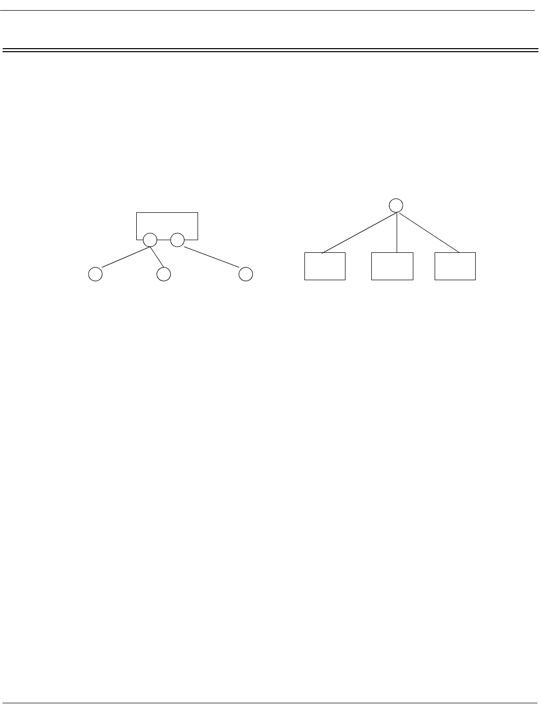
Chapter 11: Documenting Software Interfaces
Copyright 2001 Addison Wesley, all rights reserved 277 Draft for review: Do not circulate without permission
|| END SIDEBAR/CALLOUT ON MULTIPLE INTERFACES
Sometimes interfaces are depicted by themselves, without the element whose interface it is. When actors are
shown interacting through this interface with no associated element, it indicates that any element implementing
the interface can be used. This is a useful means of expressing a particular kind of variability: the ability to sub-
stitute realizing elements. Figure 72(a) illustrates.
We say that an interface is
realized by the element that implements it. Graphically this is usually shown as a
line resembling relationships among elements. Figure 72(b) illustrates.
Primary
Server
Client 1 Client 2
Backup
Server
Figure 72: An interface can be shown separately from any element that realizes it. This emphasiz-
es the interchangeability of element implementations.
(a) Another version of Figure 70(b). This one
shows the primary server interacting with the
interfaces of Client 1, Client 2, and Backup
Server without showing those elements. The
emphasis here is on the interface. Elsewhere
the architect can show (or list) the possible el-
ements that realize each interface.
(b) If an interface is shown by itself, it empha-
sizes that there are many elements that can re-
alize it. If a specific set of possibilities has
been identified, their candidacy can be shown
graphically by using a figure like this.
Product 1
v2.0.5
Product 1
v3.0
Product 2
v1.1
Primary server
realized byrealized by
realized by

Documenting Software Architectures Clements, Bachmann, Bass, Garlan, Ivers, LIttle, Nord, Stafford
Copyright 2001 Addison Wesley, all rights reserved 278 Draft for review: Do not circulate without permission
Figure 73 illustrates how interfaces are shown in UML.
These pictures, while showing the existence of an interface, reveal very little about the definition of an interface:
the resources it provides or requires, or the nature of its interactions. This information must be provided in the
supporting documentation that accompanies the primary presentation.
Notations for conveying syntactic information
The OMG’s Interface Definition Language (IDL) is a language used in the CORBA community to specify inter-
faces’ syntactic information. It provides language constructs to describe data types, operations, attributes, and
exceptions. But the only language support for semantic information is a comment mechanism. An example of
an IDL interface specification begins on page 280.
Most programming languages have built-in ways to specify the signature of an element. C header (.h) files and
Ada package specifications are two examples.
Finally, using the <<interface>> stereotype in UML (as shown in Figure 73) provides the means for conveying
syntactic information about an interface. At a minimum, the interface is named; in addition, the architect can
specify signature information as well.
Notations for conveying semantic information
The most widespread notation for conveying semantic information is natural language. Boolean algebra is often
used to write down preconditions and postconditions, which provide a relatively simple and effective method
for expressing semantics.
<<subsystem>>
C
Figure 73: Showing interfaces in UML. UML uses a “lollipop” to denote an interface, which can be
appended to classes and subsystems, among other things. UML also allows a class symbol (box) to
be stereotyped as an interface; the open-headed dashed arrow shows that an element realizes an in-
terface. The bottom part of the class symbol can be annotated with the interface’s signature informa-
tion: method names, arguments and argument types, etc. The ‘lollipop’ notation is normally used to
show dependencies from elements to the interface, while the box notation allows a more detailed in-
terface description such as the operations provided by the interface.
Class
Interface
Key:
Class
A
<<Interface>>
A
A
realizes

Chapter 11: Documenting Software Interfaces
Copyright 2001 Addison Wesley, all rights reserved 279 Draft for review: Do not circulate without permission
Semantic information often includes the behavior of an element or one or more of its resources. In that case,
any number of notations for behavior come into play.
For more information...
Notations for behavior are detailed in Chapter 8 ("Documenting Behavior").
Summary of notations for interface documentation
Currently there is no single notation that does an adequate job of documenting interfaces; practitioners will have
to employ a combination. Show the existence of interfaces in the views’ primary presentations, using the graph-
ical notation of choice. Use one of the syntactic notations to document the interface’s signature. Semantic in-
formation can be conveyed using natural language, boolean algebra for pre- and post-conditions, or any of the
behavior languages. Patterns of usage, or protocols, can be documented as rich connectors, or by showing
usage scenarios accompanied by examples of how to use the element’s resources to carry out each scenario.
Coming to Terms
“Signature”
“API”
“Interface”
Three terms that people use when discussing the subject of element interactions are “signature,” “API”,
and “interface.” Often they use the terms interchangeably, with unfortunate consequences for their
projects.
We have already defined an interface to be how an element interacts with its environment, and we have
seen that documenting an interface consists of naming and identifying it, documenting syntactic informa-
tion, and documenting semantic information.
A signature deals with the syntactic part of the task. When an interface’s resources are invokable pro-
grams, each comes with a signature that names the program and defines the parameters it takes. Param-
eters are defined by giving their order, data type, and (sometimes) whether or not their value is changed
by the program. A program’s signature is the information that you would find about it, for instance, in the
element’s C or C++ header file.
An API, or “application program interface,” is a vaguely defined term that people use in a variety of ways
to convey interface information about an element. Sometimes people assemble a collection of signatures
and call that an element’s API. Sometimes people add statements about programs’ effects or behavior
and call that an API. An API for an element is usually written to serve developers who are going to use
the element.
Signatures and APIs are useful, but are only part of the story. Signatures can be used, for example, to
enable automatic build checking. This is accomplished by matching the signatures of different elements’
expectations of an interface, often simply by linking different units of code together. Signature matching
will guarantee that a system will compile and/or link successfully. But it guarantees nothing about whether
the system will operate successfully, which is after all the ultimate goal.
For a simple example, consider two elements: One provides a read() method and the other wants to use
a read() method. Let’s assume the signatures match as well. So a simple automated check would deter-

Documenting Software Architectures Clements, Bachmann, Bass, Garlan, Ivers, LIttle, Nord, Stafford
Copyright 2001 Addison Wesley, all rights reserved 280 Draft for review: Do not circulate without permission
mine that the elements are compatible. But, suppose the read() method is implemented such that it re-
moves data from its stream as read() is executed. The user, on the other hand, assumes that read() is
side-effect free and hence can read and re-read the same data. There’s a semantic mismatch here that
will lead to errors, and is why interfaces need to be specified beyond signatures.
As we have seen, a full-fledged interface is written for a variety of stakeholders, includes “requires” as well
as “provides” information, and specifies the full range of effects of each resource, including quality at-
tributes. Signatures and low-end APIs are simply not enough to let an element be put to work with confi-
dence in a system, and a project that adopts them as a short-cut will pay the price when the elements are
integrated (if they’re lucky) but more than likely after the system has been delivered to the customer.
An analogy can be found in aviation. Every year in the United States, the Federal Aviation Administration
and the National Transportation Safety Board spend millions of dollars tracking down counterfeit, low-
quality aircraft parts. Jet engines, for example, are attached to aircraft by very special bolts that have been
engineered to have the right strength, durability, flexibility, and thermal properties. The next time you
board a jet aircraft, imagine that the mechanic who re-attached the jet engines after their last overhaul
used whatever bolts happened to be lying around the parts bin that were long enough and thick enough.
That’s the mechanical engineering version of signature-matching.
|| END SIDEBAR/CALLOUT “Interface” / “Signature” / “API”
11.6 Examples of Documented Interfaces
Following are a few examples of interface documentation taken from actual projects. For each, we will point out
what it shows and does not show.
Interface Example #1: SCR-style Interface
The first example comes from a software engineering demonstration project run by the U. S. Navy, called the
Software Cost Reduction (SCR) project. One of the goals of the project was to demonstrate model documen-
tation of software architecture, including interfaces. The example shown here is for a module generator. The
interface is shown for both the generator and the generated elements. The generated module lets actors create
and manipulate tree data structures with characteristics determined by the generation step.
In the SCR style, each interface document begins with an introduction that identifies the element and provides
a brief account of its function:
Interface Specifications for the Tree Module
TREE.1 Introduction
This module provides facilities for manipulating ordered trees. A complete discussion of ordered trees
(hereafter simply called trees) appears in [KNUTH]; for the purposes of this specification, the following
definitions will suffice:
A tree is a finite non-empty set T of nodes partitioned into disjoint non-empty subsets { {R}, T1, ..., Tn },
n>=0, where R is the root of T and each subset Ti is itself a tree (a subtree of R). The root of each Ti is a
child of R, and R is its parent. The children of R (siblings of one another) are ordered, being numbered
from 1 to n, with child 1 the eldest and child n the youngest. Every node also stores a value.

Chapter 11: Documenting Software Interfaces
Copyright 2001 Addison Wesley, all rights reserved 281 Draft for review: Do not circulate without permission
The size of the tree T is the number of nodes in T. The degree of a node is the number of children it has;
a node of degree 0 is a leaf. The level of a node in a tree is defined with respect to the tree’s root: the root
is at level 1, and the children of a level N node are at level N+1. The height (sometimes also called depth)
of a tree is the maximum level of any node in the tree.
Using the facilities defined in section TREE.2.1, a user provides (1) a name N for a type whose variables
can hold values that denote tree nodes, and (2) the type D of values that a tree node can hold. This gen-
erates a submodule that defines the type N and implements the operations on variables of type N speci-
fied in section TREE.2.2. These operations include creating, deleting, and linking nodes, and fetching
and storing the datum associated with each node.
Some of the generated access programs return a special value to indicate that there exists no node meet-
ing some criterion; except for obtaining this value directly (via +g_null_node+) and performing a few tests
to distinguish it from other values, no operations can be performed on it.
Where x and y are both of type !<N>!, the notation “x = y” simply abbreviates the expression
“+g_are_equal+(x,y)”. Similarly, “x ~= y” abbreviates “~+g_are_equal+(x,y)”.
SCR-style interfaces do not include a usage guide per se, but notice how the introduction explains basic con-
cepts and talks about how the element can be used.
The next part of an SCR interface is a table that specifies the syntax of the resources, and provides a quick-
reference summary of those resources (in this case, method-like routines called
access programs). The pro-
grams are named, their parameters are defined, and the exceptions detected by each are listed. Parameters
are noted as “I” (input), “O” (output), or “O_RET” (returned as function results). This quick-reference summary,
called an Interface Overivew, provides the signature for the resources in a language-independent fashion.
TREE.2 Interface Overview
TREE.2.1 Generator Access Program
Effects
++gen++ If any exception is detected:
The Unix command H TREE_gen ‘U’ ‘E’ is executed, where
H = the command specified in p6, or “echo 1>&2” if p6 is omitted
U = the name of the exception
E = !!extra info!!.
p7 ~= 0.
Otherwise:
C language source code for the module that is specified by section TREE.2.2 with the
Program
Name
Par am ete r typ e Parameter info Exceptions
++gen++ p1: id; I
p2: name; I
p3: typename; I
p4: integer; I
p5: integer; I
p6: string; I-OPT
p7: integer; O-RET
value for !<ID>!
value for !<N>!
value for !<D>!
value for !<capacity>!
value for !<max fanout>!
exception handler command
return code
%%bad capacity%%
%%bad id%%
%%bad max fanout%%
%%bad name%%
%%bad typename%%
%%cannot write%%
%%conflict%%
%%io error%%
%%recursive%%
%%system error%%
%%too long%%

Documenting Software Architectures Clements, Bachmann, Bass, Garlan, Ivers, LIttle, Nord, Stafford
Copyright 2001 Addison Wesley, all rights reserved 282 Draft for review: Do not circulate without permission
textual substitutions
!<ID>! = p1
!<N>! = p2
!<D>! = p3
!<mod>! = the id part of p3, or the empty string if p3 has no id part
!<capacity>! = p4
!<max fanout>! = p5
is written into the !!output files!! in accordance with [CONV].
p7 = 0.
The source code contains #include lines for DATA.h and,
if !<mod>! ~= ““, for !<mod>!_t.h.
(I.e., if p1 = “A” and p3 = “B.typ”, then source code is
written into files A.c, A.h, A_sg.h, and A_t.h, and the lines
#include “DATA.h”
#include “B.h”
are part of this source code.)
TREE.2.2 Access Programs of Generated Module
Program Name Parameter type Parameter info Exceptions
Programs that inquire about the universe of nodes
+g_avail+ p1: integer; O_RET !+avail+! None
Programs that create and destroy nodes
+new+ p1: !<D>!; I
p2: !<N>!; O_RET
initial datum
new node
%too many nodes%
+destroy_tree+ p1: !<N>!; I root of tree %not a node%
Programs that affect the structure of trees
+add_first+
+add_last+
p1: !<N>!; I
p2: !<N>!; I
reference node
node to adopt
%not a node%
%already a child%
%is root of tree%
%too many children%
+ins_next+
+ins_prev+
p1: !<N>!; I
p2: !<N>!; I
reference node
node to insert
%not a node%
%already a child%
%is root of tree%
%not a child%
%too many children%
+disown+ p1: !<N>!; I node %not a node%
Programs for getting information about the structure of trees

Chapter 11: Documenting Software Interfaces
Copyright 2001 Addison Wesley, all rights reserved 283 Draft for review: Do not circulate without permission
At this point, the syntax of the resources has now been specified. Semantics are provided in two ways. For pro-
grams that simply return the result of a query (called “get” programs, and prefixed with “g_”) the returned argu-
ment is given a name and its value is defined in the term dictionary. These programs have no effect on the future
+g_parent+ p1: !<N>!; I
p2: !<N>!; O_RET
node
parent of p1
%not a node%
+g_first+ p1: !<N>!; I
p2: !<N>!; O_RET
node
!+first child+!
+g_last+ p1: !<N>!; I
p2: !<N>!; O_RET
node
!+last child+!
+g_next+ p1: !<N>!; I
p2: !<N>!; O_RET
node
next younger sibling of p1
+g_prev+ p1: !<N>!; I
p2: !<N>!; O_RET
node
next elder sibling of p1
+g_num+ p1: !<N>!; I
p2: integer; O_RET
node
degree of p1
+g_size+ p1: !<N>!; I
p2: integer; O_RET
node
size of tree whose root is p1
+g_nth+ p1: !<N>!; I
p2: integer; I
p3: !<N>!; O_RET
node
p2-th child of p1
+g_is_in_tree+ p1: !<N>!; I
p2: !<N>!; I
p3: boolean; O_RET
node
root of tree
is p1 in tree whose root is p2?
Programs that deal with nodes
+g_null_node+ p1: !<N>!; O_RET !+null node+! None
+g_is_null_node+ p1: !<N>!; I
p2: boolean; O_RET
node
!+is null node+!
+g_is_node+ p1: !<N>!; I
p2: boolean; O_RET
node
!+is node+!
+g_are_equal+ p1: !<N>!; I
p2: !<N>!; I
p3: boolean; O_RET
node
node
!+equal+!
Programs that deal with the data of nodes
+g_datum+ p1: !<N>!; I
p2: !<D>!; O_RET
node
datum of p1
%not a node%
+s_datum+ p1: !<N>!; I
p2: !<D>!; I
node
datum of p1
Program Name Parameter type Parameter info Exceptions

Documenting Software Architectures Clements, Bachmann, Bass, Garlan, Ivers, LIttle, Nord, Stafford
Copyright 2001 Addison Wesley, all rights reserved 284 Draft for review: Do not circulate without permission
behavior of the element. For all other programs, each has an entry in an “Effects” section that explains its re-
sults. You can think of the effects section as a “precondition/postcondition” approach to specifying semantics,
except that the preconditions are implied by the exceptions associated with each resource. That is, the precon-
dition is that the state described by the exception does
not exist. In the following notice how each statement of
effects is observable; that is, you could write a program to test the specification. For example, an effect of calling
+s_datum+(p1,p2) is that an immediately following call to +g_datum+(p1) returns p2.
TREE.2.2.2 Effects
Note: Because +g_first+, +g_last+, and +g_is_null_node+ are defined completely in terms of other pro-
grams, the effects on these three programs are not listed below; they follow directly from the effects given
on the programs in terms of which they are defined.
+add_first+ +g_num+(p1) = 1+'+g_num+'(p1)
+g_nth+(p1,1) = p2
For all i: integer such that (1<i and i<=1+'+g_num+'(p1)),
+g_nth+(p1,i) = '+g_nth+'(p1,i-1)
+g_num+(p1) > 1==>
( +g_next+(p2) = '+g_nth+'(p1,1)
and +g_prev+('+g_nth+'(p1,1)) = p2
)
+g_parent+(p2) = p1
For all n: !<N>!,
'+g_is_in_tree+'(p1,n) ==>
( +g_size+(n) = '+g_size+'(n) + +g_size+(p2)
and For all k: !<N>!,
'+g_is_in_tree+'(k,p2) ==>
+g_is_in_tree+(k,n)
)
+add_last+ +g_num+(p1) = 1+'+g_num+'(p1)
+g_nth+(p1,+g_num+(p1)) = p2
+g_num+(p1) > 1 ==>
( +g_prev+(p2) = '+g_nth+'(p1,'+g_num+'(p1))
and +g_next+('+g_nth+'(p1,'+g_num+'(p1))) = p2
)
+g_parent+(p2) = p1
For all n: !<N>!,
'+g_is_in_tree+'(p1,n) ==>
( +g_size+(n) = '+g_size+'(n) + +g_size+(p2)
and For all k: !<N>!,
'+g_is_in_tree+'(k,p2) ==>
+g_is_in_tree+(k,n)
)
+destroy_tree+ Let P = '+g_parent+'(p1).
For all c: !<N>!,
'+g_is_in_tree+'(c,p1) ==> ~+g_is_node+(c)
P ~= +g_null_node+() ==>
For some i: integer,
( p1 = '+g_nth+'(P,i)
and For all j: integer > i,
+g_nth+(P,j-1) = '+g_nth+'(P,j)
and +g_num+(P) = '+g_num+'(P) - 1
)

Chapter 11: Documenting Software Interfaces
Copyright 2001 Addison Wesley, all rights reserved 285 Draft for review: Do not circulate without permission
For all n: !<N>! such that '+g_is_node+'(n),
'+g_is_in_tree+'(p1,n) ==>
+g_size+(n) = '+g_size+'(n) - '+g_size+'(p1)
+g_avail+ = '+g_avail+' + '+g_size+'(p1)
+disown+ Let P = '+g_parent+'(p1).
P ~= +g_null_node+() ==>
For some i: integer,
( p1 = '+g_nth+'(P,i)
and For all j: integer > i,
+g_nth+(P,j-1) = '+g_nth+'(P,j)
and +g_num+(P) = '+g_num+'(P) - 1
and For all n: !<N>! such that '+g_is_node+'(n),
'+g_is_in_tree+'(p1,n) ==>
( ~+g_is_in_tree+(p1,n)
and +g_size+(n) = '+g_size+'(n)-'+g_size+'(p1)
and For all c: !<N>!
such that '+g_is_in_tree+'(c,p1),
~+g_is_in_tree+(c,n)
)
)
+g_parent+(p1) = +g_null_node+()
+ins_next+ Let P = '+g_parent+'(p1).
For some i: integer,
( p1 = '+g_nth+'(P,i)
and +g_nth+(P,i+1) = p2
and For all j: integer > i,
+g_nth+(P,j+1) = '+g_nth+'(P,j)
)
+g_num+(P) = 1+'+g_num+'(P)
+g_parent+(p2) = P
+g_next+(p1) = p2
+g_next+(p2) = '+g_next+'(p1)
+g_prev+(p2) = p1
'+g_last+'(P) ~= p1 ==> +g_prev+('+g_next+'(p1)) = p2
For all n: !<N>!,
'+g_is_in_tree+'(P,n) ==>
( +g_size+(n) = '+g_size+'(n) + +g_size+(p2)
and For all k: !<N>!,
'+g_is_in_tree+'(k,p2) ==>
+g_is_in_tree+(k,n)
)
+ins_prev+ Let P = '+g_parent+'(p1).
For some i: integer,
( p1 = '+g_nth+'(P,i)
and +g_nth+(P,i-1) = p2
and For all j: integer >= i,
+g_nth+(P,j+1) = '+g_nth+'(P,j)
)
+g_num+(P) = 1+'+g_num+'(P)
+g_parent+(p2) = P

Documenting Software Architectures Clements, Bachmann, Bass, Garlan, Ivers, LIttle, Nord, Stafford
Copyright 2001 Addison Wesley, all rights reserved 286 Draft for review: Do not circulate without permission
+g_prev+(p1) = p2
+g_prev+(p2) = '+g_prev+'(p1)
+g_next+(p2) = p1
'+g_first+'(P) ~= p1 ==> +g_next+('+g_prev+'(p1)) = p2
For all n: !<N>!,
'+g_is_in_tree+'(P,n) ==>
( +g_size+(n) = '+g_size+'(n) + +g_size+(p2)
and For all k: !<N>!,
'+g_is_in_tree+'(k,p2) ==>
+g_is_in_tree+(k,n)
)
+new+ p2 is assigned a value X such that ~'+g_is_node+'(X).
p2 ~= +g_null_node+()
+g_is_node+(p2)
+g_avail+() = '+g_avail+()' - 1
+g_parent+(p2) = +g_null_node+()
+g_next+(p2) = +g_null_node+()
+g_prev+(p2) = +g_null_node+()
+g_num+(p2) = 0
+g_size+(p2) = 1
For all i: integer, +g_nth+(p2,i) = +g_null_node+()
For all n: !<N>!, +g_is_in_tree+(p2,n) <==> p2 = n
+g_datum+(p2) = p1
+s_datum+ +g_datum+(p1) = p2.
An SCR-style interface continues with a set of dictionaries that explain, respectively, the data types used, se-
mantic terms introduced, exceptions detected, and configuration parameters provided. Configuration parame-
ters represent the element’s variability. Bracket notation lets a reader quickly identify which dictionary contains
a term’s definition: $data type literal$, !+semantic term+!, %exception%, and #configuration parameter#.

Chapter 11: Documenting Software Interfaces
Copyright 2001 Addison Wesley, all rights reserved 287 Draft for review: Do not circulate without permission
TREE.3 Locally Defined Data Types
TREE.4 Dictionary
Type Definition
boolean common type as defined in [CONV]
!<D> ! If !<mod>! = ““, a common type (other than string), as defined in [CONV]. Oth-
erwise, assumed to be defined in the module whose abbreviated module ID is
!<mod>!. In either case, assignment must be possible for this type.
id a string matching the egrep-style regular expression [A-Z]([A-Z_0-9])* (see
[GREP] for how to interpret this)
integer common type as defined in [CONV]
!<N>! The set of values of this type is a secret of this module.
name a string matching the egrep-style regular expression [a-zA-Z]([a-zA-Z_0-9])*
(see [GREP] for how to interpret this).
string common type as defined in [CONV]
typename either a string of the form id.name, or one of “boolean”, “character”, “integer”,
“real”, “string_ptr”.
Term Definition
!+avail+! The number of new nodes that can be created without an intervening call to
+destroy_tree+. Initially = #max_num_nodes#.
!+equal+! p1 and p2 denote the same node (i.e., p1 and p2 contain the same value).
Assignment of a to b makes a and b denote the same node.
!!extra info!! A string containing extra information associated with an exception of ++gen++
and passed to the handler along with the exception name. Defined in the dic-
tionary entry for each exception; if defined as a number, then the string is a
decimal representation of the number.
!+first child+! +g_nth+(p1,1).
!+is node+! Initially = FALSE for all values of p1.
!+is null node+! p1 = +g_null_node+().
!+last child+! +g_nth+(p1,+g_num+(p1)).
!!output files!! The files !<ID>!.c, !<ID>!.h, !<ID>!_t.h, !<ID>!_sg.h.
!+null node+! The unique value x such that +g_is_null_node+(x) and ~+g_is_node(x).

Documenting Software Architectures Clements, Bachmann, Bass, Garlan, Ivers, LIttle, Nord, Stafford
Copyright 2001 Addison Wesley, all rights reserved 288 Draft for review: Do not circulate without permission
TREE.5 Exceptions Dictionary
Exception Definition
%already a child% +g_is_node+(+g_parent+(p2)).
%bad capacity% p4 < 1 or p4 > ##max_capacity##.
!!extra info!! = p4.
%%bad id%% p1 is not of the form specified in the definition of the type “id”.
!!extra info!! = p1.
%%bad max fanout%% p5 < 1 or p5 > (p4 - 1) or p5 > ##max_max_fanout##.
!!extra info!! = p5.
%%bad name%% p2 is not of the form specified in the definition of the type “name”.
!!extra info!! = p2.
%%bad typename%% p3 is not of the form specified in the definition of the type “type-
name”. !!extra info!! = p3.
%%cannot write%% One of the !!output files!! cannot be opened for writing.
!!extra info!! = the name of the file.
%%conflict%% The values of p1-p3 are such that some name in the generated
submodule would have two definitions.
!!extra info!! = the name that would be doubly defined.
%%io error%% The operating system has reported an error when trying to open or
write one of the !!output files!!. !!extra info!! = the name of the file.
%is root of tree% +g_is_in_tree+(p1,p2).
%not a child% ~+g_is_node+(+g_parent+(p1)).
%not a node% For some input parameter pj of type !<N>!, ~+g_is_node+(pj).
%%recursive%% p1 = “DATA” or p1 = “UE” or p3 is of the form id.name where the id
= p1. !!extra info!! = p1 in the first two cases, p3 in the last.
%%system error%% The operating system has reported an error other than %cannot
write% and %io error%. !!extra info!! = the integer code returned
by the operating system to describe the error.
%%too long%% The values of p1-p3 are such that some name in the generated
submodule would be too long for the implementation environment.
In the 4.2bsd environment, file names and C identifiers can have
no more than 255 characters. !!extra info!! = the name that would
be too long.
%too many children% For +add_first/last+: +g_num+(p1) = #max_num_children#.
For +ins_next/prev+: +g_num+(+g_parent+(p1)) =
#max_num_children#.
%too many nodes% For +new+: +g_avail+ = 0.
For +copy_tree+: +g_avail+ < +g_size+(p1).

Chapter 11: Documenting Software Interfaces
Copyright 2001 Addison Wesley, all rights reserved 289 Draft for review: Do not circulate without permission
TREE.6 System Configuration Parameters
Following the dictionaries, an SCR-style interface includes background information: Design issues and ratio-
nale, implementation notes, and a set of so-called
basic assumptions that summarized what the designer as-
sumed would be true about all elements realizing this interface. Those assumptions form the basis of a design
review for the interface.
TREE.7 Design issues
1. How much terminology to define in the introduction.
Several terms (leaf, level, depth) are defined in the introduction but not used anywhere else in this spec-
ification. These terms have been defined here only because they are expected to prove useful in the
specifications of modules that use trees.
2. How to indicate a nonexistent node.
How is the fact that a node has no parent, nth child, or older or younger sibling to be communicated to
users of the module? Two alternatives were considered: (a) Have the access programs that give the par-
ent, etc., of a node return a special value analogous to a null pointer; (b) Have additional access programs
for determining these facts.
Option (a) allows a more compact interface with no less capability, so it was chosen. In addition, option
(a) allows a user to make a table of nodes, some entries of which are empty, much more conveniently.
Thirdly, it has the minor advantage of resembling the common linked implementation of trees, and thus
may be viewed as more natural.
Note that (a) may mimic (b) quite simply; comparing the result of the returned value with the special null
value is equivalent to node has a parent, eldest child, or whatever. If the set of values of type !<N>! is
defined to include a null value, then (b) may also mimic (a), since (b) is then a superset of (a).
3. How to move from node to node.
“Moving from node to node” in fact consists of getting the node that bears the desired relation to the first
node. Several ways of accessing siblings were considered:
(a) Sequentially, allowing moves to the next or previous sibling in the sequence.
(b) By an index, allowing moves to the nth of the sequence of siblings.
(c) Sequentially, but allowing moves of more than one sibling at a time.
Parameter Definition
##max_capacity## The maximum value of #max_num_nodes# for any generated sub-
module.
##max_max_fanout## The maximum value of #max_num_children# for any generated sub-
module.
#max_num_children# The maximum number of children that any node can have ( = !<max
fanout>!).
#max_num_nodes# The maximum number of nodes that can exist at a time ( = !<capac-
ity>!).

Documenting Software Architectures Clements, Bachmann, Bass, Garlan, Ivers, LIttle, Nord, Stafford
Copyright 2001 Addison Wesley, all rights reserved 290 Draft for review: Do not circulate without permission
Option (c) seemed of marginal utility and was thus not included. Option (b) was included for generality.
Although (a) is not strictly necessary if (b) is available, (a) was nevertheless also included because (a)
can usually be implemented in a considerably more efficient manner.
4. Whether to allow a node with no datum.
Should a node be allowed to have no datum? In an earlier version, this was allowed. The question then
was whether “no datum” should be represented by a special null data value or by an access program that
checks and returns a boolean. Since no null data value could be guaranteed for an arbitrary data type,
and since the module accomodated arbitrary types, the second alternative was initially chosen. There
was a program +g_has_datum+(p1), which returned FALSE immediately after +new+ returned p1 or
+clear+(p1) was called. There was also an exception %has no datum% applicable to +g_datum+.
Upon reflection, it seemed better to require that an initial datum be given as a second argument to +new+
and to eliminate +clear+, so that a node must always have a datum. This meant that +g_has_datum+ and
%has no datum% were no longer needed. Requiring that a node always have a datum is analogous to
forbidding uninitialized variables in programs, and results in a considerable simplification of this module.
In cases where users need to have nodes that sometimes contain no valid data, this can easily be ar-
ranged using the DU module, by reserving one of the types represented by a discriminated union to mean
“no valid datum” and initializing the datum of each new node to a value of that type.
5. Type of a node.
The type of data that can be associated with a node could either be bound permanently when the node is
created or be varied dynamically. Dynamic binding was initially chosen because it offers more flexibility
for small cost. However, it was later recognized that dynamic typing really does not belong in this module.
This function has been moved to the discriminated union module (DU). This has considerably simplified
the interface of this module.
6. Determining whether a given tree contains a given node.
Although this can be determined by using other access programs, putting it on the interface costs little
because detection of %is root of tree% already requires that this function be implemented inside the mod-
ule. Therefore, +g_is_in_tree+ was added.
7. How should the actual value of the null node be made available?
A user who made a table of nodes would find it convenient to use the null node to denote empty entries.
This value can be obtained by various sequences of operations in any case; +g_null_node+ was provided
to make it convenient and straightforward.
8. Should there be a sysgen parameter that limits the number of nodes?
Although dynamic storage allocation would make such a limit unnecessary, this is not available in all lan-
guages. Furthermore, such a limit may be useful in detecting errors (for example, nonterminating loops)
in programs that use this module. Therefore, #max_num_nodes# has been provided.
9. Should there be a sysgen parameter that limits the number of children any one node may have?
Such a limit would be useful for an implementation that favored nodes with some given number of chil-
dren. This limit might also be useful in detecting errors in programs that use this module. Therefore,
#max_num_children# has been provided. Where not required by an implementation, the limit may be ef-
fectively disabled by having #max_num_children# >= (#max_num_nodes#-1).
10. Is a comparison operation for nodes needed?
Such an operation is unnecessary for some implementations of the data type !<N>!. For those implemen-
tations, the equality operation of the language of implementation suffices.
However, this would not work for some combinations of implementations and programming languages.
An example would be the implementation of nodes as structures containing validity information in a lan-
guage (e.g., C) that does not allow comparison of structures. Therefore, +g_are_equal+ is provided.
TREE.8 Implementation Notes: none
TREE.9 Assumptions
1. The children of a node must be ordered.

Chapter 11: Documenting Software Interfaces
Copyright 2001 Addison Wesley, all rights reserved 291 Draft for review: Do not circulate without permission
2. It suffices that construction of trees be possible by a combination of creation of trees consisting of sin-
gle nodes and attachment of trees as subtrees of nodes.
3. For our purposes, the following manipulations of trees are sufficient: (1) Replication of a tree (2) Addi-
tion of a subtree at either end of the list of subtrees of a node (3) Insertion of a subtree before or after a
subtree in the list of subtrees of a node (4) Disassociation of a subtree from the tree that contains it
4. For our purposes, the following means of traversing a tree are sufficient: (1) Get the parent of a node
(2) Get the eldest child of a node (3) Get the next or previous sibling of a node
5. The resources devoted to a tree may be freed.
6. Each node must have a datum associated with it; the type of this datum can be the same for every
node and can be fixed at sysgen time.
7. Only values of type !<N>! representing existing nodes will be passed as input parameters to access
programs that operate on nodes.
8. No node may be a child of more than one parent.
9. No node may be an ancestor of itself.
10. No attempt will be made to cause more than some fixed number of nodes to exist simultaneously.
11. No attempt will be made to give a node more than some fixed number of children.
Not shown in this example is an efficiency guide that lists the time requirements of each resource, the SCR
analog to the quality attribute characteristics that we prescribe in our outline for an interface.
Table 24 shows how SCR-style interface specifications stack up against the template of Figure 68.
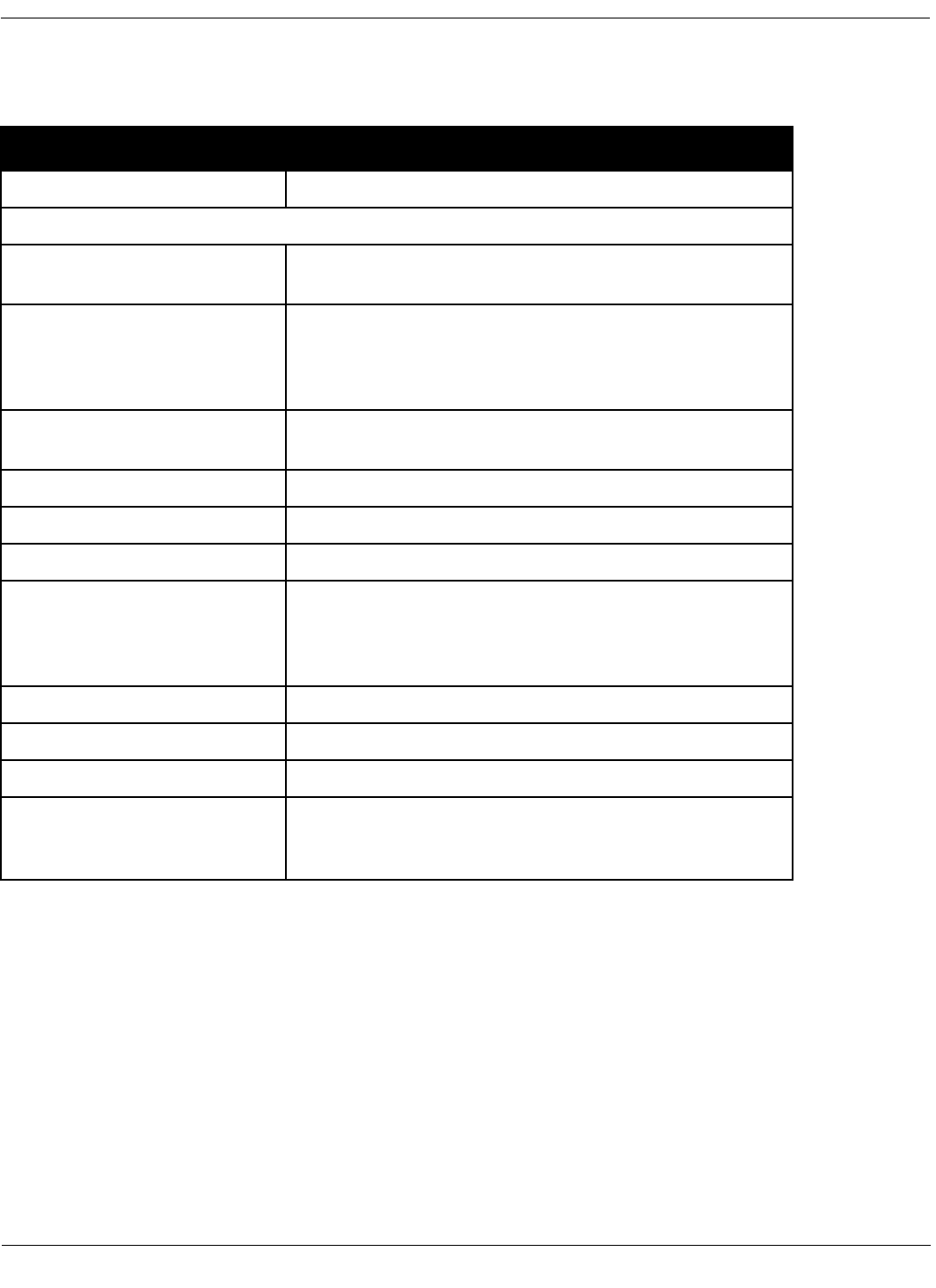
Documenting Software Architectures Clements, Bachmann, Bass, Garlan, Ivers, LIttle, Nord, Stafford
Copyright 2001 Addison Wesley, all rights reserved 292 Draft for review: Do not circulate without permission
Table 24: Checklist for SCR-style interface specifications
Interface information SCR-style interface
1. Interface identity Yes.
2. Resources provided
a. Resource syntax Yes, in interface overview. Syntax is given in quick-refer-
ence tabular form, independent of language.
b. Resource semantics Yes. Programs that return values have those values
defined in a dictionary. Other programs have effects
specified in terms of future observable behavior of ele-
ment’s resources.
c. Resource usage restric-
tions
Yes. Exceptions associated with each resource imply
usage restrictions.
3. Locally defined data types Yes.
4. Exceptions Yes.
5. Variability provided Yes, in the form of system configuration parameters.
6. Quality attribute characteris-
tics
SCR-style interfaces come with an effiiciency guide (not
shown) that provides information about the real-time per-
formance of its elements’ resources. Other quality
attributes could be described here as well.
7. What the element requires No
8. Rationale and design issues Yes, captured explicitly.
9. Implementation notes Yes, captured explicitly.
10. Usage guide Not explicitly, but the introductory section of the spec
usually contains basic concepts and broad hints about
how to the resources in concert with each other.

Chapter 11: Documenting Software Interfaces
Copyright 2001 Addison Wesley, all rights reserved 293 Draft for review: Do not circulate without permission
Interface Example #2: An Interface Documented Using IDL
A small, sample interface specified in OMG IDL is shown in Figure 74. The interface is for an element that man-
ages a bank account.
While syntax is specified unambiguously in this type of documentation, semantic information is largely missing.
For example, can a user make arbitrary withdrawals? Withdrawals only up to the current account balance? Up
to some daily limit? Up to some minimum balance? If any of these restrictions are true, what happens if they’re
violated? Is the maximum permissible amount withdrawn, or is the transaction as a whole cancelled?
IDL
by itself is inadequate when it comes to fully documenting an interface. This is primarily because IDL offers
no language constructs for discussing the semantics of an interface, and without expression of the semantics,
ambiguities and misunderstandings will abound.
interface Account {
readonly attribute string name;
readonly attribute float balance;
void deposit (in float amount);
void withdraw (in float amount);
};
interface CheckingAccount: Account {
readonly attribute float overdraft_limit;
void order_new_checks ();
};
interface SavingsAccount: Account {
float annual_interest ();
};
interface Bank {
CheckingAccount open_checking (
in string name, in float starting_balance);
SavingsAccount open_savings (
in string name, in float starting_balance);
};
Figure 74: An example of IDL for an element in a banking application, from [Bass 98]. The element
provides resources to manage a financial account. An account has attributes of “balance” and “own-
er”. Operations provided are deposit and withdraw programs.

Documenting Software Architectures Clements, Bachmann, Bass, Garlan, Ivers, LIttle, Nord, Stafford
Copyright 2001 Addison Wesley, all rights reserved 294 Draft for review: Do not circulate without permission
“”
“An interface definition written in OMG IDL completely defines the interface and
fully specifies each operation’s parameters. An OMG IDL interface provides the
information needed to develop clients that use the interface’s operations.”
-- CORBA 2.3 specification, IDL Syntax and Semantics description Chapter 3
Table 25 shows how an interface documented in IDL compares to the template of Figure 68.
Interface Example #3: An Interface in the HLA Style
The High Level Architecture (HLA) was initially developed by the United States Department of Defense (DoD)
to provide a common architecture for distributed modeling and simulation. To facilitate intercommunication, HLA
allows simulations and simulators (called federates) to interact with an underlying software infrastructure known
as the Runtime Infrastructure (RTI). The HLA requires that communications with the RTI use a standard appli-
cation programmer’s interface (API) that is defined in an IEEE standard [IEEE P1516.1-2000, IEEE Standard
for Modeling and Simulation (M&S) High Level Architecture (HLA) - Federate Interface Specification].
Table 25: Checklist for IDL interface specifications
Interface information IDL interface
1. Interface identity Yes.
2. Resources provided
a. Resource syntax Yes.
b. Resource semantics No
c. Resource usage restric-
tions
No
3. Locally defined data types No
4. Exceptions No
5. Variability provided No
6. Quality attribute characteris-
tics
No
7. What the element requires No
8. Rationale and design issues No
9. Implementation notes No
10. Usage guide No

Chapter 11: Documenting Software Interfaces
Copyright 2001 Addison Wesley, all rights reserved 295 Draft for review: Do not circulate without permission
The RTI provides services to federates in a way that is analogous to how a distributed operating system pro-
vides services to applications. The interface document defines the standard services and interfaces to be used
by the federates in order to support efficient information exchange when participating in a distributed federation
execution.
This is an example in which the focus is on defining an interface that will be realized by a number of different
elements. HLA was built to facilitate interoperability among simulations built by different parties. Hence, simu-
lations can be built by combining elements the represent different players into what is called a federation. Any
element that realizes the HLA interface is a viable member of the simulation, and will be able to interact mean-
ingfully with other elements in the simulation that are representing other active parties.
Because of the need to assure meaningful cooperation among elements that were built with very little knowl-
edge of each other, a great deal of effort went into specifying not just the syntax of the interface, but also the
semantics. The extract from the HLA Interface Specification presented in Figure 75 describes a single resource
(a method) of the interface. Lists of preconditions and postconditions are associated with the resource, and the
introduction provides a context for the resource and explains its use within the context of the full HLA interface.
The resource (method) is called “Negotiated Attributed Ownership Divestiture.”
The full HLA interface document contains over 140 resources like the one in Figure 75, and the majority have
some interaction with other resources. For example, using some resources will cause the preconditions of the
presented resource to no longer be true (with respect to specific arguments). There are a number of such re-
strictions on the order in which the resources can be used.
A careful reading of all the preconditions and postconditions of the 140 resources will reveal these restrictions,
but it is not a trivial exercise. It’s unrealistic to expect every user of the interface document to go through this
kind of exercise. To facilitate an understanding of the implicit protocol of usage among the resources, the HLA
interface document also presents a summary view of this information. The statechart in Figure 76 depicts the
constraints on the order of use of a specific set of the resources. This type of summary information is valuable
both in providing an introduction to the complexities of an interface and in providing a concise reminder to those
already familiar with the interface.

Documenting Software Architectures Clements, Bachmann, Bass, Garlan, Ivers, LIttle, Nord, Stafford
Copyright 2001 Addison Wesley, all rights reserved 296 Draft for review: Do not circulate without permission
Negotiated Attribute Ownership Divestiture
Overview
The Negotiated Attribute Ownership Divestiture service shall notify the RTI that the joined federate
no longer wants to own the specified instance attributes of the specified object instance. Ownership
shall be transferred only if some joined federate(s) accepts. When the RTI finds federates willing to
accept ownership of any or all of the instance attributes, it will inform the divesting federate using the
Request Divestiture Confirmation † service (supplying the appropriate instance attributes as argu-
ments). The divesting federate may then complete the negotiated divestiture by invoking the
Confirm
Divestiture
service to inform the RTI of which instance attributes it is divesting ownership. The
invoking joined federate shall continue its update responsibility for the specified instance attributes
until it divests ownership via the
Confirm Divestiture service. The joined federate may receive one or
more
Request Divestiture Confirmation † invocations for each invocation of this service since differ-
ent joined federates may wish to become the owner of different instance attributes.
A request to divest ownership shall remain pending until either the request is completed (via the
Request Divestiture Confirmation † and Confirm Divestiture services), the requesting joined federate
successfully cancels the request (via the
Cancel Negotiated Attribute Ownership Divestiture service),
or the joined federate divests itself of ownership by other means (e.g., the
Attribute Ownership Dives-
titure If Wanted
or Unpublish Object Class Attributes service). A second negotiated divestiture for an
instance attribute already in the process of a negotiated divestiture shall not be legal.
Supplied Arguments
Object instance designator
Set of attribute designators
User-supplied tag
Returned Arguments
None
Pre-conditions
The federation execution exists.
The federate is joined to that federation execution.
An object instance with the specified designator exists.
The joined federate knows about the object instance with the specified designator.
The joined federate owns the specified instance attributes.
The specified instance attributes are not in the negotiated divestiture process.
Save not in progress.
Restore not in progress.
Post-conditions
No change has occurred in instance attribute ownership.
The RTI has been notified of the joined federate's request to divest ownership of the specified
instance attributes.
Exceptions
The object instance is not known
The class attribute is not available at the known class of the object instance
The joined federate does not own the instance attribute
The instance attribute is already in the negotiated divestiture process
The federate is not a federation execution member
Save in progress
Restore in progress
RTI internal error
Figure 75: Example of documentation for an interface resource, taken from the HLA.

Chapter 11: Documenting Software Interfaces
Copyright 2001 Addison Wesley, all rights reserved 297 Draft for review: Do not circulate without permission
Notice that the one thing that the IDL example presented very clearly (the syntax of the resources) is lacking in
what has been shown so far in the HLA example. In fact, the HLA interface documentation distinguishes be-
tween what it calls an “abstract interface document” (as shown above) and a number of different programming
language representations of the interface (each of which is specified in a manner similar to the IDL example).
This separation is an example of how an interface document can be packaged into units that are appropriate
for different stakeholders. The semantic specification is sufficient for architects examining the HLA for potential
use. Developers of elements implementing the interface, on the other hand, will need both the semantic spec-
ification and one or more of the programming language representations (for syntactic information).
Table 26 shows how an HLA interface compares to the template of Figure 68.
Establishing Ownership of Instance Attribute (i, k, j)
Owned (i, k, j)
Negotiated
Attribute
Ownership
Divestiture
Cancel
Negotiated
Attribute
Ownership
Divestiture
Not Divesting
Waiting for a New
Owner to be Found
Willing to
Acquire (i, k, j)
Not Trying
to Acquire
Attribute
Ownership
Acquisition
If Available
[not in
“Acquisition
Pending”]
Request Attribute Ownership
Assumption
† [not in “Acquiring (i,k,j)”
^ not in “Willing to Acquire (i,k,j)”]
Non-intrusive Acq
Trying to
Cancel Acq
(i, k, j)
Acquiring
(i, k, j)
Acquisition Pending
Cancel Attribute
Ownership
Acquisition
Confirm
Attribute
Ownership
Acquisition
Cancellation†
Not
Acquiring
Intrusive Acq
Attribute
Ownership
Acquisition
[ in “Unpublished (i, j)” ]
[ in “Published (i, j)” ]
Not Able
to Acquire
Unowned
(i, k, j)
[ in “Unpublished (i, j)” ]
[ Discover
† v
in “Unpublished (i, j)” ]
[ Register
^
in “Published (i, j)” ]
C
C
Able to Acquire
Attribute
Ownership
Unavailable
†
or
[ in “
Acquisition
Pending” ]
H
[ in “Unpublished (i, j)” ]
Confirm
Divestiture
Attribute
Ownership
Acquisition
Notification
†
Unconditional
Attribute
Ownership
Divestiture
Attribute
Ownership
Acquisition
Notification†
[ in “Published (i, j)” ]
Request
Attribute
Ownership
Release †
H
Attribute Ownership
Divestiture If Wanted
(ret: kept)
Attribute
Ownership
Divestiture
If Wanted
(ret: divested)
Completing Divestiture
Request
Divestiture
Confirmation
†
Cancel Negotiated
Attribute Ownership
Divestiture
Figure 76: This Statechart shows the constraints on the order of use of a specific set of
the resources. Statecharts like this show an entire protocol in which the resource is used.
The method described earlier is in the top center, highlighted in red. This shows the states
during in which the method can be invoked, and the state that is entered when it is in-
voked.

Documenting Software Architectures Clements, Bachmann, Bass, Garlan, Ivers, LIttle, Nord, Stafford
Copyright 2001 Addison Wesley, all rights reserved 298 Draft for review: Do not circulate without permission
A Microsoft API
tbd
Table 27 shows how the Microsoft API fares against the interface document template of Figure 68.
Table 26: Checklist for HLA interface specifications
Interface information HLA interface
1. Interface identity Yes.
2. Resources provided
a. Resource syntax Represented separately, in a programming-language-
specific rendition of the interface.
b. Resource semantics Yes, via preconditions and postconditions.
c. Resource usage restric-
tions
Yes, via exceptions.
3. Locally defined data types No
4. Exceptions Yes
5. Variability provided No
6. Quality attribute characteris-
tics
No
7. What the element requires No
8. Rationale and design issues No
9. Implementation notes No
10. Usage guide Not explicit, but the introduction can hold helpful informa-
tion about suggested usage. The intertwined usage of
large numbers of elements can also be documented sep-
arately, such as in the Statechart of Figure 76.

Chapter 11: Documenting Software Interfaces
Copyright 2001 Addison Wesley, all rights reserved 299 Draft for review: Do not circulate without permission
11.7 Glossary
• interface
• resource
• exception
• ...
Table 27: Checklist for Microsoft-style API
Interface information Microsoft-style API
1. Interface identity
2. Resources provided
a. Resource syntax
b. Resource semantics
c. Resource usage restric-
tions
3. Locally defined data types
4. Exceptions
5. Variability provided
6. Quality attribute characteris-
tics
7. What the element requires
8. Rationale and design issues
9. Implementation notes
10. Usage guide

Documenting Software Architectures Clements, Bachmann, Bass, Garlan, Ivers, LIttle, Nord, Stafford
Copyright 2001 Addison Wesley, all rights reserved 300 Draft for review: Do not circulate without permission
11.8 Summary checklist
tbd
Advice
11.9 For Further Reading
Interfaces:
• Refer to DIM paper in Parnas Papers as source for A-7E interface information.
• Refer to Parnas and Wuerges as a good background paper on exceptions (also in Parnas Papers).
• Mary Shaw has taken the observation that we can’t ever have complete interfaces and made useful
work out of writing down information we have about the information we have. She calls a partial
interface a credential, and assigns it properties such as how we know it and what confidence we have
in it. This is a treatment of interfaces for the world in which we get our components from unknown
sources and know precious little about them.
11.10Discussion Questions
TBD
1. For an interface specification that you’re familiar with, fill out a table for it as in Table 24 on page 292 and
see how it stacks up.
2. What’s the difference between an interface and a connector? Discuss.
?

Chapter 12: Reviewing Software Architecture Documentation
Copyright 2001 Addison Wesley, all rights reserved 301 Draft for review: Do not circulate without permission
Chapter 12: Reviewing Software Architecture
Documentation
This chapter is still very much under construction.
have stakeholder groups write validation questions -- this is kb’s idea to extend ADRs.
add to acks: the ideas in this chapter came from workshop.
12.1 Introduction
Recall the seventh rule of sound documentation:
Advice
7. Review documentation for fitness of purpose.
“Only the intended users of a document will be able to tell you if it contains the right information presented in
the right way,” we said back then. “Enlist their aid. Before a document is released, have it reviewed by repre-
sentatives of the community or communities for whom it was written.”
This chapter will outline an approach for reviewing architectural documentation to help you make certain that
the documentation you have put forth considerable effort to produce will in fact be useful to the communities
you’ve aimed to serve.
This chapter is not about making sure you have designed the right architecture; there are other published re-
sources to help with that task. This is about making sure that the architecture you have is well enough described
so that people can understand and use it.
A review of architecture documentation has these three objectives:
1. Were the right views chosen?
2. Is the documentation useful to the right stakeholders?
3. Is the documentation consistent with the templates and standard organizations you selected for it?

Documenting Software Architectures Clements, Bachmann, Bass, Garlan, Ivers, LIttle, Nord, Stafford
Copyright 2001 Addison Wesley, all rights reserved 302 Draft for review: Do not circulate without permission
The reviews prescribed in this chapter are based on a technique called active design reviews.
“”
Active Reviews
David M. Weiss, Director of Software Technology Research, Avaya Labs
Starting in the early 1970s I have had occasion to sit in on a number of design reviews, in disparate places
in industry and government. I had a chance to see a wide variety of software developers conduct reviews,
including professional software developers, engineers, and scientists. All had one thing in common: the
review was conducted as a (usually large) meeting or series of meetings at which designer(s) made pre-
sentations to the reviewers, and the reviewers could be passive and silent or could be active and ask
questions. The amount, quality, and time of delivery of the design documentation varied widely. The time
that the reviewers put in preparation varied widely. The participation by the reviewers varied widely. (I
have even been to so-called reviews where the reviewers are cautioned not to ask embarrassing ques-
tions, and have seen reviewers silenced by senior managers for doing so. I was once hustled out of a
design review because I was asking too many sharp questions.) The expertise and roles of the reviewers
varied widely. As a result, the quality of the reviews varied widely. In the early 1980s Fagin-style code in-
spections were introduced to try to ameliorate many of these problems for code reviews. Independently
of Fagin, we developed active design reviews at about the same time to ameliorate the same problems
for design reviews.
Active design reviews are designed to make reviews useful to the designers. They are driven by ques-
tions that the designers ask the reviewers, reversing the usual review process. The result is that the de-
signers have a way to test whether or not their design meets the goals they have set for it. To get the
reviewers to think hard about the design, active reviews try to get them to take an active role by requiring
them to answer questions rather than to ask questions. Many of the questions force them to take the role
of users of the design, sometimes making them think about how they would write a program to implement
(parts of) the design. In an active review, no reviewer can be passive and silent.
We focus reviewers with different expertise on different sets of questions so as to use their time and knowl-
edge most effectively. There is no large meeting at which designers make presentations. We conduct an
initial meeting where we explain the process and then give reviewers their assignments, along with the
design documentation that they need to complete their assignments.
Design reviews cannot succeed without proper design documentation. Information theory tells us that er-
ror correction requires redundancy. Active reviews use redundancy in two ways. First, we suggest that
designers structure their design documentation so that it incorporates redundancy for the purpose of con-
sistency checking. For example, module interface specifications may include assumptions about what
functionality the users of a module require. The functions offered by the module’s interface can then be
checked against those assumptions. Incorporating such redundancy is not required for active design re-
views but certainly makes it easier to construct the review questions.
Second, we select reviewers for their expertise in certain areas and include questions that take advantage
of their knowledge in those areas. For example, the design of avionics software would include questions
about devices controlled or monitored by the software, to be answered by experts in avionics device tech-
nology, and intended to insure that the designers have made correct assumptions about the characteris-
tics, both present and future, of such devices. In so doing, we compare the knowledge in the reviewers’
heads with the knowledge used to create the design.
I have used active design reviews in a variety of environments. With the proper set of questions, appro-
priate documentation, and appropriate reviewers, they never fail to uncover many false assumptions, in-
consistencies, omissions, and other weaknesses in the design. The designers are almost always pleased
with the results. The reviewers, who do not have to attend a long, often boring, meeting, like being able
to go off to their desks and focus on their own areas of expertise, with no distractions, on their own sched-
ule. One developer who conducted an active review under my guidance was ecstatic with the results. In
response to the questions she used she had gotten more than 300 answers that pointed out potential
problems with the design. She told me that she had never before been able to get anyone to review her
designs so carefully.

Chapter 12: Reviewing Software Architecture Documentation
Copyright 2001 Addison Wesley, all rights reserved 303 Draft for review: Do not circulate without permission
Of course, active reviews have some difficulties as well. As with other review approaches, it is often diffi-
cult to find reviewers who have the expertise that you need and who will commit to the time that is re-
quired. Since the reviewers operate independently and on their own schedule, you must sometimes
harass them to get them to complete their reviews on time. Some reviewers feel that there is a synergy
that occurs in large review meetings that ferrets out problems that may be missed by individual reviewers
carrying out individual assignments. Perhaps the most difficult aspect is creating design documentation
that contains the redundancy that makes for the most effective reviews. Probably the second most difficult
aspect is devising a set of questions that force the reviewer to be active. It is really easy to be lured into
asking questions that allow the reviewer to be lazy. For example, "Is this assumption valid?” is too easy.
In principle, much better is “Give 2 examples that demonstrate the validity of this assumption, or a coun-
terexample.” In practice, one must balance demands on the reviewers with expected returns, perhaps
suggesting that they must give at least one example but two are preferable.
Active reviews are a radical departure from the standard review process for most designers, including ar-
chitects. Since engineers and project managers are often conservative about changes to their develop-
ment processes, they may be reluctant to try a new approach. However, active reviews are easy to explain
and easy to try. The technology transfers easily and the process is easy to standardize; an organization
that specializes in a particular application can reuse many questions from one design review to another.
Structuring the design documentation so that it has reviewable content improves the quality of the design
even before the review takes place. Finally, reversing the typical roles puts less stress on everyone in-
volved (designers no longer have to get up in front of an audience to explain their designs, and reviewers
no longer have to worry about asking stupid questions in front of an audience) and leads to greater pro-
ductivity in the review.
|| END SIDEBAR/CALLOUT
The reviews in this chapter will help answer the questions
• Have the right stakeholders been identified and have their interests been served?
• Have the right views been chosen?
• Is the architectural information presented self-consistent?
• Does the documentation follow the given templates?
• Is the relationship of architectural decisions to constraints and context (including traceability to
requirements) clear?
12.2 Active Design Reviews for Architecture Documenation [in
progress]
Questions of interest:
1. Are the document’s stakeholders identified? To whom is it addressed? Are architecturally relevant concerns
addressed?
1. Who are all the stakeholders for whom this documentation was written? For each stakeholder, what archi-
tectural concerns are addressed? How do you know? (e.g., point to the appropriate documentation).
2. Who is missing from answer to #1?
2. Which stakeholder views are missing from the documentation?

Documenting Software Architectures Clements, Bachmann, Bass, Garlan, Ivers, LIttle, Nord, Stafford
Copyright 2001 Addison Wesley, all rights reserved 304 Draft for review: Do not circulate without permission
3. Is every concern addressed by one or more view? Can questions and concerns be answered by the archi-
tecture description? “Concerns” should include behavior.
3. What views are provided? For each view, where is its view type definition supplied? Where are the conditions
and rationale given? (conformance to view type, refinement, etc.) Where are consistencies and inconsistencies
across views explained?
4. Are cross-view relations identified and described? Are consistencies across the views identified? Are incon-
sistencies highlighted and justified?
5. Where are cross-view relations identified and described? Where are the conditions and rationale for consis-
tencies and inconsistencies given?
4. Is every concern addressed by one or more view? Concerns are phrased as questions – can the question
be answered by the architecture description? Which views address each concern from #1?
5. Are assertions identified as fact, heuristics, properties, requirements, non-binding decision, desire, range of
possibilities, place holders, etc.?
6. Are assertions identified as constraints, heuristics, properties, fact, (derived) requirement (binding on down-
stream developers), non-binding decisions, desires, range of possibilities, place holders, etc.? What is the pri-
mary architecture information for each view? What is your source? For each view, where are the constraints,
heuristics, and properties behind the architecture information identified? For each view, where is the architec-
ture information distinguished as fact, requirements, etc.? Architecture information = the information the archi-
tect puts in the documentation (e.g., stakeholder concerns, design decisions).
6. Is the rationale adequately captured? For example, are areas of change explained? Are traces to require-
ments included?
7. Is the rationale adequately captured? Where are areas of change explained? Are traces to requirements in-
cluded? Look for rejected alternatives, how key drivers (concerns) are addressed, selection criteria for COTS
components, risks, and implied issues.
7. Does the document explain how to exercise variabilities?
8. Does the documentation explain how to exercise variabilities? For each view, what variation points are de-
fined and what mechanisms are employed?
8. Is there needless or harmful redundancy?
9. Is there needless or harmful redundancy? Are two terms introduced that mean the same thing? Is one term
used to mean two different things? Can each view be derived from or joined to another view? Explain any pur-
poseful redundancy.
9. Can you answer a specific question quickly? In other words, is it organized for lookup (according to who you
are) and is the right information there? Ideally, the documentation package should provide a table of contents
or at least a guide for each type of reader.

Chapter 12: Reviewing Software Architecture Documentation
Copyright 2001 Addison Wesley, all rights reserved 305 Draft for review: Do not circulate without permission
10. Can you answer a specific question quickly? Is it organized for lookup (according to who you are)? Is the
right information there? Which sections of the documentation are applicable to each stakeholder? For a given
stakeholder, name some concerns and write down every place where the answer can be found. Look up a spe-
cific component and list every place it is mentioned. Based on your reading, sketch the salient features of this
view. (Answers should be compared for consistency]
10. Does the documentation over-constrain or contain extraneous information?
11. Does the documentation over constrain or contain extraneous information?
11. Does it follow “guidelines for good documentation” given in “Software Architecture Documentation in Prac-
tice: Documenting Architectural Layers” [Bachmann 22]?
12. Is the document manageable? Ideally, each stakeholder’s table of contents should run about 50 pages. This
implies the documentation can easily be divided.
13. Where can I find the information that relates to each question above?
14. Have all the TBDs been resolved?
14. Is the information complete? Are interfaces defined fully? Is there standard organization throughout?
Observation
Principles from Practitioners
[get author’s permission to reproduce, identify author and add to acknowledgments]
At a recent workshop on software architecture documentation, one of the participants (a software architect
for a major financial services firm) put forth the principles for documentation he holds important.
Supports the Shared Vision: The architecture description must be determined in such as way as to be
consistent with how one’s organization defines architecture. If the organization sees architecture’s role as
one of providing guidelines and standards for coding and product selection, the description needs to ad-
dress these concerns. If the organization sees the role as the primary driver for how systems are built (e.g.
system structuring), the description needs to meet this need. There can be no disconnect between the
organization and an architect(s) on the vision. The implications associated with this principle are far reach-
ing. If an architect wishes to stretch the boundaries of how he/she operates, the vision is the first place to
start. A counter-argument to this approach is for architects to construct their architectural vision and then
win-over their peers. A difficult, if not impossible, task.
Supports the Communication Channels: The architecture description must be determined in such as
way as to meet the various stakeholders’ needs. It needs to be described in such a way as to manage
outward (e.g. business, managers) and manage inward (developers, testers). There needs to be organi-
zational standards that are agreed upon in order for proper communication to take place. If UML, RM-
ODP, etc. are used then all stakeholders (including peers) need to understand the language used to com-
municate. The implication associated with this principle is that the architect can not choose languages
(e.g. ADLs) indiscriminately. He/she needs to consider the audience.
Must Support the Architectural Process: The architecture description must conform to the process
used to construct it. The template used for description isn’t a process, but is a starting point for a deliver-
able. A template should guide engineers in creating designs that maintain the integrity of the architecture.
For example, if architectural styles are to be used in the description of the architecture (determined by a

Documenting Software Architectures Clements, Bachmann, Bass, Garlan, Ivers, LIttle, Nord, Stafford
Copyright 2001 Addison Wesley, all rights reserved 306 Draft for review: Do not circulate without permission
step in the process), the template used for description needs to give guidelines as to how styles are doc-
umented and conveyed.
Is Usable. The architecture description needs to support the 7 rules of good software organization [pre-
scribed in the Prologue of this book]. These include: 1. Written from the viewpoint of the reader: This im-
plies that multiple viewpoints are needed in order to support various levels of abstraction. It should also
written for ease of reference, not ease of reading. This aspect promotes read-many versus read-once. 2.
Avoids repetition. Don’t you hate it when you read an architecture document that is a re-hash of the re-
quirements document you just reviewed? 3. Uses a standard organization. See Supports the Communi-
cation Channel. 4. Records rationale. See Is Defensible. 5. Avoids ambiguity. See Is Actionable and Is
Testable. 6. Remains current. How many times have you reviewed a document to later find out it was ob-
solete? 7. Fits its Purpose. This is closely related to the first rule.
Is Actionable (or prescriptive). Architecture must be described to the level of detail to support its con-
struction. If architecture is used to partition work, where components are to be constructed by developers,
the architecture needs to describe the interfaces and semantics to a sufficient level of detail to minimize
integration issues, communications paths, etc.
Is Testable (or precise). An architecture needs to be testable. A box and line diagram does not an archi-
tecture make. A level of precision is required in order to support reasoning about the architecture. The
level of precision necessary depends on the validation method.
Is Defensible. The architecture documentation must show how the system supports the quality aspects.
These requirements may conflict and there may be trade-offs among competing concerns. The documen-
tation must clearly illustrate the principles, constraints and rationale for choices made. How many times
has there been a change in architects with the new architect making fundamental changes to the system
structure? I believe that one of the main reasons for this churn is that decisions were not clearly articulated
and the vision not totally assimilated.
|| END SIDEBAR/CALLOUT
Background
“My architecture is better than your architecture!”
[Do we want to keep this? It was one of our first sidebars, but I’m not sure it belongs anymore...]
This chapter discusses what constitutes “good” software architecture documentation. Make sure you dis-
tinguish between this question and the question of what constitutes a “good” software architecture. In the-
ory, the two have nothing to do with each other: It is possible to poorly document a terrific architecture, or
flawlessly document an awful one. In practice, of course, there is often a correlation. Organizations that
are adept at producing good architectures are typically more mature, and a hallmark of maturity is the abil-
ity to produce and maintain high-quality documentation. Conversely, what do you think the odds are of an
organization producing a poor architecture, but meticulously documenting it?
So what is a “good” software architecture? Briefly it is one that is fit for the purpose(s) intended. Hence,
the question by itself is misleading. There is no absolute scale of goodness for an architecture in the ab-
sence of the context in which it was developed. What is a “suitable” architecture? It is one that
• when taken through detailed design and implementation, will yield a system that will meet all of its be-
havioral, performance, and other quality requirements.
• is “buildable”; that is, can produce a system in the allotted time and with the available resources; and
• meets the other, less tangible goals that often accompany architectures. It uses current technology; it
makes the manager happy by making use of one of the company’s otherwise-under-utilized program-
ming units; it doesn’t require a brand new tool suite or development environment; and so forth.

Chapter 12: Reviewing Software Architecture Documentation
Copyright 2001 Addison Wesley, all rights reserved 307 Draft for review: Do not circulate without permission
Differences between architectures often manifest themselves in the first of those three items: What qual-
ities do they impart to the final system that they beget? Clearly, an architecture designed for a high-per-
formance fighter aircraft might be hopeless for a high-security financial network, and vice versa. But what
about two architectures competing for the same job? Can one be better than another?
Suppose one meets all of the suitability criteria, and the other one doesn’t. Then the first one is clearly
“better”. Suppose they both meet all of their suitability criteria. What then? If there is no difference, then
there is no difference. If one is stronger in all criteria, then clearly it is the favorite. Life, of course, is never
this simple. Usually one will be stronger in criterion A, while another will excel in criterion B. At this point,
it becomes a management decision based on the importance to the company’s goals (long and short term)
of A versus B.
Quality attributes — performance, modifiability, security, and so forth — play a major role in evaluating an
architecture for fitness of purpose. Before an architecture can be evaluated, the qualities that it was de-
signed to convey to the system(s) built from it must be articulated. For some qualities, such as perfor-
mance, benchmarks or analytical formulae can express the requirements. For others, such as portability,
scenarios are used to stipulate the situation: “Suppose the computer we have today is replaced by a multi-
processor. How much work would have to be done to port the system to this new operating environment?”
Evaluation methods such as the Software Architecture Analysis Method (SAAM) [ref] and the Architecture
Tradeoff Analysis Method (ATAM) [ref] exist to evaluate an architecture in terms of its ability to meet the
quality goals articulated for it by its assembled stakeholders (developers, lower-level designers, testers,
maintainers, customers, managers, users, system administrators, etc.). In organizations that produce
families of related systems for which the goals are largely the same, formal reviews can use standard
checklists and questionnaires to make sure that the architecture for a project is acceptable for the project’s
needs and is up to the uniform quality standards set for it by the organization.
While architectures may differ in how much, say, performance versus security they need to bring to a sys-
tem, they almost always need to bring a large degree of modifiability to the table. Architectures tend to be
long-lived propositions, produced by the higher-paid help. Organizations are beginning to regard them as
capital investments in the same way they would treat machinery on the shop floor. It doesn’t make sense
to throw them away after one use and begin again. Further, other organizations are discovering that an
architecture engineered for modifiability or variability can serve as the backbone for a software product
line, a set of related but separate systems all built using a common set of core assets, the centerpiece of
which is the architecture. Product lines epitomize strategic reuse, and make possible a host of impressive
productivity and time-to-market improvements. So while an architecture that does not feature, say, high
performance may be perfectly acceptable for a particular application or class of applications, an architec-
ture that does not provide ease of change is probably a loser from the start.
Consider this: Every architecture assigns every possible change to the system into exactly one of three
classes. It can’t help but do this. Local changes can be made by merely changing the internal (hidden)
implementation of one or two components. Non-local changes require the changing of one or more com-
ponents’ interfaces, their implementations to reflect the new interfaces, and the implementations of com-
ponents that relied on the old interfaces. Finally, architectural changes require wholesale changes to the
interaction mechanism(s), or the infrastructure, or the architectural style, and are global in scope. From
the perspective of modifiability, a “good” architecture is one that puts likely changes into the local category,
unlikely changes into the non-local category, and nigh-impossible changes into the architectural category.
This seldom happens by chance, magic, or serendipity, and it is up to the architect to understand the like-
lihood and importance of each kind of change, and plan accordingly. This is why they are typically the
higher-paid help or, failing that, at least the people with the broader, deeper experience in the application
area.
—PCC
|| END SIDEBAR/CALLOUT

Documenting Software Architectures Clements, Bachmann, Bass, Garlan, Ivers, LIttle, Nord, Stafford
Copyright 2001 Addison Wesley, all rights reserved 308 Draft for review: Do not circulate without permission
Background
What the meaning of "is" is
Documentation in general, and software architecture documentation in particular, contains many asser-
tions. They include what components are covered, how a component works, and what relationships exist
among components. There are also assertions about why a design satisfies its requirements, what will
change in the future, and, for product line architectures, what must be changed to get a product-ready
instance of the architecture. Furthermore, there are assertions about who wrote the documentation, when,
and where you can find informa-tion. You can think of an architecture document as a package of undiluted
assertions. In practice, however, not all assertions are created equal.
Information coming into architect has various pedigrees. Some information represents a con-straint that
the architecture is obliged to honor. Some represents a heuristic and some are simply properties.
To this, the architect adds a touch of "assertive freedom." Some of what the architect writes are facts, such
as properties. Some of what the architect writes are requirements or con-straints, and no deviation is al-
lowed. Some are non-binding decisions; suggestions, if you will. Some are placeholders, which is a class
unto itself. Some placeholders are clearly marked TBD, but others show desired or possible values. For
example, the architect may want to use a particular vendor's component, but if the product is unavailable
at the time of production, something else must be substituted.
High-quality documentation should address this insidious ambiguity by clarifying the value and nature of
each assertion.
|| END SIDEBAR/CALLOUT
12.3 Glossary
•
•
•
12.4 Summary checklist

Chapter 12: Reviewing Software Architecture Documentation
Copyright 2001 Addison Wesley, all rights reserved 309 Draft for review: Do not circulate without permission
Advice
12.5 For Further Reading
Include Basili’s “reading” work in here.
12.6 Discussion Questions
1. Propose some active design review questions to see if some documentation satisfies the principles listed in
the sidebar “Principles from Practitioners.”
Others tbd
?

Documenting Software Architectures Clements, Bachmann, Bass, Garlan, Ivers, LIttle, Nord, Stafford
Copyright 2001 Addison Wesley, all rights reserved 310 Draft for review: Do not circulate without permission
Chapter 13: Related Work
“”
The word architecture goes back through Latin to the Greek for "master builder."
The ancients not only invented the word, they gave it its clearest and most com-
prehensive definition. According to Vitruvius -- the Roman writer whose Ten
Books on Architecture is the only surviving ancient architectural treatise--archi-
tecture is the union of "firmness, commodity, and delight"; it is, in other words, at
once a structural, practical, and visual art. Without solidity, it is dangerous; with-
out usefulness, it is merely large-scale sculpture; and without beauty... it is not
more than utilitarian construction.
-- Architecture: From Prehistory to Post-Modernism / The Western Tradition, En-
glewod Cliffs, NJ: Prentice-Hall, Inc., and New York: Harry N. Abrams, Inc.
1986. Marvin Tachtenberg, Isabelle Hyman.
13.1 Introduction
This book has presented a collection of guidance for assembling a package of effective, usable architecture
documentation. It has offered a selection of styles that should fulfill the needs of most software architects and
architectures. It has shown how to document a wide range of architecture-centric information, from behavior to
interfaces to rationale. It stands on its own as a complete handbook for documentation.
But it does not exist in a vacuum. Other writers, on their own or under the auspices of large organizations, have
prescribed specific view sets or other approaches for architecture. The IEEE has a standard for architecture
documentation. Many people are writing about how to document an “enterprise arcihtecture.” On the face of
things, it may not be clear whether the advice in this book is in concert or conflict with these other sources. In
some cases it isn’t clear whether there’s a relation at all.
Suppose, for example, that you’re mandated to follow the precepts of the Rational Unified Process, with its five-
view prescription. Or suppose you think the Siemens Four View approach is the way to go. Or perhaps you
work for a part of the U.S. Government where adherence to the C4ISR architectural framework is mandated.
Or you want to make sure your products are compliant with IEEE 1471, the recent standard on architecture
documentation. Or it’s your lot to write down your organization’s enterprise architecture. Can you use the pre-
scriptions in this book and still meet your goals?
This chapter will take a tour of some prominent related work in the field, with an eye toward reconciling our ad-
vice with their advice. Where there are gaps, they will be identified, with guidance about how to fill them in. We
cover:
• Rational Unified Process / Kruchten 4+1
• Siemens Four Views
• C4ISR architecture framework

Chapter 13: Related Work
Copyright 2001 Addison Wesley, all rights reserved 311 Draft for review: Do not circulate without permission
• IEEE Standard 1471 for architecture documentation
• Hewlett Packard’s architecture documentation framework
• Data flow and control flow views
• Enterprise architecture methods
• Zachman’s Information Architecture
• RM-ODP
Note: Each section will have a figure in it to summarize what we’ve said. Each figure will be of the
following form: On the left will be a list of documentation elements prescribed by this book: views,
supporting documentation (detailed by contents), cross-view docmentation (detailed by con-
tents). On the right will be a list of documentation prescribed by the piece of related work we’re
covering. Connecting the two will be arrows from the right to the left. This will show what we pre-
scribe that others don’t (that stuff won’t have an arrow going to it) and it will show what others
prescribe that we don’t (those arrows will go nowhere, or there won’t be an arrow, or the arrow will
go to one of our “other stuff” buckets.
These figures don’t yet exist.
13.2 Rational Unified Process / Kruchten 4+1
The Rational Unified Process introduces a five-view approach to document software architectures, based on
Kruchten’s 4+1 approach mentioned in the beginning of this book. These views are:
• The logical view, which addresses the functional requirements of a system
• The process view, which addresses the concurrent aspects of a system at runtime
• The deployment view, which shows how run-time components are mapped to the underlying computing
platforms
• The implementation view, which describes the organization of static software modules such as source
code, data files, etc.
• The use-case view, which is used to drive the discovery and design of the architecture

Documenting Software Architectures Clements, Bachmann, Bass, Garlan, Ivers, LIttle, Nord, Stafford
Copyright 2001 Addison Wesley, all rights reserved 312 Draft for review: Do not circulate without permission
The Logical View
Documenting a logical view is done best by using the module viewtype. The logical view can be defined as a
style that is the complete union of the module decomposition style, the module uses style, and the module gen-
eralization style as introduced in Section 2.3.
The Process View
The communicating process style as described in the Component and Connector viewtype can be used to rep-
resent a process view. To accommodate the process view, define a style that uses the components as defined
in the communicating process style (task, process, thread) and connectors that are based on the communica-
tion connector but are refined into more specific connectors like broadcast or “remote procedure call”.
The Deployment View
A deployment view shows how run-time components are mapped to the underlying computing platforms. Run-
time components here are usually processes but may also be executable components as in a C&C view.
Table 28: Rational Unified Process Logical View
Rational Unified Process
term
Our term
Elements Class
Class Category
Module
Module
Relations Association
Interitance
Containment
Uses
Generalization
Decomposition
Table 29: Rational Unified Process Process View
Rational Unified Process
term
Our term
Components Task Concurrent units (task,
process, thread)
Connectors Message
Broadcast
RPC
communication
communication
communication
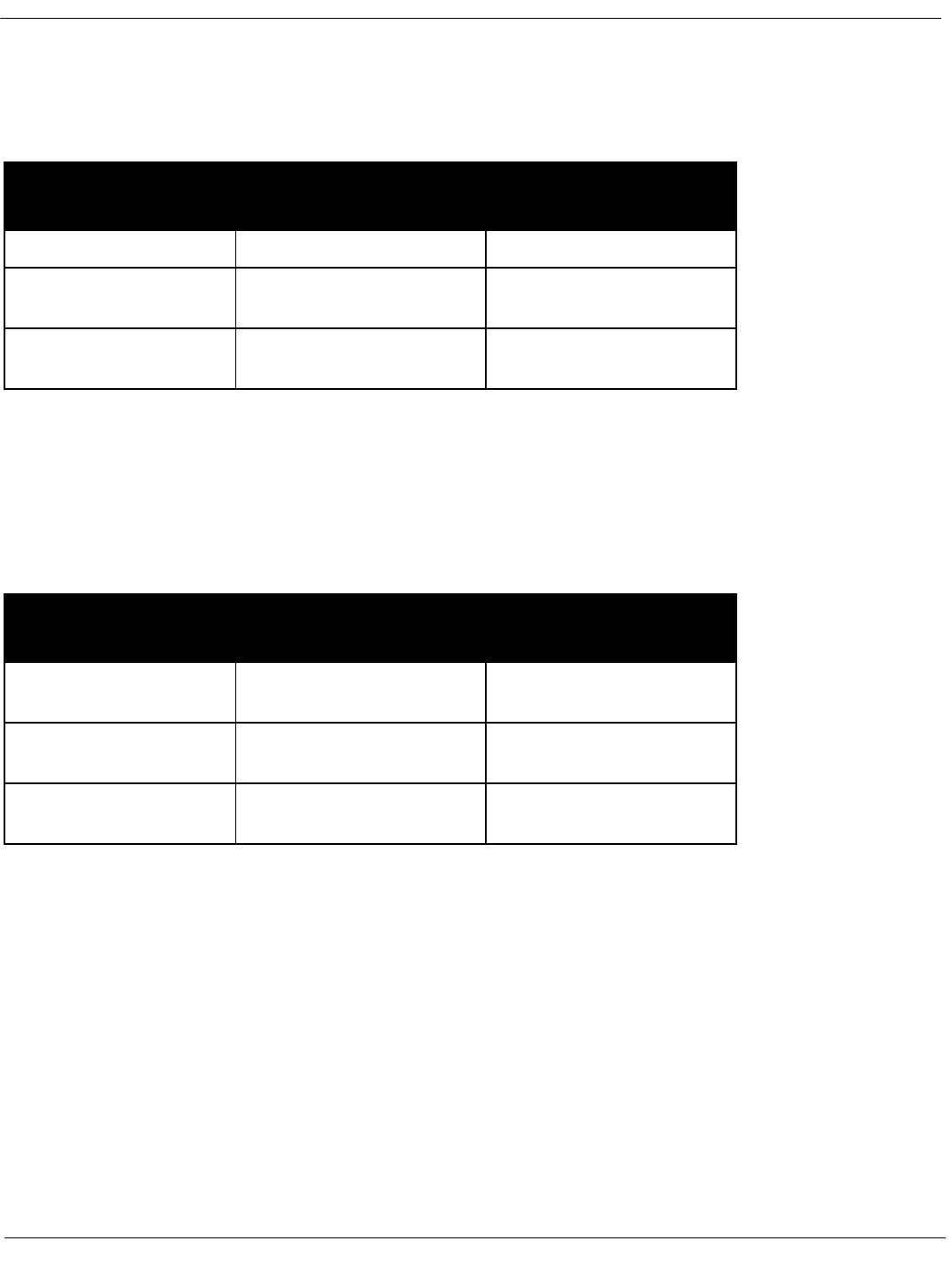
Chapter 13: Related Work
Copyright 2001 Addison Wesley, all rights reserved 313 Draft for review: Do not circulate without permission
The deployment style of the allocation viewtype (described in Section 6.1) is a good match for the RUP deploy-
ment view
.
The Implementation View
The implementation view describes the organization of static software modules such as source code, data files,
etc. The RUP implementation view is best represented using the implementation style of the allocation view-
type.
.
The Use-Case View
The Rational Unified Process describes the use case view as a means to drive discovery and design of software
architecture. This is true no matter which views used to document the architecture. The use-case view cuts
across the other views.
Use case descriptions are included as a vehicle for describing behavior in Chapter 8, and behavior is a part of
every view’s supporting documentation. Consequently, you can document use cases as a behavior description
associated with one or more views.
Table 30: Rational Unified Process Deployment View
Rational Unified Process
term
Our term
Software Components Task Process or component
Environment Compo-
nents
Computers
Network
Physical unit
Physical unit
Relations Communication channel
Executes on
Communication channel
Allocated to
Table 31: Rational Unified Process Implementation View
Rational Unified Process
term
Our term
Software Components Class
Class Category
Module
Module
Environment Compo-
nents
Folders
Files
Configuration item
Configuration item
Relations Aggregation
Realizes
Containment
Allocated to

Documenting Software Architectures Clements, Bachmann, Bass, Garlan, Ivers, LIttle, Nord, Stafford
Copyright 2001 Addison Wesley, all rights reserved 314 Draft for review: Do not circulate without permission
Summary
If you wish to use views prescribed by the Rational Unified Process, you can do so as shown in the following
table:
Furthermore, RUP does not preclude employing additional views that may be useful, and so you are free to
choose any others that can play a helpful role in your project.
Beyond its five views, RUP does not prescribe other kinds of documentation such as interface specifications,
rationale, or behavior of ensembles. It doesn’t call for a view catalog, a mapping between views, view tem-
plates, or style guides. But it certainly does not rule these things out, either.
If you’ve chosen to follow RUP, you can certainly document the five prescribed views using viewtypes and styles
in this book. But don’t stop there. You are also free to consider additional views that may be important in your
project’s context, and you should do so. You should also augment the primary presentation of each view with
the supporting documentation called for in Section 10.1 ("Documenting a view"), and you should complete the
package by writing the documentation that applies across views, as described in Section 10.2 ("Documentation
across views").
The result will be RUP-compliant set of documentation that has the necessary supporting information to make
the whole package complete.
13.3 Siemens Four Views
The Siemens approach to architecture design documents a system using four views. The four views and their
associated design tasks are shown in the figure. The first task for each view is global analysis. In global anal-
ysis, you identify the factors that influence the architecture and analyze them to derive strategies for designing
the architecture. This provides supporting documentation for analysis of the factors that influence the architec-
ture and the rationale for why the design decisions reflected in the view where made [cross ref: Global Analysis
sidebar].
Table 32: Reconciling RUP with the advice in this book
To achieve this RUP
view...
...use this approach
Logical view Employ a module-based style that shows generalization,
uses, and decomposition
Process view Employ the communicating process style of C&C viewtype
Deployment view Employ the deployment style of the allocation viewtype
Implementation view Employ the implementation style of the allocation viewtype
Use case view Use cases to specify behavior, either associated with any
of the views or as part of the documentation across views.

Chapter 13: Related Work
Copyright 2001 Addison Wesley, all rights reserved 315 Draft for review: Do not circulate without permission
The second and third group of tasks are the central and final design tasks. These define the elements of the
architecture view, the relationships among them, and important properties.
The conceptual architecture view describes how the system’s functionality is mapped to components and con-
nectors. This view is closest to the application domain because it is the least constrained by the software and
hardware platforms.
Organizational Factors
Technological Factors
Product Factors
feedback
feed-
forward
Final Design Task:
resource budgeting
Central Design Tasks:
conceptual components
conceptual connectors
conceptual configuration
global evaluation
Conceptual View
Global Analysis:
analyze factors
develop strategies
Central Design Tasks:
source components
intermediate components
deployment components
global evaluation
Final Design Tasks:
build script design
configuration
management design
Code View
Global Analysis:
analyze factors
develop strategies
Global Analysis:
analyze factors
develop strategies
Central Design Tasks:
run-time entities
communication paths
execution configuration
global evaluation
Final Design Task:
resource allocation
Execution View
Final Design Task:
interface design
Central Design Tasks:
modules
layers
global evaluation
Module View
Global Analysis:
analyze factors
develop strategies
HARDWARE ARCHITECTURE
SOURCE CODE
Figure 77: The Four Views of Software Architecture
Source: Applied Software Architecture [redraw with less detail]

Documenting Software Architectures Clements, Bachmann, Bass, Garlan, Ivers, LIttle, Nord, Stafford
Copyright 2001 Addison Wesley, all rights reserved 316 Draft for review: Do not circulate without permission
This corresponds very closely to the Components and Connectors (C&C) viewtype. Components and connec-
tors have an expressive notion of interface (ports and roles respectively).
The module architecture view describes how the components, connectors, ports, and roles are mapped to ab-
stract modules and their interfaces. The system is decomposed into modules and subsystems. A module can
also be assigned to a layer, which then constrains its dependencies on other modules.
Table 33: Siemens Four Views Conceptual Architecture View
Siemens Our term
Elements CComponent
CPort
CConnector
CRole
Protocol
component
port (property)
connector
role (property)
protocol (property)
Relations composition
cbinding
cconnection
obeys
obeys congugate
attachment
Primary
Presentation
Artifacts
Conceptual configuration
Port or role protocol
Component or connector behavior
Interactions among components

Chapter 13: Related Work
Copyright 2001 Addison Wesley, all rights reserved 317 Draft for review: Do not circulate without permission
The module architecture view corresponds to the styles in the module viewtype.
The execution architecture view describes how the system’s functionality is mapped to runtime platform ele-
ments such as processes, shared libraries, etc. Platform elements consume platform resources that are as-
signed to a hardware resource.
This corresponds to the ? viewtype. Other platform elements besides process are supported such as: thread,
task, queue, shared memory, DLL, process, socket, file, shared library. There is limited interface/communica-
tion information. The runtime entities communicate over a communication that uses a mechanism such as IPC,
Table 34: Siemens Four Views Module Architecture View
Siemens Our term
Elements Module
Interface
Subsystem
Layer
module
interface
subsystem
layer
Relations contain
composition
use
require
provide
implement (module - C&C
assigned to (module - layer)
aggregation
decomposition
uses, allowed to use
property of layer
Primary
Presentation
Artifacts
Conceptual-module correspondence
Subsystem and module decomposition
Module use-dependencies
Layer use-dependencies, modules assigned to layers
Summary of module relations
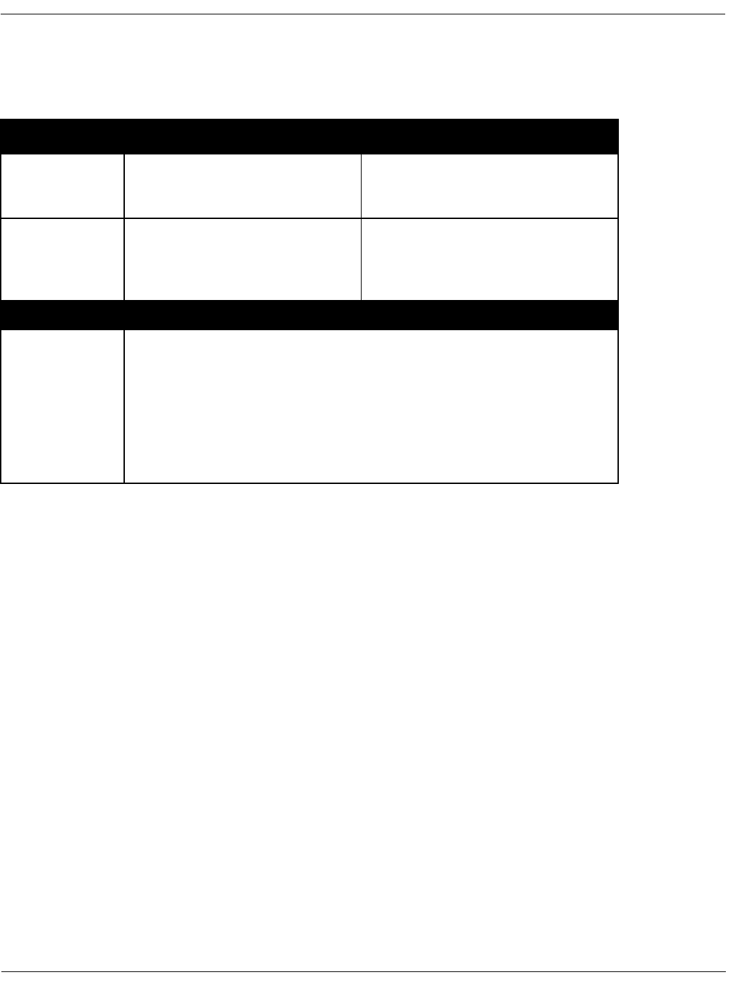
Documenting Software Architectures Clements, Bachmann, Bass, Garlan, Ivers, LIttle, Nord, Stafford
Copyright 2001 Addison Wesley, all rights reserved 318 Draft for review: Do not circulate without permission
RPC, or DCOM. The execution view doesn’t duplicate information from the module view. Communication is de-
rived from hybrid views that combine modules with processes.
The code architecture view describes how the software implementing the system is organized into source and
deployment components.
Table 35: Siemens Four Views Execution Architecture View
Siemens Our term
Elements Runtime entity
Communication Path
concurrent units (process, thread)
communication (data exchange,
control)
Relations use mechanism
communicate over
assigned to (module - runtime
entity)
attachment
Primary
Presentation
Artifacts
Execution configuration
Execution configurationmapped to hardware devices
Dynamic behavior of configuration, or transistion between configura-
tions
Description of runtime entities (including host type, replication, and
assigned modules)
Description of runtime instances (including resource allocation)
Communication protocol

Chapter 13: Related Work
Copyright 2001 Addison Wesley, all rights reserved 319 Draft for review: Do not circulate without permission
This corresponds to the implementation style of the allocation viewtype. The implementation style defines pack-
aging units such as files and directories. Code elements for source, intermediate, and deployment components
are represented as a mapping from modules to files.
Table 36: Siemens Four Views Code Architecture View
Siemens Our term
Elements Source component
Binary component
Library
Executable
Configuration description
Code group
Relations generate
import
compile
link
use at runtime
trace (source comp - module)
instantiate (executable - process)
Primary
Presentation
Artifacts
Module view, source component correspondence
Runtime entity, executable correspondence
Description of components in code architecture view, their organization,
and their dependencies
Description of build procedures
Description of release schedules for modules and corresponding com-
ponent versions
Configuration management views for developers

Documenting Software Architectures Clements, Bachmann, Bass, Garlan, Ivers, LIttle, Nord, Stafford
Copyright 2001 Addison Wesley, all rights reserved 320 Draft for review: Do not circulate without permission
Summary
If you wish to use views prescribed by the Siemens Four Views approach, you can do so as shown in the fol-
lowing table.
Like RUP, the Siemens Four Views approach does not preclude additional information, and so you are free to
(and should) consider what other views may be helpful to your project. And, like RUP, these views form the
kernel of the architecture only; you should complete the package by adding the supporting documentation for
each view, and the documentation across views, both as discussed in Chapter 10.
13.4 C4ISR Architecture Framework
Introduction
The United States Department of Defense (DoD) has defined a framework for architecture development, pre-
sentation, and integration to be used across the military services and defense agencies. This framework de-
fines a coordinated approach for the Command, Control, Computers, Communication, Intelligence,
Surveillance, and ReConnaissance (C4ISR) military domains. The intent of the C4ISR Architecture Framework
is to promote interoperable, integrated, and cost-effective computer-bases systems within and across DoD or-
ganizations. This framework is becoming the required method for the description of information systems within
the DoD, and it is also being adopted and mandated by several other US government agencies.
The motivation for the development of this framework was that there has been no common approach for archi-
tecture development and use within the DoD. The architectures being developed by the various DoD organiza-
tions are significantly different in content and format, and this leads to the development of fielded products
which are not interoperable. These differences are also prohibit useful comparisons and contrasting when an-
alyzing the various architectures. The C4ISR Architecture Framework is intended to provide a common lingua
franca for the various DoD commands, services, and agencies to describe their diverse architectures. This is
intended to help with cross-system analysis and fielded system interoperability.
The framework differentiates between an architecture description
and an architecture implementation. An ar-
chitecture description is a representation of the parts, what those parts do, how they relate to each other, and
Table 37: Reconciling Siemens Four Views with the advice in this book
To achieve this Siemends
Four Views view...
...use this approach
Conceptual architecture One or more styles in the C&C viewtype
Module architecture One or more styles in the module viewtype
Execution architecture Deployment style in the allocation viewtype. For processes,
use cooperating process style in the C&C viewtype.
Code architecture Implementation style in the allocation viewtype

Chapter 13: Related Work
Copyright 2001 Addison Wesley, all rights reserved 321 Draft for review: Do not circulate without permission
under what rules and constraints. The C4ISR Framework is only concerned with this representation and not the
actual implementation in the field. This is the major difference between the C4ISR Framework and the thrust of
this book.
The C4ISR Architecture Framework has the following main components:
• definition of common architectural views
• guidance for developing the architecture
• definition of common products
• relevant reference resources.
Our interest here is in the common views prescribed by the framework.
Common Architectural Views of the C4ISR Framework
The C4ISR Architecture Framework defines three views (operational, system, and technical). The views can
be summarized as:
1. The
operational architecture view is a description of the tasks and activities, operational elements, and in-
formation flows required to accomplish or support operations. It defines the types of information ex-
changed, the frequency of exchange, which tasks and activities are supported by the information exchang-
es, and the nature of the information exchanges in enough detail to ascertain the relevant interoperability
requirements.
2. The
systems architecture view is a description of systems and interconnections providing for and support-
ing the relevant requirements. This view associates physical resources and their performance attributes to
the operational view and its requirements per criteria defined in the technical architecture.
3. The
technical architecture view is a minimal set of rules governing the arrangements, interaction, and in-
terdependence of system parts. This view articulates the criteria that describes compliant implementations
of the various system capabilities.
To be consistent and integrated, an architecture description must provide explicit linkages among its views. This
linkage is provided by the framework products.
Common Products
All the necessary C4ISR architecture representation products are defined by the framework which contains de-
tailed descriptions of the product types that must be used to describe operational, systems, and technical ar-
chitecture views. In many cases, representation formats, product templates and examples are also provided.
The architecture products to be developed are classified into two categories:
• Essential Products: constitute the minimal set of products required to develop architectures that can be
commonly understood and integrated within and across DoD organizational boundaries and between
DoD and multi-national elements. These products must be developed for all architectures.
• Supporting Products: provide data that will be needed depending on the purpose and objectives of a
specific architecture effort. Appropriate products from the supporting product set will be developed
depending on the purpose and objectives of the architecture

Documenting Software Architectures Clements, Bachmann, Bass, Garlan, Ivers, LIttle, Nord, Stafford
Copyright 2001 Addison Wesley, all rights reserved 322 Draft for review: Do not circulate without permission
Table 38 and Table 39 contain a summary of the essential and supporting products, respectively, defined by the
C4ISR Architecture Framework.
Table 38: C4ISR Architecture Framework Essential
Products
Architecture Product
C4ISR
Architecture
View
Overview and Summary Information
All views
Integrated Dictionary All views
High-level Operational Concept Graphic
Operational
Operational Node Connectivity Description Operational
Operational Information Exchange Matrix Operational
System Interface Description Systems
Technical Architecture Profile Technical
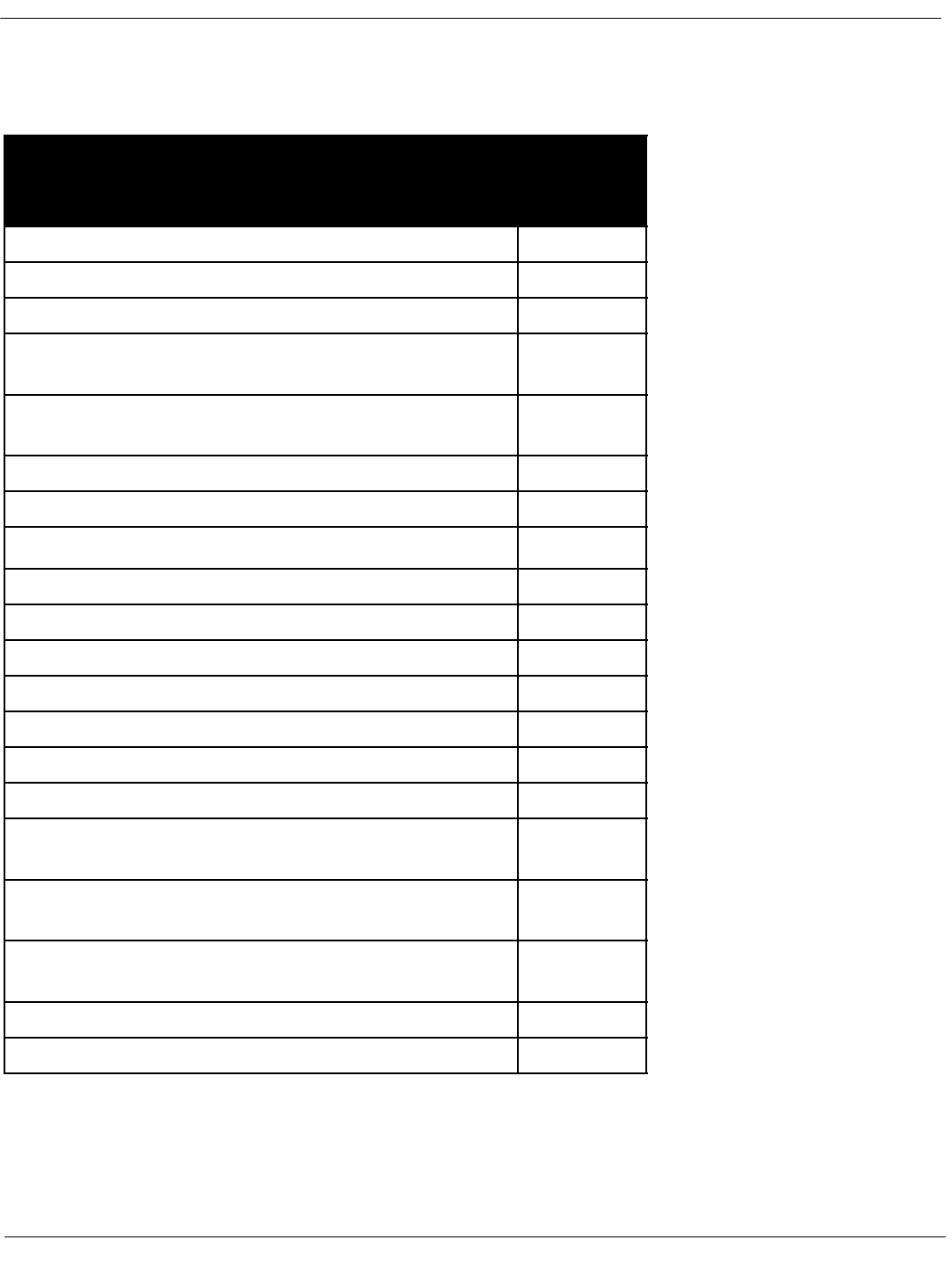
Chapter 13: Related Work
Copyright 2001 Addison Wesley, all rights reserved 323 Draft for review: Do not circulate without permission
It must be said that C4ISR, for all its attention to architecture, in fact is directed almost exclusively to document-
ing
system architecture. None of its three views and none of its essential or supporting products prescribe any-
thing that remotely resembles
software architecture. The operational architecture speaks in terms of user-
visible operations. The system architecture addresses how those operations are carried out on physical re-
Table 39: C4ISR Architecture Framework Supporting Products
Architecture Product
C4ISR
Architecture
View
Command Relationships Chart Operational
Activity Model Operational
Operational Activity Sequence and Timing Descriptions Operational
Operational Activity Sequence and Timing Descriptions --
Operational State Transition Description
Operational
Operational Activity Sequence and Timing Descriptions –
Operational Event/Trace Description
Operational
Logical Data Model Operational
Systems Communications Description Systems
Systems
2
Matrix
Systems
Systems Functionality Description Systems
Operational Activity to System Function Traceability Matrix Systems
System Information Exchange Matrix Systems
System Performance Parameters Matrix Systems
System Evolution Description Systems
System Technology Forecast Systems
System Activity Sequence and Timing Descriptions Systems
Systems Activity Sequence and Timing Descriptions --
Systems Rules Model
Systems
Systems Activity Sequence and Timing Descriptions --
Systems State Transition Description
Systems
Systems Activity Sequence and Timing Descriptions --
Systems Event/Trace Description
Systems
Physical Data Model Systems
Standards Technology Forecast Technical

Documenting Software Architectures Clements, Bachmann, Bass, Garlan, Ivers, LIttle, Nord, Stafford
Copyright 2001 Addison Wesley, all rights reserved 324 Draft for review: Do not circulate without permission
sources (read: hardware). And the technical architecture imposes rules and constraints, which in practice has
come to mean the selection of a set of interface standards and nothing more. Nowhere is the software for the
system described in terms of its structure, or the behavior and inter-relationships of the elements of that struc-
ture.
That said, however, If you’re mandated to use C4ISR, there are options at your disposal.
The first is to recognize the difference between software and system architecture, and to recognize that a soft-
ware-intensive system needs documentation for both. Render unto C4ISR what is C4ISR’s, and provide docu-
mentation for the software architecture (using the guidance of this book) separately.
The second option is to work the documentation for the software architecture into the framework prescribed by
C4ISR. This is Plan B for sure, but serves in the case where management (having been told to adopt C4ISR)
balks at learning something separate is needed for the software aspects. In that case:
[This list is tbd]
• As part of the operational architecture view, include what is essentially a RUP use-case view of the
software.
• As part of the system’s system architecture view...
• As part of the system’s technical architecture view...
• [make sure all our prescriptions -- interfaces, behavior, mappings, etc. -- are accounted for]
13.5 IEEE Standard 1471 on Architecture Documentation
tbd
13.6 Hewlett Packard
tbd
Background
ADLs
Under the heading of “Related Work” it would be hard to ignore a large body of work associated with the
formal representation of software and system architecutres.
A number of researchers in industry and academia have proposed formal notations for representing and
analyzing architectural designs. Generically referred to as ``Architecture Description Languages'' or “Ar-
chitecture Definition Languages” (ADLs), these notations usually provide both a conceptual framework
and a concrete syntax for characterizing software architectures. They also typically provide tools for pars-

Chapter 13: Related Work
Copyright 2001 Addison Wesley, all rights reserved 325 Draft for review: Do not circulate without permission
ing, unparsing, displaying, compiling, analyzing, or simulating architectural descriptions written in their as-
sociated language
Examples of ADLs include Acme [AcmePaper}, Aesop [Garlan94Aesop}, Adage [Coglianese93Adage},
C2 [Medvidovic95FSE4}, Darwin [Magee95ESEC}, Rapide [Luckham95TSE}, SADL [MQR95TSE}, Uni-
Con [Shaw95Unicon}, Meta-H [Binns93}, and Wright~ Allen97TOSEM}.
While all of these languages are concerned with architectural design, each provides certain distinctive ca-
pabilities. For example: Acme supports the definition of new architectural styles; Adage supports the de-
scription of architectural frameworks for avionics navigation and guidance; Aesop supports the use of
architectural styles; C2 supports the description of user interface systems using an event-based style;
Darwin supports the analysis of distributed message-passing systems; Meta-H provides guidance for de-
signers of real-time avionics control software; Rapide allows architectural designs to be simulated, and
has tools for analyzing the results of those simulations; SADL provides a formal basis for architectural re-
finement; UniCon has a high-level compiler for architectural designs that support a mixture of heteroge-
neous component and connector types; Wright supports the formal specification and analysis of
interactions between architectural components.
No ADL provides the facilities to completely document a software architecture, where “complete” is de-
fined in the context of this book’s prescriptions. But many ADLs provide excellent means for discharging
part of the architect’s documentation obligation. Chapter 8, for instance, covered formal notations for
specifying behavior, and any of several ADLs could be brought to bear in that regards. An ADL that pro-
vides a good means to express rich structure could be used to help render the views’ primary presenta-
tions, with the added bonus that analysis based on that ADL’s capability would then be automatically
placed on the fast track.
Besides their analytical prowess, ADLs have the advantage of enforcing their formal models -- they make
it harder to specify architectures that are internally inconsistent, for example, or ambiguous. Like all lan-
guages, however, this can be helpful or painful depending on how consistent that formal model is with
your needs at the time.
For more information...
ADLs are discussed in Section 4.8 ("Notations for C&C Styles") and in the For Further
Reading section of Chapter 8 ("Documenting Behavior").
|| END SIDEBAR/CALLOUT
13.7 Data Flow and Control Flow Views
For years, data flow and control flow were seen as the primary means to document a software system. While
modern software architecture principles have evolved into the more general study of structures and behavior,
there are still pockets of practice in which these two venerable aspects of software -- data and control -- rule
the day. How do they relate to what we would call a more holistic architecture documentation package?
Data flow views
Data flow views of a system are exemplified by data flow diagrams (DFDs), a concept made famous by the
structured analysis methodologies of the 1970s. [check refs, and write short descsription of DFDs.]
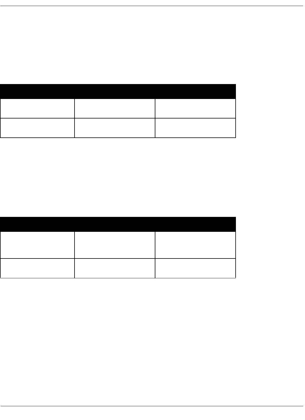
Documenting Software Architectures Clements, Bachmann, Bass, Garlan, Ivers, LIttle, Nord, Stafford
Copyright 2001 Addison Wesley, all rights reserved 326 Draft for review: Do not circulate without permission
If your intent is to represent data flows as described above then the best way to do it is to choose a style in the
C&C viewtype. This viewtype lets you define components for data processing as well as for data stores. A con-
nector in a C&C view describes an interaction or a protocol between components, but usually not the data that
flows across the connector. Therefore, to represent data flow diagrams, define a style of the C&C view type
where the components are procedures (processes) and/or a data stores, and the connector is a “data ex-
change” connector with the additional property of names of data flows.
.
You may also want to describe data flow aspects of modules represented in a style of the module viewtype.
You can show which modules are producers or consumers of a specific data type, to document data type
dependencies.
Representing data flow in a module viewtype is done by defining a style specializing the “depends on” relation
into a “sends data to” relation. In case it is of interest, data stores can be defined as a specialized type of mod-
ule.
Table 40: Representing Data Flow Diagrams Using the C&C Viewtype
Data Flow Diagram term Our term
Components Procedure
Data store
Component (functionality)
Component (data store)
Connectors Data exchange Communication + data
flow name
Table 41: Representing Data Flow Diagrams Using the Module Viewtype
Data Flow Diagram term Our term
Element Procedure
Data store
Module
Specialized module as
data store
Relation Data flow Sends data to specialized
from depends on

Chapter 13: Related Work
Copyright 2001 Addison Wesley, all rights reserved 327 Draft for review: Do not circulate without permission
The allocation viewtype also has the potential to document data flow aspects, especially if analyzing network
or storage capacities is important. Such a diagram would represent how much information flows at a time over
a network connection or how many mega bytes are required for a storage (persistent or temporary)..
Finally, note that DFDs don’t make the strong distinction between modules, components, and hardware plat-
forms that more modern treatments of architecture do. So if your goal is really to reproduce the classic data
flow diagrams structured analysis fame, you may have to define a hybrid style that combines the module, C&C,
and allocation styles discussed above. Data dictionaries, a strong part of DFD methodology, have their coun-
terpart in the element catalogs described in Chapter 10. P-specs, which are essentially pseudo-code represen-
tations of the elements, can be captured as behavioral information in our world.
So if you are a diehard member of the DFD community, take comfort in the fact that you can achieve your goals
with the methods of this book. But heed the advice given for the other representation approaches in this chap-
ter: Augment your favorite with other useful views, and then complete the package by adding supporting doc-
umentation and cross-view documentation.
Observation
“You’re all just guessing!”
The following is a humorous but sobering Socratic dialogue written by Michael Jackson in his book [title] that
reveals the confusion that happens when users of a representation method (Data Flow Diagrams in this case)
are too loose with the definitions of terms used and the underlying semantics implied.
Most of the miscommunication and unintended misdirection (we assume the participants are non-malevolent)
comes from an uncommon (by the various participants) understanding of the definitions of the important terms
used. Each participant has their own understanding of what the fundamental terms mean. Additionally, DFDs
are bereft of any formal mechanisms that allow the designer to record unambiguous semantic information.
While a common and agreed upon data dictionary (as recommended by DFD advocates) would go a long way
to alleviate many of the problems illustrated in this example, DFDs still do not have the semantic rigor to do
more that present a cartoonish view of a system.
Table 42: Representing Data Flow Diagrams Using the Allocation Viewtype
Data Flow Diagram term Our term
Software Element Procedure
Data store
process
Specialized module as
data store
Environmental Element Processor
Data storage
Physical unit (data store)
Physical unit (processor)
Relation Data flow
Communication channel
Sends data to
Communication

Documenting Software Architectures Clements, Bachmann, Bass, Garlan, Ivers, LIttle, Nord, Stafford
Copyright 2001 Addison Wesley, all rights reserved 328 Draft for review: Do not circulate without permission
While this example might appear to be contrived, these lessons generalize. The authors have experienced sim-
ilar situations in many different settings and with many different representation techniques and methods. The
DFD notation is not the only one that suffers from these problems and misuses.
They were all ready to start the walkthrough. Fred had been working on part of the sales accounting sys-
tem: the problem of matching customers’ payments to their outstanding invoices. He had produced a data-
flow diagram, and was going to walk through it with Ann and Bill. Jane was there too, because she was
new to the team and didn’t know about dataflow diagrams. This was a good opportunity for her to learn
about them. Fred had invited her, and the project manager said it was a good idea.
‘The diagram I’m going to show you,’ said Fred, ‘expands a process bubble in the diagram at the next level
up. Here’s the bubble to be expanded.’ He showed this viewgraph on the overhead projector:
[figure]
‘The payments come in from customers – that’s the arrow on the left. Basically, we have to send the pay-
ment details to the cashiers for banking – that’s the arrow on the right – and put a payment record into the
Receivables file on the top right. To do that, we must match the payments with invoices that we get from
the Receivables file. If we can’t match a payment we put it into the Untraced Payments file, and someone
else deals with it. If the payment is not enough to cover the amount in the invoice we send the customer
a request to pay in full – that’s up at the top left. Oh, and we also send them requests to explain untraced
payments. OK so far?’
‘I suppose you need the Customer file so you can put names and addresses on the payment and expla-
nation requests,’ said Ann.
‘Right,’ said Fred. ‘Now here’s the diagram I’ve done that expands the process bubble.’ He put another
viewgraph on the projector. It was this:
[figure]
‘Looks good,’ said Bill. ‘Let me see if I can walk through it. The Verify Payments process checks to see
whether a payment has an invoice number. If it has, you find the invoice – that’s the Find Invoice by No
process at the top of the diagram – and send it with the payment to the Compare Amount process. If it
hasn’t, you have to search for the invoice by using the customer’s name and the amount of the payment.
If that doesn’t work you have an untraced payment. Otherwise you send the invoice and payment details
to the Compare Amount process as before. Am I on the right lines?’
‘Absolutely,’ said Fred. ‘Right on.’
‘The Compare Amount process checks the amount paid against the invoice, and whether it’s a full or a
part payment you send the details to the cashier for banking and put a payment record in the Receivables
file. If it’s a part payment you also produce a full payment request. Am I right, or am I right?’
‘Terrific,’ said Fred. ‘You just forgot to say that untraced payments go to the Produce Explanation Request
process so we can send a request to the customer.’
‘Sounds good to me,’ said Ann. ‘We could have an early lunch.’
‘Well, wait a minute,’ said Jane. ‘I haven’t really understood what’s going on. You said that Verify Pay-
ments sends each payment either to Find Invoice by No, or to Search for Invoice, depending on whether
it has an invoice number or not. Where does it say that in the diagram?’
‘Verify Payments has one input data flow and two outputs,’ said Ann. ‘That’s where it says it. It’s just like
the Search for Invoice process. That’s got one input data flow of payments without invoice numbers, and
two output flows, one for untraced payments, and one for payments with invoices.’
‘But the Create Payment Record process also has two output flows,’ said Jane, ‘one for payment records
for the Receivables file, and one for payment details for the bank. But it sends each full or part payment
to both of those, not just to one.’
‘Ann’s a bit confused,’ said Bill. ‘A dataflow diagram doesn’t show whether a process writes to one or more
of its output flows for each input message. That’s at a lower level, probably in the process specification.
It’s a top-down technique.’
‘I’m not at all confused,’ said Ann. ‘It just depends on your conventions. And I know about top-down as
well as you do.’

Chapter 13: Related Work
Copyright 2001 Addison Wesley, all rights reserved 329 Draft for review: Do not circulate without permission
‘All right,’ said Jane. ‘So we’re using Bill’s convention. So how do you know that Verify Payments never
writes on both its output data flows?’
‘That’s a funny question,’ said Fred. ‘It’s obvious, because one flow is named Payment Quoting Invoice
No and the other one is Payment Without Invoice No. You have to read the names. Names are very im-
portant in systems analysis.’
‘I am reading the names,’ said Jane, ‘and I don’t understand them at all. For example, does “Full Payment”
mean the exactly right amount has been paid, or does it include overpayments? And does “Invoice and
Payment Details” mean exactly one invoice and one payment? Don’t customers sometimes send one pay-
ment to cover more than one invoice? And they could send two cheques to cover one invoice, I suppose,
as well, couldn’t they? And then, what’s this Search for Invoice process doing? Suppose there are two
invoices for the customer, both with the same amount as the payment? Or two invoices adding up to the
amount of the payment? Does “Search for Invoice” mean it’s only searching for one invoice? Or suppose
it finds just one invoice, but it’s less than the payment? I don’t see how you can work out from the diagram
whether these are real possibilities, and, if so, what’s supposed to happen when they turn up.’
‘Look, Bill’s already said it’s top-down,’ said Fred, ‘so you can’t expect to answer all these detailed ques-
tions now. You’ll have to come along to the next walkthrough when I’ll have the next level of dataflow di-
agrams for the more complicated processes here – probably for Search for Invoice and Compare Amount
– and process specifications for the rest.’
‘But I don’t think these are detailed questions,’ said Jane. ‘The problem is matching payments to invoices,
and you’re telling me that the diagram doesn’t show whether the matching is one-to-one, one-to-many,
many-to-one, or many-to-many. I’d have thought that was a fundamental question about a matching prob-
lem, not a detailed question. If the diagram doesn’t show that, what does it show?’
‘Well,’ said Bill, ‘it shows that the function of matching payments to invoices needs seven processes con-
nected by the data flows you can see. That’s what it shows.’
‘I don’t understand,’ said Jane. ‘It seems to me that it just shows that Fred thinks that seven processes
connected like that would be useful. But to find out what the function is, or what the processes are, we
have to wait till the next level. So the diagram shows that Fred thinks seven processes would be good for
the function, but we don’t know what function and we don’t know what processes. That can’t be right, sure-
ly?’
‘Hold on,’ said Fred. ‘We’re going way off track here. The questions Jane is asking about the matching
problem are all good questions, and the whole point of the dataflow diagram is that it makes you think
about the good questions – just like Jane is doing. She’s got the idea pretty fast,’ he said, ingratiatingly.
‘That’s what a walkthrough’s all about.’
‘Nice of you to say so,’ said Jane, ‘but I’m still lost. Suppose we do discuss and think about these ques-
tions, would we be able to show the answers in the diagram? From what everyone’s been saying, we
wouldn’t be able to. We’d have to wait till the next level. But I don’t see how you’d do it at the next level
either. Until you get down to the process specifications you keep talking about. I suppose you could tell
from them what it’s all about, but if there are lots of levels you might have to wait a long time. The dataflow
diagrams in the levels above don’t seem to be much use. They’re just vague pictures suggesting what
someone thinks might be the shape of a system to solve a problem, and no one’s saying what the problem
is.’
‘Jane, that’s offensive,’ said Bill. ‘Everyone uses dataflow diagrams here, and everyone knows that top-
down is the right way to do things. There just isn’t any other way. You have to start with the big picture and
work your way down to the details.’
‘Perhaps,’ said Jane, ‘but the big picture isn’t much use if it doesn’t say anything you can understand.
You’re all just guessing what Fred’s diagram means. It wouldn’t mean anything at all to you if you didn’t
already have a pretty good idea of what the problem is and how to solve it.’
They went to lunch after that. It was a rather uncomfortable lunch. After lunch Bill and Fred were walking
together back to the office they shared. ‘I don’t understand Jane,’ said Fred. ‘No,’ said Bill. ‘I don’t think
we should invite her to the next walkthrough, do you?’

Documenting Software Architectures Clements, Bachmann, Bass, Garlan, Ivers, LIttle, Nord, Stafford
Copyright 2001 Addison Wesley, all rights reserved 330 Draft for review: Do not circulate without permission
|| END SIDEBAR/CALLOUT
Control Flow Views
While a data flow diagram portrays a system from the point of view of the data, the point of view of a control
flow graph is to portray the functionality that performs transformation on the data. An example of a control flow
graph is the venerable flow chart. In the behavior section of this book we introduced several modeling tech-
niques from where some of them have flow chart like control symbols such as decisions and loops (see SDL
diagrams or procedural sequence diagrams). Therefore, if you have flow charts as part of your system docu-
mentation and are looking for a place to put them in a documentation package prescribed by this book, they
can be regarded as a form of behavior description and can be used in conjunction with any viewtype.
In some cases, for example to support performance analysis or to build in an aid for later debugging, a control
flow notation in the primary presentation of a view might be of interest.
In a C&C style, the usage of a specific connector defines a control flow (interaction) between the connected
components.
In a module view type, control flows would be represented as a “uses” relation specialized into “transfers con-
trol” relation.
Table 43: Representing Control Flow Diagrams Using the C&C Viewtype
Control Flow Diagram
term
Our term
Components Procedure Component (process)
Connectors Control flow
Connector
Table 44: Representing Control Flow Diagrams Using the Module Viewtype
Data Flow Diagram term Our term
Element
Procedure (process) Module
Relation
Control flow transfers control to spe-
cialized from uses

Chapter 13: Related Work
Copyright 2001 Addison Wesley, all rights reserved 331 Draft for review: Do not circulate without permission
In a deployment viewtype the change of control in the execution environment can be represented. Performance
analysis, but also security and availability analysis that include the execution platform rely on understanding
the flow of control over the platform.
So classic flowcharts, which detail the behavior of programs, can be used as a way to specify the behavior of
elements, but there are many more suitable techniques available to do that. At coarser levels of granularity,
however, it might make sense to show control flow among architectural elements as a view in its own right, but
be clear on the expected usage of such a view. Views based on other styles might do the same job and convey
richer information as well.
“”
“The flow chart is a most thoroughly oversold piece of program documentation...
The detailed blow-by-blow flow chart... is an absolute nuisance, suitable only for
initiating beginners into algorithmic thinking.”
-- F. P. Brooks, Jr. 1975
13.8 Glossary
•
•
•
Table 45: Representing Control Flow Diagrams Using the Allocation Viewtype
Data Flow Diagram term Our term
Software Element
Procedure (process)
Process
Environmental Element
Physical unit
Relation
Control flow Communication (special-
ized to control flow)

Documenting Software Architectures Clements, Bachmann, Bass, Garlan, Ivers, LIttle, Nord, Stafford
Copyright 2001 Addison Wesley, all rights reserved 332 Draft for review: Do not circulate without permission
13.9 Summary checklist
Advice
13.10For Further Reading
tbd -- see reference list below
13.11Discussion Questions
tbd
13.12References (move to back of book)
tbd
{SG96, author = “Mary Shaw and David Garlan”, title = “Software Architecture: Perspectives on an Emerging
Discipline”, publisher = “Prentice Hall”, year = 1996, key = “Shaw”, isbn = “ISBN 0-13-182957”
@Article{Shaw95Unicon, author = “Mary Shaw and Robert DeLine and Daniel V. Klein and Theodore L. Ross
and David M. Young and Gregory Zelesnik”, title = “Abstractions for Software Architecture and Tools to Support
Them”, key = “Shaw”, journal = “IEEE Transactions on Software Engineering, Special Issue on Software Archi-
tecture”, year = 1995, volume = 21, number = 4, pages = “314-335”, month = “April”
@InCollection{Garlan00AcmeChapter, author = {David Garlan and Robert T. Monroe and David Wile}, title =
{Acme: Architectural Description of Component-Based Systems}, booktitle = {Foundations of Component-
?

Chapter 13: Related Work
Copyright 2001 Addison Wesley, all rights reserved 333 Draft for review: Do not circulate without permission
Based Systems}, key ={garlan}, year = 2000, editor = {Gary T. Leavens and Murali Sitaraman}, publisher =
{Cambridge University Press}, pages = 47-68
@Article{Allen97TOSEM, author = {Robert Allen and David Garlan}, title = {A Formal Basis for Architectural
Connection}, journal = {ACM Transactions on Software Engineering and Methodology}, year = 1997, key =
{Allen}, month = {July}
@InProceedings{Binns93, author = “Pam Binns and Steve Vestal”, title = “Formal Real-Time Architecture
Specification and Analysis”, booktitle = “Tenth IEEE Workshop on Real-Time Operating Systems and Soft-
ware”, year = 1993, address = “New York, NY”, month = “May”}
@Inproceedings{Coglianese93Adage, key=”Coglianese”, author= Coglianese and R. Szymanski”, title=
”{DSSA-ADAGE: An Environment for Architecture-based Avionics Development}”, year= 1993, month=”May”,
booktitle=”Proceedings of AGARD'93”
@inproceedings{Garlan94Aesop, key = “Garlan”, author = “David Garlan and Robert Allen and John Ocker-
bloom”, title = “Exploiting Style in Architectural Design Environments”, booktitle = “Proceedings of SIG-
SOFT'94: The Second ACM SIGSOFT Symposium on the Foundations of Software Engineering”, year =
1994, pages = “179-185”, month = “December”, publisher = “ACM Press”
@Article{Luckham95TSE, author = “David C Luckham and Lary M. Augustin and John J. Kenney and James
Veera and Doug Bryan and Walter Mann”, title = “Specification and Analysis of System Architecture Using
{R}apide”, key = “Luckham”, journal = “IEEE Transactions on Software Engineering, Special Issue on Software
Architecture”, year = 1995, volume = 21, number = 4, pages = “336-355”, month = “April”
@InProceedings{Magee95ESEC, author = “J. Magee and N. Dulay and S. Eisenbach and J. Kramer”, title =
“Specifying Distributed Software Architectures”, key = “Magee”, booktitle = “Proceedings of the Fifth European
Software Engineering Conference, ESEC'95”, year = 1995, month = “September”
@InProceedings{Medvidovic95FSE4, author = {Nenad Medvidovic and Peyman Oreizy and Jason E. Robbins
and Richard N. Taylor}, title = {Using Object-Oriented Typing to Support Architectural Design in the {C2} Style},
booktitle = {SIGSOFT'96: Proceedings of the Fourth ACM Symposium on the Foundations of Software Engi-
neering}, key = {Medvidovic}, year = 1996, publisher = {ACM Press}, month = {October}
Scratch file
The interrelating structure of view packets gives the architect flexibility about how to package the supporting
documentation. For instance, an architect might find it convenient to only provide one catalog, or one glossary,
for the entire view, or even for the entire system, as opposed to a number of smaller ones for each view packet.
Information that applies to all view packets in the view can be included in the supporting documentation for the
view packet at the “root” level of the view’s view packet tree. This packet is a distinguished view packet in that
its scope is the entire system (or at least the entire part whose architecture is being documented).
Thus, an architect can package supporting documentation of a view in one of three ways:

Documenting Software Architectures Clements, Bachmann, Bass, Garlan, Ivers, LIttle, Nord, Stafford
Copyright 2001 Addison Wesley, all rights reserved 334 Draft for review: Do not circulate without permission
• distributing it as appropriate across the view packets, in each case providing only the minimal amount
necessary to explain that packet. This will make the view packets self-explanatory and let them be
distributed to stakeholders independently; however, it may also result in duplication, since the same
elements or glossary terms or rationale may apply to many view packets.
• by gathering it into one place for the entire view, and associating it with the “root” view packet for the
view. This approach minimizes duplication, but may also result in information overload for a stakeholder
who is interested only a small part of the view.
• a combination of the two. For example, some rationale might apply to the portion of a design captured
by a view packet, whereas other rationale might well apply to the entire view. The latter could be
recorded with the “root” packet, with the former captured where it applies.
Advice
Deciding whether to bundle or distribute supporting documentation is a packaging issue. If you have a stakeholder to whom
you would give some (but not all) view packets of a view, then you probably want to make those view packets self-sufficient.
A common example of this is a stakeholder to whom you wish to convey introductory or overview information, but not detailed
design. If you would not expect to distribute view packets in a view separately, then bundling the supporting information in
the “root” packet makes sense.
