PYROLYSIS RATE AND YIELD STRENGTH REDUCTION IN
CARBON FIBER AND GLASS FIBER COMPOSITES UNDER
REENTRY HEATING CONDITIONS
Benton R. Greene
(1)
and Chris L. Ostrom
(2)
(1)
Jacobs JETS Contract, NASA Johnson Space Center, 2101 NASA Pkwy XI5-9E, Houston, TX 77058, USA,
benton.r.greene@nasa.gov
(2)
HX5 Jacobs JETS Contract, NASA Johnson Space Center, 2101 NASA Pkwy XI5-9E, Houston, TX 77058, USA,
christopher.l.ostrom@nasa.gov
*Trade names and trademarks are used in this report for identification only. Their usage does not constitute an official endorsement,
either expressed or implied, by the National Aeronautics and Space Administration
ABSTRACT
The behavior of composite materials, specifically
carbon fiber-reinforced polymer (CFRP) and glass
fiber-reinforced polymer (GFRP), under re-entry
conditions poses a problem for orbital debris re-entry
risk modeling. Since these materials pyrolyze rather
than melt and their different components demise at
different rates, modeling their destruction to determine
ground impact risk is complex. Modern spacecraft are
using these materials in ever-greater quantities owing to
their superior strength-to-weight characteristics, and
this has required that the orbital debris community
improve its understanding of how these materials
demise on re-entry.
In 2019, the NASA Orbital Debris Program Office
(ODPO) undertook an extensive test campaign to better
understand the rate at which several types of GFRP and
CFRP materials pyrolyze under re-entry heating
conditions and how that pyrolysis affects their ultimate
strength. GFRP with a polyester resin (G10/FR-4) and
CFRP with epoxy, cyanate ester, vinyl ester, and
phenolic resins were tested. The test campaign was
carried out at the Inductively Coupled Plasma (ICP)
Torch Facility at the University of Texas at Austin.
Because the ICP facility operates in a shirt-sleeve
environment, test samples can be changed within
seconds or minutes, allowing many samples to be tested
in a short period. Two nominal heat flux rates, 20 W/cm
2
and 30 W/cm
2
, and two oxygen concentration
conditions, 0% and 2% of atmospheric (i.e., 0% and
0.4% absolute oxygen concentration), were applied to
all five types of material. To measure both the char rate
and the effect of pyrolysis on the ultimate strength of the
material, two types of tests were carried out for each
material: a char rate test on a ~10 mm-thick sample of
material and an in-situ bending stress test of a ~2 mm-
thick sample of material.
Measurements of the char rate showed very similar
average pyrolysis front velocity in epoxy resin CFRP as
in G10 at 3.6 mm/min and 3.4 mm/min, respectively.
However, the total mass loss rate in the G10 was nearly
double that of the CFRP at 3.8 g/min and 2.2 g/min,
respectively. This result represented a slow ablation rate
of carbon fibers in the CFRP at the temperatures
encountered in low Earth orbit re-entry and a
comparatively rapid removal of the glass fibers in G10
due to melting and spallation. Pyrolysis front velocity
was more significantly affected by the type of polymer
than the type of fiber, with the cyanate ester CFRP
samples displaying an average pyrolysis front velocity
of only 1.9 mm/min.
Similarly, the effect of thermal exposure on the ultimate
strength of the material depended heavily on the type of
polymer and very little on the type of fiber in the
material. Epoxy, vinyl ester, and polyester resins all
behaved very similarly, with complete structural failure
at between 400 J/g and 600 J/g of specific absorbed heat.
Phenolic and cyanate ester resins, on the other hand,
displayed a change in structural properties that was only
barely measurable with the current apparatus even after
the maximum exposure time tested.
These data are being incorporated into a numerical
model of the ablation and demise of composite materials
that will be used to more accurately calculate the ground
casualty risk of future spacecraft.
1 Introduction
Atmospheric re-entry of orbital debris has been a
problem since the very first orbiting spacecraft was
launched and has been studied throughout the history of
space flight. Today, proposed spacecraft must
demonstrate through re-entry simulations that any
debris that might survive atmospheric re-entry has less
than a 1:10,000 probability of causing any human
casualty. One of the NASA Orbital Debris Program
Office (ODPO) tasks is to maintain tools to assess this
re-entry risk and advise space operators on safety best
practices.
Changing trends in the materials used for spacecraft
design have necessitated updating the assumptions used
in modeling spacecraft re-entry and breakup to account
for the differences in the response of new materials to
extreme temperatures.
1.1 Current Modeling Approach
For spacecraft that use traditional materials such as
aluminum, steel, titanium, and even gallium arsenide in
solar panels, aerothermal demise can be modeled as a
straightforward calculation of aerodynamic heat
absorbed vs. that needed to cause the material to melt or
vaporize. However, for newer materials like glass fiber-
and carbon fiber-reinforced polymers (GFRP and
CFRP, respectively), the calculation is not so simple.
Fiber-reinforced polymer (FRP) composites respond
very differently to the elevated temperatures of re-entry.
Rather than melting, the polymer matrix pyrolyzes and
forms a char layer that can insulate deeper material from
the elevated temperature and may continue to hold the
fiber strands together. Even if most of the matrix is
burned away, the pure carbon fibers can maintain their
strength up to 3,000 K. Depending on how the fibers are
interwoven, this may prevent aerodynamic forces from
shredding the remaining fibers into harmless wisps of
material.
Until recently, all of these potential problems were
assumed to be negligible, and fiber-reinforced polymers
were considered to demise when the material reached
the glass transition temperature or the char temperature
of the matrix material. Once the matrix material reached
this point, it was assumed that the reinforcing fibers
would be more or less immediately shredded by
aerodynamic forces. The discovery of composite
overwrapped pressure vessel (COPV) style tanks
surviving intact to the ground [1], as well as a study of
the demisability of COPVs performed by Hyperschall
Technologie Göttingen (HTG) [2], began to sow doubt
about the validity of this assumption.
1.2 Modeling FRPs
It is clear that the current approach is insufficient to
produce results of the required fidelity and a new
approach is needed that accounts for the charring
properties of the matrix and the weave and composition
of the fibers. The fidelity of this model must balance the
risk assessment accuracy against the need for rapid
calculations.
An appropriate model for re-entering FRP components
approximates the pyrolysis process for a given matrix
material and determines rate of char formation in a
component, the amount of residual material in the
charred matrix, and the degree to which that residual
material still holds the fibers together. It also needs to
model the ablation, melting, or vaporization of the fiber
material. If the fiber material does not demise, the model
needs to account for the aerodynamic shear force
necessary to remove the exposed fibers from the
material surface.
Despite the increasing amount of FRP materials being
used on spacecraft, very little published work is
available for how such materials behave in the re-entry
environment. One-dimensional heat transfer through a
charring graphite epoxy composite was investigated as
far back as 1980 using a continuous wave CO
2
laser
energy source to produce surface heat fluxes of up to
2.79 kW/cm
2
[3]. There is, however, a large body of
work on the behavior of composites in a fire
environment, which is analogous though with a much
lower typical heat flux. Some of this work is
summarized by Blasi [4] and in Chapter 8 of Composite
Materials [5].
A very simple model for mass loss rate from charring
graphite epoxy, for example, was presented by Hidalgo,
et al., which uses results from thermogravimetric
analysis (TGA) of the given material [6]. However, this
model was only validated with samples being exposed
to a heat flux rate of 3 W/cm
2
, an order of magnitude
lower than that typical of low Earth orbit (LEO)
atmospheric re-entry. McKinnon, et al., measured the
changes in thermal transport properties as a composite
undergoes pyrolysis using a combination of modeling
and a series of experimental procedures [7]. Other
researchers have studied graphite epoxy degradation
under heat fluxes up to 7.5 W/cm
2
[8] [9] [10] and one
up to 18 W/cm
2
[11].
Understanding the residual strength of charred
composite materials both during and after heating is also
essential to a good model of component demise on
re-entry. This will help determine the breakup of larger
assemblies into smaller components as well as the
aerodynamic shear force necessary to shred exposed
fibers. Once again, some direction in this area can be
found in the fire sciences, where many researchers have
experimentally investigated the change in structural
properties of graphite epoxy composites under extreme
heat conditions [12] [13] [14] [15].
1.3 Results of Phase I
The NASA ODPO conducted a Phase I Re-entry
Survivability Test Campaign study in March 2018 to
acquire preliminary data on how CFRP and GFRP
materials respond to re-entry conditions [1]. In these
tests, many of the CFRP samples took longer to demise
than the typical duration of aerodynamic heating during
re-entry. Reference [1] contains a full description of the
tests and analysis of the results.

In those tests, cylindrical samples of GFRP, CFRP, and
Kevlar® fiber-reinforced polymer (manufactured by
E.I. du Pont de Nemours and Co.), were exposed to
atmospheric re-entry temperatures and the time required
for complete destruction of the material was measured.
While the Kevlar fiber demised very quickly, the GFRP
and CFRP took several minutes to demise, and in the
absence of any oxidative process, the CFRP completely
failed to demise, maintaining some structure even after
5 minutes of exposure. These results prompted an
update to the NASA re-entry prediction models: the
Object Reentry Survival Analysis Tool (ORSAT) and
the Debris Assessment Software (DAS) utility. ORSAT
now treats CFRP components as a mixture of an epoxy
matrix that demises readily and a carbon substrate that
survives nearly intact, and DAS assumes that all CFRP
materials will survive [1].
The current ORSAT and DAS models, while believed
by the ODPO to be appropriately conservative given the
current state of understanding, are not a complete
depiction of the re-entry demisability of FRP materials.
More information is needed to understand how a high-
temperature, high-shear stress environment degrades
and eventually destroys these materials.
2 Experimental Methods
To develop a sufficiently accurate model of FRP re-
entry demise, several gaps in understanding need to be
filled: the rate at which the material chars, the residual
mass of charred matrix material, the residual strength of
the charred matrix, and the degree to which the fibers
interlocking in a weave pattern resist shredding by
aerodynamic shear. Phase II of the ODPO’s Re-entry
Survivability Test Campaign is designed to address the
first three of these knowledge gaps.
As discussed in the Phase I paper, CFRP appears to be
the least demisable of the FRP materials tested, so Phase
II focuses on this material, though G10 fiberglass is also
studied, as it is a very common material in printed circuit
boards. The results need to be broadly generalizable, so
several varieties of resin matrix are studied at different
oxygen and heat fluxes.
The tests conducted in Phase II are designed to answer
the following questions for as many resin matrices and
at as many relevant conditions as possible:
• At what rate does the resin pyrolysis front
travel through the virgin material, and how is
this rate affected by the heat flux, resin type,
and thickness of unremoved char material?
• How much residual char remains after the resin
has completely pyrolyzed?
• How is the structural strength of the material
degraded with temperature, char progression,
and ablation?
• Once a partially charred FRP cools, what is the
residual structural strength of the remaining
mixture of virgin and charred material?
Three tests were devised to answer these questions:
• Char Rate – Expose a sample coupon to a
plasma flow for varying amounts of time and
measure the total mass lost and the depth of
charred material at the end of each time span.
During exposure, measure the stagnation point
temperature and backside temperature of the
sample.
• In-Situ Strength – Expose a sample to a plasma
flow while applying a constant 4-point bending
load and measure the stagnation point
temperature, backside temperature, and strain
of the sample throughout exposure.
• Residual Strength – Expose a sample to plasma
flow under unloaded conditions for varying
lengths of time. Measure stagnation point and
backside temperature during exposure. After
returning to room temperature, load the sample
in a 4-point bend and measure load, strain, and
ultimate strength of the partially charred
sample.
2.1 Plasma Torch Facility
The Inductively Coupled Plasma (ICP) facility is in the
University of Texas at Austin Wind Tunnel Labs and
consists of a 50 kW inductively coupled plasma
generator, pictured in Fig. 1. The facility operates at
room pressure and provides easy access for changing
test samples and instrument probes. Room pressure
operation also allows for excellent optical access for
many remote measurements like optical pyrometers and
video cameras. The torch itself can generate plasma
streams of argon or air plasma at flow rates up to 80
slpm and temperatures up to 7,000 K for air and 10,000
K for argon [16]. The diameter of the plasma plume is
30 mm.
Figure 1. ICP in operation
Sting Arms
Plasma Plume

The facility provides two water-cooled, motorized sting
arms, also shown in Fig. 1, for mounting test samples
and instrument probes. The water-cooling allows the
probe or sample to be inserted into the plasma stream for
an indefinite period.
2.2 Test Samples
Over 230 individual samples were tested in this
campaign to maximize the number of tests, conditions,
and repeated data points. Because so many samples
needed testing, the shape of the test samples was chosen
to minimize the time to change out samples between
tests and to minimize complexity of the test sample
holder.
All test samples were cut to be the same planform size
rectangular coupon. The rectangular coupon shape
allowed a 4-point bending load to be easily applied to
the sample during exposure to the plasma using a simple
set of counterweighted jaws. This same set of
counterweighted jaws could be used to hold all of the
other samples not being placed under load by simply
changing the offset of the lower jaws from the upper
one.
Two basic sample shapes were used: a 7- to 10-mm-
thick rectangular coupon for the char/ablation rate tests
and a 1- to 3-mm-thick rectangular coupon, for the static
loading tests. All of the coupons were 80 ± 0.7 mm long
by 25 ± 0.2 mm wide. The exact thickness of the coupon
depended on the available stock of the given material.
Of the several materials used in the test campaign, two
materials were exposed to every test condition: the
DragonPlate® Economy Plate carbon fiber epoxy panel
and the G10 fiberglass panel. DragonPlate is the
tradename for the engineered carbon fiber composites
made by ALLRed & Associates Inc. under the
DragonPlate® brand. These two materials were chosen
as broadly representative of the two most common types
of composite material aboard spacecraft. Many
structural panels are made of a carbon fiber epoxy
composite, and most circuit boards are made with a G10
or FR-4 fiberglass composite material. Other materials
used were:
• DragonPlate High Temp carbon fiber panel
• CFRP face sheet/Al honeycomb core panel
• Hand layup carbon fiber/vinyl ester resin
composite panel
• Hand layup carbon fiber/epoxy resin
composite panel
• Carbon fiber/cyanate ester resin composite
panel
• Carbon fiber/phenolic resin composite panel
Except for the DragonPlate High Temp panel, these
other composites were manufactured in-house at the
NASA Johnson Space Center (JSC) machine shop. The
cyanate ester resin panel, phenolic resin panel, and the
CFRP/aluminum honeycomb panel were taken from
off-cuts of other projects to incorporate actual
production materials into the test campaign. Tab. 1 gives
the number of samples of each material used for each
test.
Table 1. Quantity of coupons of each material used in
each test
Material
Test
Quantity
DragonPlate
Economy Plate
Char Rate 34
In-Situ Strength 8
Residual Strength 24
G10 Fiberglass
Char Rate
32
In-Situ Strength
8
Residual Strength
24
DragonPlate High
Temp
In-Situ Strength 8
CFRP/Al
honeycomb
Char Rate 2
CFRP – Vinyl
Ester Resin (Hand
Layup)
In-Situ Strength
8
Residual Strength 24
CFRP – Epoxy
Resin (Hand
Layup
In-Situ Strength
8
Residual Strength 24
CFRP – Cyanate
Ester Resin
Char Rate
10
In-Situ Strength
8
Residual Strength
8
CFRP – Phenolic
Resin
Char Rate 8
2.3 Test Setup
Figure 2. Diagram of counterweight bending load
application
The sample coupons were mounted in the counter-
weighted clamp system pictured in Fig. 2. This system
allowed a quick (~10 sec.) installation and removal of
the sample and provided a mechanism for applying a
repeatable 4-point bending load to a sample during the
In-Situ Strength tests.
Due to the varying test coupon thicknesses among the
material specimens, multiple counterweight values were
needed to make the bending stress more comparable
across tests. Tab. 2 lists the counterweight mass and
resulting bending load used for each tested material.
Because the load is applied from the bottom of the
sample, the actual applied load depends on the weight of
the sample. The applied load is calculated using Eq. 1,
where
is the counterweight value,
is the weight
of the pivot arm,
is the weight of the sample,
is
the distance from the counterweight to the pivot point,
is the distance from the applied load to the pivot
point, and
is the distance from the center of mass of
the pivot arm to the pivot point.
=
+
(1)
The weights of the samples range from 2 g to 10 g. Even
for the lowest mass counterweight, this accounts for less
than a 5% variance in the applied load to the sample.
The masses of the counterweights and the mass of the
pivot arm were measured using an AND FX-600
Electronic Balance with a NIST-traceable calibration.
Table 2. Counterweight and bending load used for each
test material
For tests in which a bending load was not applied, the
fixed upper arms in the clamping mechanism were
repositioned to be directly above the lower pivot arms.
3 Measurements
Several key quantities were measured for all of the tests
performed. These were:
• Stagnation surface temperature – measured
using an infrared pyrometer
• Back surface temperature – measured using a
FLIR thermal imaging camera
• Cold-wall heat flux – measured before and
after each test using a Gardon gauge
• Sample mass – measured before and after each
test
For the Char Rate and Residual Strength tests, these are
the only quantities measured during the experiment
itself. During the In-Situ Strength test, the deflection
under load of the test sample coupon was also captured
using a visible spectrum video camera. Digital image
processing was later used to extract the actual sample
deflection over time from the video.
3.1 Thermal Imaging and Pyrometry
During each test, the stagnation point and back side
temperatures of the test coupon were measured using an
infrared pyrometer and a FLIR thermal imaging camera,
respectively.
The infrared pyrometer was aligned such that it
measured the surface temperature at the center point of
the impinging plasma jet throughout the test. The
pyrometer had a temperature range of 800 K to 3000 K.
3.2 Deflection Under Load
To measure the deflection of the test coupon under load
during the in-situ strength test, a video camera was
placed such that it had an unobstructed view of the edge
of the coupon. Before testing began, a calibration image
was captured to locate the load points and find the pixel
to millimeter conversion ratio.
The videos of each test were post-processed to extract
the sample edge location as a function of time
throughout the test.
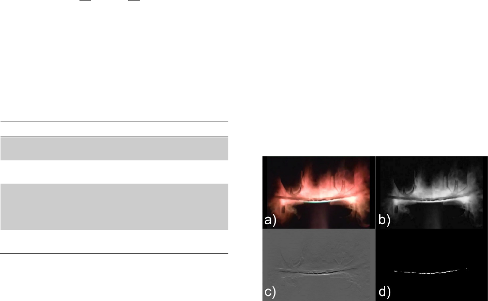
Figure 3. Sample filter progression. a) Original image.
b) Contrast-stretched grayscale image. c) Contrast-
stretched gradient image. d) Binarized image showing
detected test sample edge
Fig. 3 shows the progression of the filtering process.
Once the image is desaturated (Fig. 3b), either a
difference of Gaussians or a directional gradient filter is
applied to find the edges in the image. The filtered
image then is contrast-stretched (Fig. 3c). Finally, a
threshold filter is applied to find the edge of the sample
(Fig. 3d). If necessary, the final binary image can be
CW Mass
Load
Samples
110 g
2 N
Epoxy Resin
Vinyl Ester Resin
326 g
6 N
Epoxy Resin
Vinyl Ester Resin
493 g
9 N
DragonPlate
DragonPlate High-Temp
G10
Cyanate Ester
819 g
15 N
DragonPlate High-Temp
Cyanate Ester
refined by ignoring white areas that are too small or are
outside of some range of expected locations.
The locations of the white pixels in each video frame are
then converted to millimeters of sample deflection using
the conversion ratio calculated from the calibration
image.
3.3 Char Density and Extent
While the rectangular shape of the coupons greatly
simplified the sample installation and extraction, it
created some problems for inferring the char depth from
the mass loss. To circumvent these problems, the actual
char depth of each sample was measured using x-ray
computed tomography. In the resulting scan volumes,
the transmissivity of the charred material was
measurably higher than that of the virgin material, so a
threshold filter could be applied to find the volume of
the whole sample and the volume of the virgin material.
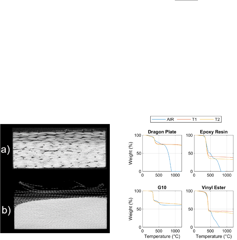
Fig. 4 shows a cross section image of a DragonPlate and
a G10 sample after 38 seconds of exposure. In both, the
line of demarcation between charred material and virgin
material is easily visible, though the difference in the
G10 sample (Fig. 4b) is much more pronounced.
Figure 4. Cross section of DragonPlate sample (a) and
G10 sample (b) x-ray CT scan after 38 seconds of
exposure
By applying a threshold value to the scan volume, a
boundary surface can be calculated for the virgin
material and for the total extent of the sample, from
which the volume of remaining virgin material,
, and
the final volume of the sample,
, can be calculated.
With these values, the initial density
and the final
mass
, the char density and char volume can be
calculated using Eq. 2 and Eq. 3.
=
(2)
=
(3)
The char depth of the sample was calculated using the
average position of the pyrolysis zone within 5 mm of
the center of the sample, the approximate location of the
stagnation point of the plasma flow. The char depth is
reported as the depth relative to the original height of
the sample to eliminate any ambiguity from variation in
the expansion of the char.
4 Results
The relationship between the char rate, thermal
conductivity, and deflection under load of the various
materials was investigated using the measurements
made during the plasma tests. The final analysis of the
post-insertion material strength test samples has not
been performed, so the residual strength of the materials
cannot yet be evaluated.
4.1 Thermogravimetric Analysis
Figure 5. Thermogravimetric analysis results for four of
the materials tested
Thermogravimetric analysis (TGA) and differential
thermal analysis (DTA) were performed on the different
materials used in the test campaign. To perform the
analyses, samples of material between 25 and 50 mg
were exposed to a temperature ramp rate of 10 °C/min
from room temperature to 1200 °C using a
TA Instruments SDT Q600. Both air and nitrogen were
used as purge gases to investigate the difference
between pure thermal degradation and oxidation. The
purge gas flow rate was 100 mL/min.
Fig. 5 shows the TGA results for the materials tested.
All of the materials show a sharp drop in mass at
between 300 °C and 400 °C for both purge gases.
However, only the glass fiber composite, G10, fails to
completely oxidize when air is used as the purge gas.
The other three test materials have completely oxidized
by the time they reach 900 °C.
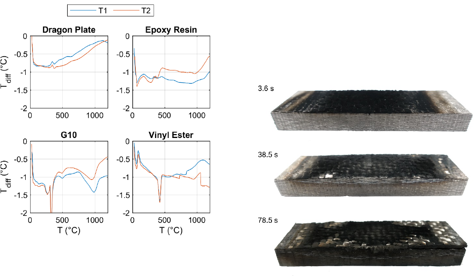
Figure 6. Differential thermal analysis results for four
of the materials tested
Plots of the temperature difference between the sample
and a reference,
, during the test show the
temperatures at which various endothermic and
exothermic processes take place. These data are shown
for the two inert atmosphere tests of each material in
Fig. 6. The spike in temperature difference seen around
400 °C corresponds to the temperature of greatest mass
loss rate and the heat excess or deficit from the pyrolysis
reaction. For the DragonPlate and the hand-layup epoxy
resin samples, this reaction appears to be slightly
exothermic while for the G10 (which has a polyester
matrix) and hand layup vinyl ester-carbon fiber samples,
the reaction is very endothermic. The endothermic spike
around 50 °C to 80 °C for both the epoxy resin and vinyl
ester resin carbon fiber samples likely corresponds to a
drying process as neither of these layups were
autoclaved. In addition, the G10 experiences a further
endothermic process between 600 °C and 1000 °C that
is associated with melting of the glass fibers.
4.2 Char Rate
One of the key properties of any charring material in an
atmospheric entry case is how fast the pyrolysis front
moves through the material, and how much mass is lost
during the charring process. The pyrolysis front speed
will depend on the applied heat flux and the thickness of
the material, so the measured pyrolysis speed is an
indicator of the applied heat flux to the material, all
things being equal.
4.2.1 Visual Observations
Some qualitative data can be drawn from simple
observation of the test samples during and after the tests.
Fig. 7 and Fig. 8 show the visual progression of the
DragonPlate Economy Plate and G10 samples,
respectively, over the duration of the exposure time.
Figure 7. Photographs of DragonPlate Economy Plate
samples after 3.6 s (top), 38.5 s (middle), and 78.5 s
(bottom) of exposure
In the photographs of the DragonPlate samples in Fig. 7,
a layer of soot can be seen on the stagnation surface. It
is unclear if this layer formed during plasma exposure
or after, while the sample was still hot and outgassing.
Regardless, it is highly likely that under reentry-type
aerodynamic shear conditions, this soot layer would be
unable to form.
In the 38.5 s-exposure photograph (middle of Fig. 7)
three distinct colors can be discerned on the edge of the
plate: a char region, a transition region, and a mostly
uncharred region. This is not indicative necessarily of
the depth of the char region throughout the sample, as
the heat flux is higher at the corners of the sample, but
it does show the relative thickness of each region, with
the brown transition region being only a millimeter or so
thick.
Finally, in the longest exposure sample (bottom of
Fig. 7), some delamination of the carbon fiber fabric

layers can be seen. This is an indication that in
circumstances where the entirety of a fabric layer is
exposed to the flow, aerodynamic shear forces may be
able to remove that layer once all of the resin matrix
within the fibers has been charred. However, in
continuous strand weaves as on COPVs where there is
no edge to any given layer, this may not be the case.
Figure 8. Photographs of G10 glass fiber reinforced
polyester resin samples after 7.8 s (top), 38.6 s (middle),
and 78.5 s (bottom) of exposure
The first detail one might notice in the photographs in
Fig. 8 is that several of the fiber layers of the sample
have been completely eroded rather than simply charred.
Indeed, as the resin pyrolyzed and lost structural
integrity, the cloth fibers expanded and peeled away
from the bulk of the material where they were more
easily melted and spalled off, indicating that glass fiber
composites likely are significantly more demisable than
carbon fiber-based materials.
4.2.2 X-ray Computed Tomography Analysis
For 38 out of the 86 char rate test samples used in the
test campaign, X-ray computed tomography (CT) scans
were made of the post-exposure samples and analyzed
(as described in Section 3.3) to calculate the size and
properties of the char layer. Fig. 9 shows the char depth
progression over time for DragonPlate, G10, and
carbon-fiber/cyanate ester resin composites.
In the current study, the oxidizing plasma resulted in a
slower pyrolysis front compared to a non-oxidizing
plasma of a similar cold-wall heat flux. This could be
due to a reduction in hot-wall heat flux due to removal
of oxygen radicals by the reactive gaseous pyrolysis
products expelled through the surface of the material.
In contrast to the pyrolysis front speed, the char density,
shown in Fig. 10, asymptotically approaches a relatively
constant value that is broadly consistent with the char
mass to initial mass ratio seen in the TGA data from
Fig. 5. Also worth noting is that there is not a significant
difference in the char density between the samples
exposed to oxidative flow vs. non-oxidative flow. This
is not a surprising result, as pyrolysis gas expulsion
impedes plasma intrusion into the char layer, and there
is no reason to believe that the degree of final charring
is that sensitive to applied heat flux.
Figure 9. Measured char depth over time for G10,
carbon fiber/cyanate ester resin composite, and
DragonPlate samples
Figure 10. Measured char density over time for G10,
carbon fiber/cyanate ester resin composite, and
DragonPlate samples
Finally, the change in char volume over time, shown in
Fig. 11, illustrates another aspect of the charring and
ablation of different composite materials. The char
volume of the cyanate ester resin composite, for
example, is linear over time as would be expected for a
linear progression of the char through the depth of the
material sample and negligible surface ablation, which

in fact seems to be the case. On the other hand, the rate
of increase in the char volume in the DragonPlate
sample increases over time. This seems to be due to
expansion of the charred material. In contrast, the
G10 sample char volume increase rate initially increases
due to spreading of the fibers released by charring of the
matrix, but then begins to decrease. This is due to
surface ablation by melting and subsequent spallation of
the glass fibers.
Figure 11. Measured char volume over time for G10,
carbon fiber/cyanate ester resin composite, and
DragonPlate samples
4.3 Material Strength
Because the ICP facility used for the current study is a
subsonic facility, it is not possible to study the effects of
aerodynamic shear on the ablation rate of the material,
though some spallation was observed in the glass fiber
reinforced samples as droplets of molten glass were
blown from the material surface. Instead, to get an idea
of how the overall integrity of the material changes with
heat absorption, some thin material coupons (< 3 mm
thick) were exposed to the plasma under a constant
bending load and the surface deflection of the coupon
was observed throughout the test using a digital video
camera. An example of the type of deflection data
obtained is shown in Fig. 12. Digital processing of the
video of the sample provides the position of the sample
surface within an error of ±0.15 mm at a rate of
~24 frames per second, though in some frames, the
brightness of the plasma can interfere with detection of
the sample surface.
Unfortunately, the geometry of the sample holder
required by the counterweight mechanism and the
necessity of keeping the clamp arms out of the plasma
places the stagnation point side of the coupon under
tensile load. This is the stronger orientation for the
sample under the bending load, so failure is observed at
a much higher char percentage than would be the case
were the force direction to be flipped.
Figure 12. Example sample deflection data for a wet
layup epoxy resin material sample under a 2 N load. The
plasma plume is located at x=0 and is flowing in the
+y direction.
Regardless, an estimate of average elasticity,
, of the
sample at any point in the test can be calculated from the
deflection of the sample by fitting Eq. 4 (where is the
vertical displacement, is the distance between the
inner load points, is the moment of area, and is the
load at each point) to the measured deflection as a
function of x, assuming the sample is uniform and
isotropic. This is not the most accurate, but the
calculated elasticity is still a good qualitative indication
of the degradation of structural properties.
(
)
=
2
1
2
(4)
Additionally, the amount of heat absorbed by the sample
coupon can be estimated using the control volume
analysis depicted in Fig. 13. For simplicity, the heat loss
through the edges of the sample is assumed to be
negligible due to the relatively small edge surface area.
The hot wall heat flux,
, is calculated from the
surface temperature of the sample measured by the
pyrometer during the test and the cold wall heat flux
measured before the test. The back side-radiative heat
loss,
, and stagnation side-radiative heat loss,
, are
calculated using a gray body assumption and the
measured back side and stagnation side temperatures,
respectively. The heat absorbed by the sample,
, is
calculated from these heat flux values using Eq. 5.
(
)
=
(
)
(
)
(
)
(5)
Plotting this average elasticity against the total absorbed
heat of the sample, as in Fig. 14 to Fig. 16, provides
some insights into how the material degrades over time
in a re-entry environment.

Figure 13. Control volume analysis of test sample
On a log-linear plot, the slope of the degradation line is
bi-linear. This is most apparent in the DragonPlate
samples in Fig. 16 but can be seen in the wet layup
epoxy samples in Fig. 14, and to a lesser extent in the
vinyl ester samples in Fig. 15.
Figure 14. Calculated average elasticity of the wet
layup carbon fiber/epoxy resin material as a function of
absorbed heat for each test condition
The spread in average elasticity values between tests is
also seen to be much larger for the wet layup samples
than for the DragonPlate samples. This is likely because
the DragonPlate samples are a commercial off-the-shelf
product, and the wet layup samples were laid up by hand
in a NASA JSC machine shop and may have been
subject to more variability in matrix infusion and
between specimens.
Some individual tests show a dip in elasticity before
recovering, especially at lower values of absorbed heat.
This is an artifact of the image processing algorithm
being unable to find the true surface of the sample due
to interference from the incandescence of the charring
and ablation products in the plasma.
Figure 15. Calculated average elasticity of the wet
layup carbon fiber/vinyl ester material as a function of
absorbed heat for each test condition
Also indicated in Fig. 14 to Fig. 16 are heat absorption
limits for each test and the breakpoint
at which the
rate of structural degradation increases. The heat
absorption limit, where the sample experienced
complete structural failure, is indicated by the sharp
downturn at the end of each plot before the data is cut
off by the loss of the sample. Comparisons of these
values for the various materials and test conditions are
given in Fig. 17 and Fig. 18, respectively.
Figure 16. Calculated average elasticity of the
DragonPlate carbon fiber/epoxy material as a function
of absorbed heat for each test condition
Variability in the degradation breakpoint, shown in
Fig. 17, is extremely low for the DragonPlate Economy

Plate samples, but varies by as much as 150 °C for the
vinyl ester -and wet layup-epoxy matrix samples. This
could be significant, but is likely due to more variability
in the hand-made samples.
More surprising is the difference in failure point
between the DragonPlate and the wet layup epoxy
samples. In some of the tests, the wet layup samples
were able to absorb almost twice as much specific heat
as the DragonPlate samples before ultimate failure.
Figure 17. Degradation breakpoint heat absorption for
each material and test condition
Figure 18. Heat absorption structural failure point for
each material and test condition
4.3.1 Cyanate Ester and Phenolic
Even under the highest load tested, the DragonPlate
High Temp samples did not deflect at all during an 80 s
test under any conditions. Given the results from the
char analysis, this is more than enough time for the
entire sample to have charred through, indicating that a
significant amount of the matrix material remains as
char material with enough integrity to hold the fibers
together.
The cyanate ester materials, on the other hand,
eventually exhibited structural degradation under the
test conditions, though the failure did not manifest as a
reduced elasticity. Rather, the cyanate ester samples
remained straight along most of the length and creased
at one or both of the inner load points at some time after
50 seconds of exposure.
5 Modeling
Based on these test results, the authors have developed
a charring and ablation model for G10, carbon fiber-
epoxy, and carbon fiber-polyester composites. The
model is based on that proposed by Hidalgo, et al. [6]
and uses TGA data for the specific materials used in the
char testing to calculate a remaining mass as a function
of temperature. The temperature of the sample is
calculated using a finite difference thermal transport
model assuming an inert material, and then the updated
temperature is used to calculate an updated char
fraction.
5.1 Assumptions
Several simplifying assumptions were made to
implement the model more easily.
• Expansion in char material is negligible
• Interior charring is a completely anoxic process
• The mass loss in a mesh cell is equal to the
mass loss in a TGA sample of the material at
the mesh cell temperature
• The thermal conductivity and thermal capacity
of the char material is equal to that of bare
woven fibers in air.
5.2 Mass Loss Model
The TGA data shown in Section 4.1 were compiled in
MATLAB and functions were fit piecewise to the curves
for fast evaluation. The assumption of anoxic charring
allows for the exclusion of the air-purged TGA data sets;
only the nitrogen-purged TGA will be used to calculate
the char mass loss. In addition, complete data sets only
exist for the DragonPlate and G10 materials, so these are
the only two materials that will be discussed.
The mass loss of the DragonPlate material with
increasing temperature can be seen in Fig. 19 (run T2 is
chosen as the exemplar), along with a 4-region
piecewise fit. The fit functions for each region are
defined as in Eq. 6 through Eq. 9.
(
)
= 1 ,
(
< 100°
)
(6)
(
)
= 1.0235 2.346 × 10
,
(100° < 343°)
(7)
(
)
= 4.9943 0.0195 + 2.2413 × 10
,
(343°< 435°)
(8)
0
100
200
300
400
500
2% air,
low q
2% air,
high q
0% air,
low q
0% air,
high q
Q
break
(J/g)
DragonPlate Epoxy Vinyl
0
200
400
600
800
1000
2% air,
low q
2% air,
high q
0% air,
low q
0% air,
high q
Q
max
(J/g)
DragonPlate Epoxy Vinyl

(
)
= 0.7724 4.4837 10
,
(
435° < 1200°
)
(9)
Figure 19. Remaining mass fraction of DragonPlate
composite with increasing temperature (T2 run),
including fit functions
Similarly, the mass loss of the G10 material with
increasing temperature can be seen in Fig. 20 (run T1
chosen as the exemplar); the fit functions for each region
are defined as in Eq. 10 through Eq. 14.
Figure 20. Remaining mass fraction of G10 composite
with increasing temperature (T1 run), including fit
functions.
(
)
= 1,
(
< 230°
)
(10)
(
)
= 1.0767 3.333 10
,
(
230° < 305°
)
(11)
(
)
= 2.8813 0.00625 , (305°
< 345°)
(12)
(
)
= 0.817 2.667 10
, (345°
< 525°)
(13)
(
)
= 0.7143 7.111 10
, (525°
< 1200°)
(14)
5.3 Finite Difference Model
Now that a model for mass loss with temperature has
been developed, it must be combined with a thermal
transport model to calculate the char depth as a function
of time. A new time-accurate finite difference code was
developed to simulate the char depth test using material
properties from the ORSAT material database and the
recently-developed TGA mass fraction models. The
algorithm implemented to solve this problem is outlined
as follows:
• Compute the heat transfer into the front face
(including the plasma jet and radiation)
• Compute the thermal conduction between all
nodes
• Compute the thermal radiation from the back
face
• Compute new nodal temperatures from net heat
transfer per node
• Update the temperature-varying material
properties
• Iterate on the nodal temperatures and heat
fluxes during a time step until they converge
• Update the mass fraction for each node, then
continue to the next time step and perform the
process again
Some potential sources of uncertainty in this model
include: the areas of the front face which do not receive
heating from the plasma torch, but do have heat
conducted and radiated away; variation in thermal
properties away from the ORSAT database materials;
and pyrolysis shielding from the plasma torch or
removing heat through outgassing.
5.4 Model Results
The finite difference model simulations were run for the
G10 and DragonPlate materials, emulating the char
depth tests. Four fiducial points were used for each
material to assess the progression of the char during a
test.

The G10 model, with constant thermal properties, was
quick to run, completing in approximately 12 hours (vs.
78.5 seconds of simulated time). The char depth for G10
is determined as the location where the mass fraction
decreases to 70% of the pristine material, based on the
final mass of the TGA test in Fig. 20. The temperature
distribution and char depth progression through the
simulated sample can be seen in Fig. 21. The simulated
and actual char depth results are compared in Tab. 3.
Table 3. Comparison of simulated char depth with
sample test results for G10
Time
(sec)
D
char
(mm)
Simulated
D
char
(mm)
δ
(mm)
δ
(%)
3.6
0.48
0.41
-0.07
-15%
8.5
0.80
1.0
0.2
25%
38.5
2.7
3.1
0.4
15%
78.5
5.4
5.1
-0.3
-6%
Figure 21. Temperature and mass fraction profiles of
the simulated GFRP material at the fiducial time points
in the G10 test samples
The DragonPlate model, with its temperature-varying
thermal properties, required approximately 40 hours to
run (with 78.6 seconds of simulated time), significantly
longer than the G10 model. The char depth for
DragonPlate is determined as the location where the
mass fraction decreases to 75% of the pristine material,
based on the final mass of the TGA test in Fig. 19. This
simulation delivered comparable results, with the plots
of temperature distribution and char depth progression
through the simulated sample seen in Fig. 22. The
simulated and actual char depth results are compared in
Tab. 4.
Figure 22. Temperature and mass fraction profiles of
the simulated CFRP material at the fiducial time points
in the DragonPlate test samples
Table 4. Comparison of simulated CFRP char depth
with measured char depth in DragonPlate sample
Time
(sec)
D
char
(mm)
Simulated
D
char
(mm)
δ
(mm)
δ
(%)
3.6
0.61
0.2
-0.41
-70%
8.5
0.92
1.0
0.08
7%
38.6
3.1
3.4
0.3
10%
78.6
6.2
5.9
-0.3
-5%
Finally, a fine-grained comparison of the simulated char
progression and the test data can be seen for G10 and
DragonPlate in Fig. 23 and Fig. 24, respectively. Both
simulations agree well with the test data, though the
simulated pyrolysis front pulls ahead of the measured
data around the 40-second point before slowing down
and matching the test data again by the 80-second mark.
The likeliest source of this discrepancy is the 3D nature
of the charring process in the plasma torch tests.
As another check of the model’s accuracy, the measured
and simulated front- and back-surface temperature
profiles can be compared. These profiles are shown in
Fig. 25 and Fig. 26 for G10 and DragonPlate,
respectively. It is relatively clear from both of these
figures that the thermal conductivity used to simulate
both the G10 and the DragonPlate is a little too high, as
the simulated back side temperature overshoots the
measured temperature by 20–50 K. A lower
conductivity would also cause the front side temperature
to better match the measurements, as a lower conduction
rate into the material would cause the simulated front
side temperature to rise much more rapidly and plateau
at a slightly higher temperature.

Figure 23. G10 simulated temperature and mass
fraction distribution vs. time, compared to the measured
char depth in the test samples
Figure 24. DragonPlate simulated temperature and
mass fraction distribution vs. time, compared to the
measured char depth in the test samples
Figure 25. Comparison of simulated temperature in
GFRP to the measured front (top axes) and back
(bottom axes) surface temperatures from four different
tests using G10
Figure 26. Comparison of simulated temperature in
CFRP to the measured front (top axes) and back (bottom
axes) surface temperatures from four different tests
using DragonPlate
For the GFRP material in Fig. 25, especially, some of
the mismatch in the front side temperature is due to
uncertainty in the appropriate surface emissivity to
apply to the pyrometer measurement. A surface
emissivity of 0.86 is assumed, but as the surface chars,
this value will very likely increase to 0.9 or 0.92,
causing a significant error in the reported front surface
temperature value.
6 Conclusion
The NASA ODPO conducted an extensive test series to
improve understanding of the behavior of glass- and
carbon fiber-reinforced polymers in a realistic reentry
thermal environment.
Novel techniques such as X-ray CT scans and in-situ 4-
point bending load application to the test samples were
used to measure the charring rate and strength
degradation of several different fiber-reinforced
polymers. Future work includes cross-sectioning
selected samples to compare to X-ray CT scans and
measuring the post-exposure strength of selected test
coupons in a laboratory 4-point bend configuration to
compare to the in-situ results presented here.
A new thermal charring model ready for implementation
into ORSAT was developed using thermogravimetric
analysis data and validated against char depth rate tests
in the University of Texas at Austin plasma torch
facility. The thermal charring model was found to agree
well with the available test data in terms of both char
depth and front- and back-side temperature profiles for
both materials examined. Future improvements to the
model include using more accurate char material
thermal conductivity and thermal capacity values from
the literature and including the effect of the heat of
pyrolysis on the effective thermal capacity.
The new charring model, together with further
enhancements of the surface ablation and spalling
models that can be made using this test data, will
improve the ability of the ODPO to accurately predict
the ground casualty risk for atmospheric disposal of
modern spacecraft with a large number of composite
structures.
7 References
1.
Greene, B.R., & Sanchez, C.M. (2019).
Demisability of GFRP and CFRP Components of
Reentering Orbital Debris: Phase I Test Results. In
10th International Association for the
Advancement of Space Safety Conference
, El
Segundo, CA.
2.
Lips, T., Fritsche, B., Kanzler, R., Schleutker, T.,
Gülhan, A., Bonvoisin, B., Soares, T., & Sinnema,
G. (2016). About the Demisability of Propellan
Tanks During Atmospheric Re-
Entry from LEO. In
8th International Association for the Advancement
of Space Safety Conference, Melbourne, FL.
3.
Griffis, C.A., Masumura, R.A., & Chang,
C.I..(1981). Thermal Response of Graphite Epoxy
Composite Subjected to Rapid Heating. US Naval
Research Laboratory, Washington, D. C..
4.
Blasi, C.D. (2000). The State of the Art of
Transport Models for Charring Solid Degradation.
Polymer International. 49(10), pp1133-1146.
5.
Gibson, A.G., Feih, S., & Mouritz, A. (2011).
Developments in Characterising the Structural
Behaviour of Composites in Fire. In
Composite
Materials: A Vision for the Future
, (Eds. L.
Nicolais, E. Milella & M. Meo) London, U.K.,
Springer, pp187-217.
6.
Hidalgo, J.P., Pironi, P., Hadden, R.M., & Welch,
S. (2015). A Framework for Evaluating the
Thermal Behavior of Carbon Fibre Composite
Materials. In Proc
eedings of the 2nd IAFSS
European Symposium of Fire Safety Science
,
Nicosia, Cyprus.
7.
McKinnon, M.B., Ding, Y., Stoliarov, S.I.,
Crowley, S., & Lyon, R.E. (2017). Pyrolysis Model
for a Carbon Fiber/Epoxy Structural Aerospace
Composite. Journal of Fire Sciences. 35(1), pp36
-
61.
8.
Quang Dao, D., Luche, J., Richard, F., Rogaume,
T., Bourhy-
Weber, C., & Ruban, S. (2013).
Determination of Characteristic Parameters for the
Thermal Decomposition of Epoxy Resin/Carbon
Fiber Composites in Cone Calorimeter.
International Journal of Hydrogen Energy. 38(19),
pp8167-8178.
9.
Kucner, L. (1992). Experimental Investigation of
Fire Damage to Composite Materials.,
Boston,
MA: Massachusettes Institute of Technology,
Department of Aeronautics and Astronautics,
10.
Biasi, V., Leplat, G., Feyel, F., & Beauchêne, P.
(2014). Heat and Mass Transfers Within
Decomposing Carbon Fibers/Epoxy Resin
Composite Materials. In 11
th AIAA/ASME Joint
Thermophysics and Heat Transfer Conference
,
Atlanta, GA.
11.
Di Modica, P. (2016). Modelling Fire Behaviour of
Composite Materials. School of Mechanical and
Systems Engineering, Newcastle University.
12.
Hill, D.J., & Torero, J.L. (2004). Experimental
Characterization of the Effect of Charring on the
Residual Load Carrying Capacity of a Structural
Fibre Reinforced Composite. In 10th Interflam
,
Edinburgh, UK.
13.
Kandare, E., Kandola, B.K., Myler, P., & Edwards,
G. (2010). Thermo-
Mechanical Responses of
Fibre-
Reinforced Epoxy Composites Exposed to
High Temperature Environments. Part I:
Experimental Data Acquisition.
Journal of
Composite Materials. 44(26), pp3093-3114.
14.
Bai, Y., Post, N.L., Lesko, J.J., & Keller, T. (2008).
Experimental investigations on temperature
-
dependent thermo-
physical and mechanical
properties of pultruded GFRP composites.
Thermochimica Acta. 469(1-2), pp28-35.
15.
Burns, L.A., Feih, S., & Mouritz, A. (2009). Fire-
Under-
Load Testing of Carbon Epoxy Composites.
In 47th Aerospace Sciences Meeting, Orlando, FL.
16.
Greene, B.R., Clemens, N.T., Varghese, P.L.,
Bouslog, S., & Del Papa, S.V. (2017).
Characterization of a 50 kW Inductively Co
upled
Plasma Torch for Testing of Ablative Thermal
Protection Materials. In AIAA SciTech Forum -
55th AIAA Aerospace Sciences Meeting
,
Grapevine, TX.
