NISTIR
89-4030
Ignition
and Lateral
Flame
Spread
Characteristics of
Certain
Composite
Materials
T. Ohlemiller
S. Dolan
U.S.
DEPARTMENT
OF
COMMERCE
National Institute of Standards and Technology
(Formerly
National Bureau of Standards)
National Engineering
Laboratory
Center for Fire Research
Gaithersburg, MD 20899
January 1989
Sponsored
by:
David Taylor Research Center
United
States
Navy
Annapolis, MD


NISTIR
89-4030
Ignition
and Lateral
Flame
Spread
Characteristics
of
Certain
Composite
Materials
T. Ohlemiller
S«
Dolan
U.S.
DEPARTMENT
OF COMMERCE
National
Institute of Standards and Technology
(Formerly National
Bureau of Standards)
National Engineering
Laboratory
Center
for Fire
Research
Gaithersburg, MD 20899
January 1989
National
Bureau of Standards became the
National Institute of Standards and
Technology
on August
23,
1988,
when
the Omnibus
Trade and
Competitiveness Act was signed.
NIST retains
all NBS functions. Its
new
programs
will encourage
improved
use
of technology
by U.S.
industry.
Sponsored
by:
David Taylor Research Center
United
States
Navy
Annapolis, MD
U.S.
DEPARTMENT OF COMMERCE
C.
William Verity, Secretary
Ernest Ambler, Acting Undersecretary
for Technology
NATIONAL INSTITUTE
OF STANDARDS
AND TECHNOLOGY
Raymond
G.
Kammer, Acting Director


TABLE OF CONTENTS
Pa
g
e
List
of Tables
iv
List
of Figures .............................
v
Abstract ............................ 1
1.
Introduction ....................... 1
2.
Experimental
............................
2
Materials .............................
2
Measurement
Techniques
................
3
3.
Results and
Discussion
.......................
4
3.1.
Ignitability
...................
4
Sample
Behavior
................
4
Heat Flux
Dependence of Ignition Delay 5
Correlation of Ignition Data ...........
6
3.2.
Lateral
Flame
Spread
................
8
Sample Behavior
..........
.
8
Lateral Flame Spread Parameters.
........
9
4. Summary
and Conclusions 11
5. References
.......................
13
iii

LIST OF TABLES
Page
Table 1.
Parameters Inferred from
LIFT Ignition
Data
14
Table
2.
Parameters Inferred from LIFT Flame
Spread Data
14
IV
LIST
OF
FIGURES
Page
Figure 1.
Ignition delay
time vs. incident
heat
flux
for CG Camel honeycomb
panel. Equation
shown is least-squares
fit and
R is the
correlation coefficient.
............
15
Figure
2.
Ignition
delay
vs.
incident heat
flux for CG
Camel and CG Yellow
honeycomb panels
............. 15
Figure 3. Ignition
delay
time vs.
incident heat
flux
for CG Yellow honeycomb
panel; face and
edge ignition data points
are distinguished
......... 16
Figure 4. Ignition delay time vs.
incident heat flux
for CG Green Vinyl
honeycomb panel.
Equation
shown
is least- squares fit
and R is the
correlation coefficient
................... 16
Figure 5. Ignition delay time vs.
incident heat flux
for OC Armor composite armor
panel. Face and
edge data points
are distinguished. Equations
shown
are leas t- squares fits
and R
values
are
correlation
coefficients
. ........
17
Figure 6. Ignition model
correlation for CG
Camel and
CG Yellow
treated as a single
material. Data
points
for face ignition only.
........ 18
Figure
7. Ignition
model correlation
for CG Green
Vinyl.
Data points
for face ignition only
18
Figure
8. Ignition model
correlation for face ignition
of
OC Armor
............
19
Figure
9. Ignition
model correlation
for
edge ignition of
OC Armor
................. 19
Figure
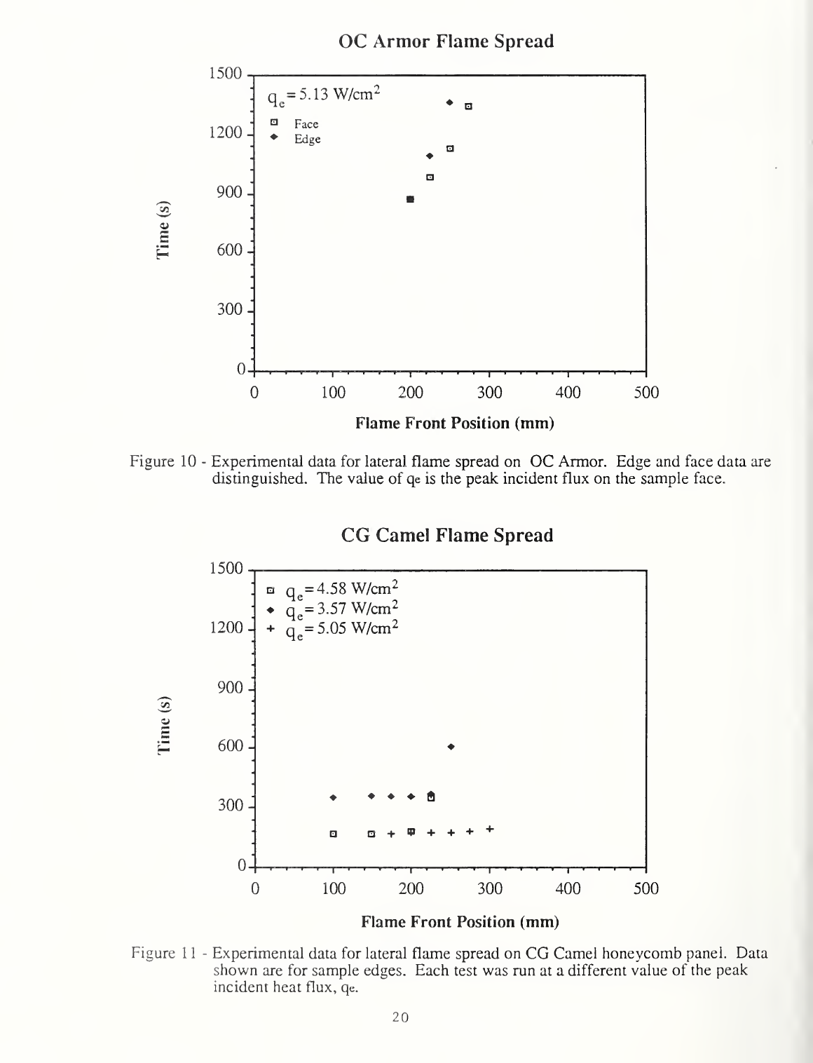
10. Experimental data
for lateral flame
spread
on
OC Armor.
Edge and
face
data are distinguished.
The value
of
q
e
is the peak incident flux on
the sample
face
...........
20
Figure
11.
Experimental
data
for lateral flame spread on
CG Camel honeycomb panel.
Data
shown
are for
sample edges.
Each test
was
run at a
different
value
of the peak incident heat flux,
q
e
20
v

Figure
12.
Experimental data for lateral
flame
spread
on
CG Camel honeycomb panel. Data are for sample
face. Results for two different values of the
peak incident heat flux are shown
Figure 13. Model
correlation
of
lateral
flame
spread on
CG
Green Vinyl honeycomb panel. Line
shown
has
been
forced to
pass
through
a
value
of
0.87 W/cm
2
on the horizontal axis
21
21
Figure 14.
Distribution of
heat flux
incident on
sample
surface,
normalized
by
peak value
22
vi

Ignition and
Lateral Flame Spread Characteristics
of Certain
Composite Materials
Abstract
The LIFT
apparatus
was used to obtain information on the ignition
and lateral
flame
spread
characteristics of
two types of composite materials. The
first
type
was
a
honeycomb
sandwich panel; three different facings
were tested
with
this
material.
The
second type of material
was
a composite armor.
There
was
a
substantial
variation in
the ignitability of the
various material
combinations
with
a
vinyl
-faced honeycomb panel being the
most ignitable
and
the
composite
armor being the
least ignitable.
The ignition
behavior of the
facings of all
materials was correlated by
a simple
predictive model. Only
the vinyl-
faced honeycomb
panel showed significant
normal flame
spread under
the conditions
examined
though some flame
"advancement"
was
seen
with the
others. All
of the
materials exhibited
worse flammability
properties at their
edges
as compared
to their facings.
1)
Introduction
This report
summarizes the results
of ignitability and
lateral flame
spread
tests
performed on
two
substantially
different types
of composite
materials,
Nomex
sandwich panels and a
composite ballistic armor.
The tests
were
performed using the Lateral
Ignition and Flame
Spread (LIFT) apparatus
at the
NIST Center for Fire Research. The
objective is to begin
to establish
a
database
on
the flammability of materials of
potential
interest to the
Navy
for shipboard
applications such as the
Composite Deckhouse.
The general approach
to
flammability assessment
followed here is discussed in
detail
in Reference
1.
Briefly, the
approach consists
of determining
sets of
effective parameter values which can be
utilized in the
context of
simplified
models of
ignition or flame
spread to predict this
behavior
in
a
variety
of
different
contexts. Examples of such
parameters
are the
minimum surface
temperature
for ignition and the
minimum incident
heat flux
on a material
surface necessary
to support
continued flame
spread.
The
principal measure of
ignitability is
the delay time
between
the
onset of a
constant
heat flux to the surface of
a material
and the first
appearance
of
a
flammable
mixture of gases issuing
from the
surface of the
material.
The
presence of a flammable gas mixture
is sensed by
placing a
small pilot
flame
in the gas
stream issuing from
the surface
(positioned so
that it
does not add
to the
external heat flux on the
sample surface)
.
The delay
time is dependent
on the
incident
flux
level; a
complete
ignitability
characterization thus uses
a range
of heat fluxes from 7 or 8
W/cm
2
down
to
the minimum flux
necessary
for
ignition. This minimum is
dependent
on
the
physical and chemical
characteristics
of
the
material as
well
as the
conditions of
heat exposure.
These
measured data are fitted to a simple
model of the
ignition process to
1

infer the
values of two parameters in the model:
the effective
thermal inertia
of the
sample (product of thermal conductivity, density
and heat
capacity) and
the minimum
surface temperature
for ignition. The model equation
can then
be
used to
predict the ignition delay for the sample
material
in
other
conditions
such
as
for
larger scale vertical surfaces.
Flame
spread
rates on
vertical
flat
surfaces
are approximately equal
in both
the lateral
and downward directions; spread rates
on horizontal flat
surfaces
are
also comparable
[2,
3].
Thus only one of these
configurations (all of
which involve opposed flow flame spread; see Ref.
1)
needs to be measured
to
obtain
the expected behavior
for all
three.
The LIFT apparatus measures
lateral spread on a vertical surface
.
This rate is dependent on
the
temperature of the surface ahead of the spreading flame. This temperature
could be
increased
in
a fire by an external heat flux (from some other burning
object, for
example) incident for a
varying
amount of time. Generally such an
external flux can increase the sample surface temperature only up to an
equilibrium
value
dependent on that flux
level and
on the rate of heat loss
from the surface. The LIFT apparatus takes this preheating effect into
account
by
first allowing the sample surface to equilibrate locally
with
an
external flux. This local flux
varies
monotonically along the
surface of
the
sample so that one can obtain a measure of the heat flux
dependence of
the
lateral flame spread velocity. Furthermore, one can obtain the minimum flux
at which sustained lateral spread is possible. By fitting these data to a
simplified model of opposed
flow
flame spread, one can obtain
another
effective parameter for the material, a measure of the flame heat transfer to
the sample surface
during flame spread. The
fitted model
can then be
used to
predict the opposed flow flame spread rate of the material in any of the
configurations
mentioned
above
for larger-sized samples.
These are the procedures applied to the
materials of
interest
here.
They
met
with
varying degrees
of success due to peculiarities of sample
behavior,
as
discussed below.
2)
Experimental
Materials
:
All
samples
were
obtained from the U. S.
Navy David
Taylor
Research Center;
they are the
first in a series
of composite materials to be
subjected
to an extensive flammability
characterization in
aid of their
evaluation for
shipboard use. The first
type of
composite was a Nomex
honeycomb sandwich
panel
1
.
Three different panels were tested
having
different finishes on
the heated surface. Two of the finishes
appeared
to be
substantially similar,
differing only
in
color. One
was described as "camel"
In color; the
other
was yellow.
For both of these the color
layer had the
appearance
of a
low
gloss paint intimately bonded to the layers
below.
The
third surface
finish on the honeycomb panels was apparently a
textured vinyl
sheet, light green-yellow
in color, that appeared to be
glued to the outermost
1
Product
names are
provided
here only for purposes of
clarity; they do
not
imply any
endorsement by NIST.
2
layer
of
the sandwich panel; this vinyl layer
was
readily
strippable from the
sandwich
panel. All of
these
panels
were
nominally 15 h mm
(5/8
in.)
thick
and the
honeycomb
core accounted for approximately
8 mm
(1/2
in.) of this
thickness.
The
sandwich faces were
multilayer in character including
one
or
more
plies of
woven glass fibers. In the results that follow, these
panels
are
designated as GG
Camel, CG Yellow and CG Green Vinyl.
The
second
type of
material was
a
composite armor based
on S-2
glass
and a
phenolic
resin;
this was a ballistic armor designed for stopping the
penetration
of small,
high speed metal fragments. The glass is in the form of
a large
number of
woven roving
plies
with
the
resin
dispersed throughout.
The
high glass
content
(80
%
by
weight)
necessitated that this material be cut to
size
for the tests by
means of a diamond
saw.
The nominal thickness
was
12 h
mm
(1/2
in.). In
the results
below
this material is designated
as OC Armor.
Measurement
Techniques: The LIFT apparatus was used for both the ignitability
and
lateral flame
spread measurements. For the ignition tests the sample
was
156 mm
(6
1/8
in.) square
and it was placed in the end of the LIFT sample
holder
which
provides
a
nearly uniform heat flux from a gas -fired
panel. The
procedures
followed with regard to calibration
and
test
measurements
were
those currently
under consideration by ASTM
[4].
Briefly,
a dummy specimen,
fabricated to support a
heat flux gage, is mounted in the
apparatus. The
radiant
panel and the pilot flame
(acetylene
/
air)
,
positioned
above
the
top
edge
of the sample, are
stabilized and the
flux
to the specimen
surface is
recorded. The dummy
specimen holder is quickly
removed and the actual
specimen holder rapidly inserted. At full insertion a
stopwatch is started.
The
test ends when a flame is attached
somewhere
on the
sample and the
requisite time for this is noted from
the
stopwatch.
Flame
attachment means
that a gas phase flame has its base on the sample so
that its own heat flux
assures a continuing flow of fuel gases from the
sample to feed the flame. It
is not necessary that the foot of the flame
cover
a
large portion of the
sample
face or the sample edge to satisfy this
criterion and, in fact, it
frequently did not.
Prior to
flame attachment, flashes of
flame were often
seen; these would
propagate rapidly from the
pilot flame to some region of the
sample surface
and then disappear. Such a
phenomenon does not represent true
ignition.
These procedures were repeated
with new samples at
several
heat
flux levels
to establish the variation of ignition
delay time
with
heat flux.
Establishment of the
minimum heat flux
for ignition generally
requires
several
tests
in
which
one attempts to bracket the limit.
The longest delay time one
waits
for ignition
has been arbitrarily set
at 22 minutes. It is
apparent
from the
resulting data that this is adequate.
The lateral
flame spread tests were run in
the same apparatus but
with longer
samples
(794
mm or 31
k
in.). As
noted
above, the sample
temperature affects
the flame
spread rate.
The normal
procedure
calls for pre-heating
the sample
until
it
reaches equilibrium with the
local incident flux
(recall this
varies
along
the length
of the sample)
.
This
procedure
was followed except in the
case
of the
CG Green Vinyl material.
Waiting for full thermal
equilibrium
here
allowed
the
vinyl
surface coating to
fully degrade
to the point
where
it
was
not
ignitable by the usual ignition method.
The length of time
required
for
thermal
equilibrium
with
the incident heat
flux is determined
from the
3

ignitability
results by correlating them
in a
manner which is
illustrated
below.
After
pre -heating (typically with the maximum flux just above
the
minimum for
ignition) the gases
issuing
from
the
surface are
ignited with
a
pilot
flame
and flame
spread on the pre-heated surface
is initiated. Progress
of the flame front
across the sample face (toward the direction
of lower
incident heat flux) is
followed visually with
an
optical
arrangement which
allows determination of the times at
which
the flame reaches
pre - determined
positions (typically 25 mm apart). The flame front is not necessarily
flat;
one normally
focuses
on the progress
of the flame
across the mid-height of
the
sample. The actual flux incident at each position is precisely calibrated
beforehand. Thus
when
the flame reaches a position on the sample face beyond
which
it
will
not propagate, one
knows the corresponding minimum heat
flux for
lateral flame
spread (and
the
corresponding minimum sample surface temperature
for
continued spread)
.
This same procedure is repeated
for
three separate
samples of each material.
3)
Results and
Discussion
3.1)
Ignitability
Sample Behavior.
All of the samples
exhibited some form of idiosyncratic
behavior
when
heated. CG Camel and CG
Yellow behaved alike. Both underwent
an
explosive delamination of the outermost layers relatively early in the
heating process. This appeared to be due to the
volatility of some component
binding these layers together;
when
it began to vaporize, the
vapors
could not
escape
through the non-porous "paint" layer.
Bubbles formed between
layers,
expanded and then blew loose all
layers
down to the outermost glass ply.
Sometimes these bubbles
turned
the
sample
face into
an
irregular surface with
several "flaps" of loosened material opening out randomly; other times most of
the sample surface was occupied
by one
large "flap"
of
disrupted material.
In
all cases
these flaps undoubtedly sharply altered the
flow
of heat into the
sample
interior. Soon after the explosive delamination the
various
protruding
fragments
of the outer layers charred rapidly with a considerable efflux of
white smoke.
Only at high incident fluxes did this smoke
ignite and
only then
did the
actual face of the sample ignite. When a sample
was
exposed to
lower
fluxes this smoke emission ended
and many
minutes passed before
visually
smaller amounts of smoke began to be emitted once again. In the
interim the
glass
plies detached from the Nomex core, also as a result
of internal
pressure,
but they remained intact, merely bulging
outward about
1/2
cm in the
sample center;
this too must
have
affected the
heat flow in the sample. This
internal
pressure
was
evidently relieved out through the
edge of the sample;
this appeared to establish a pathway to the outside used
preferentially by all
subsequent
gases generated in the sample interior.
As a
consequence, the
ignition and subsequent burning of the sample at
these
lower
fluxes
was
at one
or
more
edges
exclusively.
The CG Green Vinyl samples might potentially have
behaved in a similar manner
since it appears to have a structure similar to the
other CG materials.
However,
the surface layer of (presumed) vinyl material
was so much more
flammable
than the surface layers
of
the
other two CG materials
that it
dominated
the
observed behavior.
This layer
rapidly softened
and bubbled,
4

even at
very low fluxes. The bubbles
swelled considerably,
sagged and
charred
with
emission of visible smoke. The
bubbles, some
of
which were several
centimeters in
diameter,
undoubtedly have
a
substantial
effect on the
heat
transfer
in the
sample. The evolved smoke was readily ignited
by
the pilot
flame
with
subsequent flaming
over
most of the sample face. The burning
of
this vinyl
facing
lasted long enough (up to
two
minutes) for it to be
considered the
primary hazard. The
subsequent ignition
and burning of
the
deeper layers
of the
composite, analogous
to
the
behavior
noted for the
other
two
CG
materials,
was noted in a
few tests but
was
not followed in detail.
The OC Armor,
with its drastically different
structure, behaved quite
differently
from the
above materials in some
respects.
The geometry
of the
material
never
changed at any time in an
ignition test. The surface
simply
turned
black
slowly with
very
little
visible smoke emission. The high
mass
per unit
of facial
area of the material
slowed the heat-up and subsequent
ignition
process.
Flaming ignition,
when
it finally
occurred, was either at
the sample edge or at
the sample face.
Face ignition
was always localized to
one
or a few
very small (few mm) jets of gas
which appeared to issue from
pinpoint
defects in the
sample face. Typically,
as time increased, the size
of each flame
increased
somewhat, as did the number of jet- like
flames.
However, the full facial area of the
sample was never
involved
in
flaming.
Edge
ignition was more
diffuse; it presumably resulted from
defects
which
happened to be near
the cut edges of
the sample. Unlike the
situation
with
the CG
samples, here edge
ignition or face ignition could
occur over the same
flux range (see
below)
.
Heat Flux Dependence of Ignition
Delay, Figure 1 shows the
ignition delay
time for CG Camel as a
function
of the
incident radiant heat
flux. The line
through
the
data points is a best fit polynomial,
not an ignition
model line;
the model fit is discussed
below.
Clearly,
the incident flux has
a drastic
effect on
the ignition delay time
especially as one gets
near the minimum
flux
for ignition (here about
2.2
W/cm
2
).
What
is
not apparent from the
smooth line
in
the
Figure is that there is a transition
in the range
from about 3
.
0 to
4.0 W/cm
2
from edge
ignition (at
lower fluxes) to
face ignition (at
higher
fluxes)
.
The implication
of this behavior is that
edge effects are
extending the flux
range over which
this material will ignite.
That is, it
appears that in the
absence
of edge effects, the minimum flux for
ignition might
be closer to 3.2
rather than
2.2 W/cm
2
.
This is only an
estimate of
the edge effect;
we will
be
pursuing
this issue more precisely in
the future
with
a
different sample
holder
which
should eliminate edge
ignition. It is
important to separate
out
edge
effects
for
two
reasons. First, they
are real
and probably
are
to
be
found
in full scale fires where they may
worsen the
flammability of a
material,
as here. Thus
it is
important to be
able to isolate
and study these
effects
separately.
Second,
these effects
probably will not
follow the
simplified
ignition model used to apply
face ignition
results from
the LIFT
apparatus
to
other situations.
There is reason
to believe
that the edge
effects
may be scale dependent, in contrast
to face
ignition
behavior. As a
result
one has to be cautious
in
using the
polynomial fit
shown in
each of the
Figures having
ignition data; the
polynomial describes
the data
shown quite
5

well but it may fail
to do so at
some larger or smaller
scale for
the heated
sample area.
It
was
noted
above
that
the
physical
behavior
of the CG Camel
and CG Yellow
samples
was
essentially the same. Figure 2 shows that
their ignition behavior
was indistinguishable within the variability of
the samples. Evidently
they
are virtually identical in composition except
for the pigment
in the face
"paint"
.
The reflectivity of the two surfaces (Camel
and Yellow)
for infrared
radiation from the gas -fired panel in the LIFT apparatus is apparently
not
significantly different. Figure
3,
with an expanded vertical
scale,
shows
the
sharp separation, seen
with
the CG
Yellow
material, between edge ignition
and
face ignition.
Figure 4 shows the ignition behavior
of CG Green
Vinyl;
note the expanded
vertical
scale. The
vinyl
facing clearly has a deleterious effect on
ignitability
.
The minimum flux for ignition has moved down to about
1
W/cm
2
.
The
ignition
delay time at 2
W/cm
2
has
gone
from something greater than 20
minutes (perhaps infinity) for the CG Camel or CG Yellow down to about 40
seconds
.
Figure
5
shows the ignition results for the OC Armor composite; this is the
most ignition-resistant material of all those examined here. Note that
edge
effects once again
have extended
the
flammability of a material; here the
minimum flux for face ignition is about
1
W/cm
2
higher than it is for edge
ignition (approx. 4.5
vs.
3.5 W/cm
2
).
Now, however,
the edge
effects continue
throughout the
flux
range where ignition
was observed.
This implies that for
any given sample at any flux, ignition may occur unpredictably at an edge or
on the sample face. Since
ignition
appears to be a result of gases generated
at
or preferentially escaping from localized defects in the sample, the
ignition site apparently depends on
whether weaker
defects happen to be on the
sample
face
or
near an edge. For this material, in
contrast to the
CG
materials above, edge
ignition
was
not
obviously
associated
with internal
delamination
creating
lower
resistance gas flow paths out through the sample
edges. However,
the
fact that edge ignition
always occurred
more readily than
face
ignition suggests that
gases could more easily escape to the edges
when
a
defect
was present
near an edge.
Correlation
of Ignition
Data. As discussed in Ref.
1,
the
ignition delay time
data from
a variety of materials
can
be correlated in
a
simple manner from
which
one
can infer parameters
for
the ignition and flame spread
models. The
ignition model
predicts that
a
plot
(through
the origin) of
(q
ig
/q
e
)
vs the
square root of the
ignition delay time will give a straight
line. Here
q
ig
is
the minimum flux necessary
for ignition and
q
e
is
the incident flux needed to
yield a given
ignition delay
time.
The
model
underlying this
relationship is
one-dimensional.
Thus
it
does not anticipate the edge
effects seen with some
of
these materials.
For this reason
we have
applied
this correlation,
for the
most
part, only
to the face ignition data. The results
are shown in Figures 6
-
8;
the correlation
is reasonable in all cases. Note
that the CG Camel
and
CG Yellow
materials are
treated as one for this
purpose in Fig. 6.
6

The
objective
in
seeking this correlation
is the
parameter values
one
can
infer
from it. The intercept of the correlation
line with
the unity value of
the flux
ratio
gives
one a working measure
of the time
needed for an
externally
heated sample of the given
material to come
to thermal equilibrium
with
an external
flux (regardless
of the
value
of the
flux)
.
This value is
used
as a pre-heat time in the lateral flame spread
tests discussed
below
(with some
exceptions as noted below)
.
A second
parameter is the effective
thermal
inertia (product of thermal conductivity,
density and heat capacity)
of the
sample.
Since some of
the samples undergo drastic physical changes
during
the ignition
process,
this parameter is quite
empirical, being an
average
over the changing sample structure.
A third parameter is the
effective surface
temperature of the sample
at ignition. This uses a
experimental
correlation
[4]
developed for materials whose physical
deterioration during
ignition was
much less than
some
of that seen here
so,
again, the
result must be
viewed
as an effective empirical value rather than
the real
surface temperature (the surface of
some
of the present materials
is
not at all
well-defined by the time of ignition)
.
With these caveats in mind, the inferred parameter
values
can be found in
Table 1. The
thermal inertia and
effective
ignition temperature are used in
the model
equation
for
lateral flame spread rate (see below)
.
The slope in
plots such as Figures
6-8,
denoted here as "b"
,
is used in the
following
expression for calculating ignition delay times.
bt
h
,
t
<
t,
'm
l, t
>
t,
’m
Here t is the
ignition
delay
time and t is the
thermal equilibrium time
discussed above.
Putting the appropriate
parameter values from Table 1 into
this
expression, one finds that it generally gives a fairly
accurate
prediction of
the observed ignition delay times for the sample
face,
especially
for engineering purposes; the accuracy of
the predictions is
comparable
to that seen for the correlation lines in
Figures 6
-8.
These
predictions
for face
ignition
delay time should be adequate for
these
materials
if the heated area is three to four times larger
than that used
in
the
LIFT apparatus
[1].
Beyond this range some checking
should be done.
The same data
reduction procedures and correlations can be
used for the edge
ignition results.
Figure
9
shows such a correlation for OC
Armor; the
correlation
looks quite good.
In
general,
however, the edge correlations do
not
look this
good. Furthermore, as noted
above, the model used
for both
ignition
and lateral
flame spread does not
consider such non one
-dimensional
effects
as edge
ignition and burning. Again,
there is good reason
to believe
that edge
effects
are scale dependent. This
whole issue needs further
study;
it appears
to be
of considerable importance in
the flammability of composites
which
exhibit
non- isotropic properties.
7

3.2)
Lateral Flame Spread
Sample
Behavior.
The physical behavior of the samples
was in all cases
similar to that described
above
for ignition. The impact of this
behavior on
flame spread varied with the sample
formulation.
The primary data
from
the flame spread tests are plots of
the most forward
flame
position as a function of
time. Examples of these are shown
in Figures
10
-
12.
On these plots the incident flux varies with
position as shown
in
Figure 14. There one can see that it is fairly constant for the first
150 mm
or so; it then decays monotonically in a nearly linear manner. At 500 mm
the
incident flux is
down
to
about
20%
of
the peak
value.
The slope
of the plots
in
Figures
10
-
12
is the inverse of the spread
velocity. Thus the nearly horizontal sets of points in Fig.
11,
for example,
imply a
very high spread rate. Actually flame spread in the normal sense
was
not seen
with
most of these samples
because
of
complications
in
their
physical
behavior, as discussed
below.
CG Camel delaminated the most
on
the high flux
end of the sample, as
would
be
expected. While
there
was
a
good deal of flaming,
which
could last up to 20
minutes
subsequent to ignition, there
was
no
real organized flame spread
process during this time. An organized
flame spread process is one in
which
heat transfer from the flames in the ignited region of the
sample causes a
smooth
movement
of the
flame toward regions of the sample that
are
cooler by
virtue of their receiving a lower incident heat flux
from the radiant panel.
As
was noted above,
the
delamination
process
left fuel gas exit paths at
random
locations around the edges of the
sample; here these paths led out
through the three edges around the high flux end of
the
sample.
Burning of
the gas streams emerging from various points along these edges did not
lead
to
smooth propagation of the
flames
along
the edge.
The appearance of flame
spread along
the edges
was
noted in some cases, i. e.,
after some time flames
did appear
at points along the edges which were in the
direction of
a
lower
incident radiant flux. However, this was always spatially
discontinuous; it
seemed to be due
to
delayed
piloted ignition of gas
streams that may
have been
present from the original delamination process.
If
the
delamination process
itself
was
propagating, it
was
not apparent. Some attempts
were made to
obtain
flame spread on the front
face
material
by
using a
pre-heat flux high
enough to cause
face ignition; these samples tended
to ignite spontaneously
during the attempted pre-heat interval (which was evidently too long)
and did
not
give
the desired
facial
flame
spread.
The explosive delamination
early
in
the heat-up
may preclude this since it breaks the
facial material
into random,
disconnected segments. CG Yellow was
not
tested for lateral
flame spread
since it behaved so
similarly to CG Camel in
the ignition
tests.
CG Green Vinyl
came closest to exhibiting a simple
flame
spread process across
the sample face. There were two complications.
First, as
noted above, the
vinyl
layer swelled with large scale (several cm)
bubbles;
these made the
spread process somewhat erratic. Second, as was also
noted
above, the
vinyl
surface
layer tended
to char
and become largely inert if
it
was subjected to
an extended period
of pre-heating.
For
this
material,
the normal
procedure
was
altered.
Instead of pre-heating the sample
to its
thermal
equilibrium
8
time, it
was pre -heated only for the normal ignition
delay time for
the
particular flux
chosen. This interval was assured
by keeping the
acetylene
/
air
pilot flame lit
during
the pre-heat
period;
it ignited
the
evolved
gases
as
soon as they
reached a flammable concentration.
OC
Armor also
did not exhibit an organized flame spread
process. As noted
above,
flaming
was always localized to small jets emerging
from the sample
face
or to
gases emerging from the sample
edges
.
There was essentially no
spread of
the edge flames. There
was some semblance
of
spread with
the face
jets in that
newly flaming jets
appeared
after
some
time
interval
in
cooler
regions
of the sample face.
The new jets
were
never contiguous
to
previous
jets,
however.
Thus they were not the result of localized heat transfer
causing
a given
jet to become larger; they
could have
been the result of
heat
transfer
through the
sample from the total assembly of flaming jets on
the
sample face.
Lateral
Flame Spread
Parameters.
In
light of the
above
discussion,
there is
no
correlation to be
made of
the
data for any of the materials except CG
Green
Vinyl because only it
appeared to yield a true flame spread
process. Before
turning
to this last material,
however, one can estimate lower bounds for
a
pair
of useful parameters
for the other materials. These
parameters are the
minimum incident heat flux
necessary to support lateral
flame spread and the
minimum
temperature of the sample surface
(ahead of any flame heating
effects)
necessary to support lateral
spread. These two parameters are
interrelated;
the
temperature is that
achieved
on
the sample surface at
thermal equilibrium
with
the
minimum incident heat flux. This
flux is estimated
from the position
of the
forward-most flames in the LIFT
spread tests coupled
with the pre-
calibrated flux versus position.
The results are
shown on Table
2;
q
s
is
the
flux incident on the
location of most forward
flame appearance and T
s min
is
the
surface
temperature achievable at
thermal equilibrium
when this flux
is
incident
.
For CG Camel the most forward flames
were on the edges at
a position
corresponding to the
flux
shown; the large
scatter in this
flux (from three
tests)
is a result of the random
emergence of the
gas streams
along the sample
edges.
The corresponding minimum
sample surface
temperature for
flame spread
is
shown
in
parentheses because it is higher
than the
minimum ignition
temperature for this material
shown
in
Table 1. In
the context of
the
simplified model
for ignition
and lateral
flame spread
described in
Reference
1,
this result
is
contradictory. The
highest
sample surface
temperature
allowed
is
equal
to the
minimum ignition
temperature
itself
because
achieving
this
temperature
in
pre-heat would lead
to an
infinite flame
spread
rate upon
ignition
(ignition
everywhere
at
once). The
source of
this
discrepancy
for
this material
is probably the
dominance of
edge effects
not
accounted for in
the model
(plus scatter in
the experimental
data
2
)
.
2
It
is not
uncommon, even for
materials
which
behave better than
those
studied
here, for the minimum
ignition
temperature and
minimum
sample surface
temperature
for flame spread to
appear to
be inverted as
they do
here. Data
scatter coupled with
simplifications in
both the
ignition and
flame
spread
models probably
account for this
.
9

CG
Green Vinyl also
shows
a discrepancy between
the estimate
of the
minimum
pre-heat temperature for flame spread and the
ignition temperature
of the
material in Table
1.
This cannot be attributed
to edge effects
since the
behavior under consideration for
this material is
strictly facial
(both
ignition
and lateral flame spread)
.
Recall that this
material was
unique in
that the full pre-heat time could
not be
allowed;
it caused
complete
charring
of the thin vinyl layer and a subsequent
lack of flame spread.
It is probably
this same
phenomenon which
halts flame spread (or at least
contributes
to the
halt) since the
equilibrium
pre-heat time
(268 s
from Table
1)
,
which
causes
complete
charring
of the vinyl,
is comparable to the absolute heat flux
exposure times at which flame spread stops in some of the tests.
This is a
reactant
depletion effect which
is
not included
in
the models
of ignition and
flame spread
used for correlating the data.
It is
particularly pertinent
to
thin
flammable layers atop a less flammable substrate.
Oc Armor did not exhibit normal lateral flame spread, as discussed above, but
the
behavior of the minimum pre-heat temperature in Table
2 is
at least
consistent with the model expectations; it is
45
°C less than the minimum face
ignition temperature in Table
1.
The flame on the sample edges typically
reached slightly greater distances than that on the sample face; the minimum
heat flux for
the
edge
flames is thus about 10
-
15% lower than the value
shown
in Table 2. The high minimum pre-heat temperature
and
the corresponding
high value for the minimum flux for flame spread indicate the
relatively
high
stability of this material. It is relatively difficult to ignite and it
resists lateral flame spread.
As noted
above,
CG Green Vinyl came closest to exhibiting a normal
flame
spread process though this had to be examined at a
lesser than usual extent
of
pre-heating.
For
this reason an attempt
was
made to correlate the
spread
data
in the manner used to obtain a parameter for the flame spread model
equation.
The model equation
is the
following:
V
=
$
/
(kpC)(T
ig
-
T
s
)
2
Here
V
is the lateral flame spread velocity, $ is the parameter
whose value we
seek;
it is a measure of the heat transferred from
the
flame
to the sample
surface
ahead of the flame, (kpC) is the thermal
inertia of the
sample
(its
value was
inferred from the ignition data: see Table
1),
T
i
is
the sample
surface temperature
at ignition (again see
Table
1)
and T
s
is
the temperature
of the sample ahead of
the flame
front (likely to be
elevated by
pre-heating
from an external
flux; this effect is
calculable; Ref.
1).
Thus
the only
unknown
in this equation for flame spread
velocity is $. A
plot of the flame
spread data such
as
that shown
in
Figure 13
allows one to infer
the value of
$
;
it is related to the slope. The
data in Fig. 13 are
problematical in that
regard, however.
The scatter is
such
that
the true
slope is quite
hard to
discern.
The line
drawn there was forced to go
through the
point on the
horizontal
axis equal to 0.87
W/cm
2
This is
the
minimum heat
flux for
10

ignition determined
for the CG
Green
Vinyl
material
(see
Table
1);
the model
says the
data should converge on this point.
The line
in the
Figure is
plausible
but
not
fully convincing.
The
value
of
<£
one
infers from its slope
is
710 in
units appropriate for use with the
other parameters
in
Table
1.
Using
this to predict
flame spread
velocities as a
function of
T
s
(and thus as
a
function of
equivalent
incident heat fluxes, assuming
thermal
equilibrium)
gives a set
of numbers
which
behave plausibly but which
cannot
be checked
directly
since they call
for
incident
fluxes below
the
minimum for
the LIFT
apparatus
(approximately 1
W/cm
2
)
.
Again, there is a
phenomenon occurring
with
this
material,
reactant depletion, which
is not included
in the theory
which gives
rise
to the
above
equation. Thus one cannot
expect
it
to give
a
perfect
correlation of the data or to produce a perfect
predictive result.
The
preceding does
illustrate the
process
whereby
one goes
from the
raw
data
to
a
predictive equation; this process has been shown elsewhere
[2,5]
to yield
useful
results for a
variety of materials, including
composites for aircraft
interiors
.
4)
Summary and
Conclusions
The
two
types
of composite material
tested here were
distinctly
different
in
physical structure; the first type
was a honeycomb sandwich panel and the
second was a high density
composite armor. Three different facings were
examined on the
honeycomb panels. Two apparently differed only in
color;
the
ignitability
behavior
(ignition delay time
versus incident heat flux level) of
these
two was
so similar that separate
lateral
flame
spread tests were deemed
unnecessary. The third honeycomb panel had a facing that appeared to be a
thin vinyl sheet.
This
sheet proved to be much more flammable than the
underlying
panel
structure;
its
ignition delay time at any given flux
was
less
than that of
the
other two honeycomb panels,
as
was its minimum
incident
flux
for lateral
flame spread. The composite armor material had a
higher mass per
unit
of exposed facial area than the honeycomb panels, potentially
providing a
greater
fuel load, but it also was
80%
percent glass by
mass. This material
was
the most
ignition resistant of those tested here.
Only the honeycomb
panel
with
the vinyl facing
exhibited a simple
flame spread
process; even
this
was
made
erratic
by large bubbles
and
it
was also evidently
affected
by charring
of the vinyl ahead
of the flame front at long
exposure
times. The other
materials allowed some slight
advancement
of
flames on their
heated
faces but this was
not flame spread in the
normal sense
.
Here again
flames
progressed
the least on the composite armor.
The
ignition behavior of
these materials
was correlated
with reasonable
success
by the
simplified ignition model
described
in
Reference
1.
An attempt
was
made to
apply the flame spread model described
there only to the
vinyl
-
faced honeycomb
panel;
this
was
a
partial success
apparently limited by
reactant
consumption
effects not included in the
model.
All of the above
materials
exhibited
greater flammability
around the sample
edges
than
on the sample face.
In
ignition this
meant lesser
ignition delays
on
the
edges or
preferential ignition at
the edges in part of
the incident
11

heat
flux range
.
In lateral flame spread this meant that
the flames
progressed
further along the edges than along
the face. The edge
effects
appear
to be tied to a tendency for the composite to delaminate
and produce
preferential paths
for gas flow out
the edges rather than out through
the face
even though this latter path may be much shorter. These edge effects
deserve
much
closer study to determine how they vary
with
sample size and
to ascertain
to
what extent they can be predicted and controlled.
12

References
1)
Ohlemiller,
T.
,
"Assessing the Flammability of Composite Materials",
National
Institute of Standards and Technology Interim Report, in
review.
2)
Quintiere, J., Harkleroad, M. and Walton, D.,
"Measurement
of
Material
Flame
Spread
Properties", Combustion Science
and
Technology 32
.
(1983),
p.
67
3)
Atreya, A.,
Carpentier, C. and
Harkleroad, M.
,
"Effect of Sample
Orientation on
Piloted Ignition and Flame Spread"
,
Proceedings of the
First
IAFSS
International Symposium
.
Hemisphere Publishing Co.,
New York,
(1986), p.
97
4)
Quintiere, J.
and Harkleroad, M.
,
"New Concepts for Measuring
Flame
Spread
Properties",
Fire Safety
Science and Engineering
.
ASTM
Special
Technical
Testing
Publication
882,
Philadelphia,
(1985), p.
239
5)
Harkleroad, M.
,
"Ignition and
Flame Spread
Measurements of
Aircraft Lining
Materials",
National
Bureau of Standards
NBSIR
88-3773,
May,
1988
I
13

Table
1
Parameters Inferred from
LIFT Ignition Data
*
'
kW
Material d, ('W/cm
2
')
T. (°C) b(s~M
(kpc) m
2
K
CG Camel
+
Yellow 3.50 450 0.100
100 0 88
CG Green Vinyl 0.87 275 0.061 268
0
43
OC Armor 4.70 630 0.033 930
7 20
*above are for face ignition, not edge ignition
Table
2
Parameters Inferred from LIFT Flame Spread Data
Material
q
s
XW,
/
cm
z
1
T
.
(°
CG Camel
3
3.1
±
4
(530)
CG Green Vinyl
b
1.2 ±. 2
(330)
OC Armor
b
3.8 ± 1
585
a
edge
b
face
14

CG Camel
Ignition
Figure 1
-
Ignition delay time
vs. incident heat flux for CG
Camel honeycomb
panel. Equation
shown is
least-squares fit and R
is
the
correlation
coefficient.
CG
Camel
& CG
Yellow
Ignition
Camel
Ignition
Yellow
Ignition
Flux (W/cm2)
Figure
2
-
Ignition
delay vs. incident
heat flux for CG
Camel
and
CG
Yellow
honeycomb
panels.
15

Ignition
Time
(s)
Face vs Edge Ignition of
CG
Yellow
800
600
400
200
*
Edge Ignition
D
Face
Ignition
£3
0 123456789 10
Flux (W/cm
A
2)
Figure
3
-
Ignition delay time
vs. incident heat flux
for
CG
Yellow honeycomb panel;
face and
edge
ignition
data points are distinguished.
CG Green
Vinyl Ignition
Flux
(W/
cm
A
2)
Figure
4
-
Ignition
delay time vs.
incident heat flux for
CG
Green Vinyl honeycomb
panel.
Equation
shown
is least-squares fit and R is the correlation coefficient.
16

Ignition
Time
(s)
OC
Armor
-
Face vs Edge
-
Ignition
y
=
4.133e+4
*
x
A
-2.4127
R
=
0.98
a
Face Ignition
y
=
1.152e+4
*
x
A
-1.9744
R
=
0.98
Edge
Ignition
Figure
5
-
Ignition
delay time vs. incident
heat
flux for
OC
Armor composite
armor panel.
Face
and
edge
data
points are
distinguished.
Equations shown
are
least-squares
fits and R
values
are correlation coefficients.
17

CG (Camel
&
Yellow) Ignition Correlation
Camel
Yellow
Figure
6
-
Ignition
model
correlation for
CG
Camel and
CG
Yellow
treated
as a single material.
Data
points
for
face ignition only.
CG Green
Vinyl Ignition Correlation
Figure
7
-
Ignition
model
correlation for
CG
Green
Vinyl. Data points for face
ignition only.
18

OC
Armor Face
Ignition
Correlation
Figure
8
-
Ignition model correlation for
face
ignition of
OC
Armor.
OC
Armor
Edge
Ignition
Correlation
V*
(
s
1/2
)
Figure
9
-
Ignition
model correlation for
edge
ignition of
OC
Armor.
19
OC
Armor Flame
Spread
Figure 10
-
Experimental
data
for lateral
flame spread on OC
Armor.
Edge
and face data are
distinguished. The value
of
qe
is the
peak incident flux on the sample face.
CG
Camel Flame Spread
1500
1200
900
in
1
600
300
0
0 100 200
300
400 500
Flame Front Position (mm)
Figure
1 1
-
Experimental
data for lateral flame spread on
CG
Camel honeycomb
panel. Data
shown
are for sample
edges. Each test was run at
a
different
value of
the peak
incident heat flux, qe.
q
e
=4.58 W/cm
2
q'=3.57
W/cm
2
q^=
5.05
W/cm
2
(?)
+
B
,
+
++
+
20

Time
(s)
CG
Green Vinyl Flame Spread
Figure 12
-
Experimental
data for lateral flame spread on
CG
Camel
honeycomb panel. Data are
for sample
face. Results for two different values
of the peak incident heat flux are
shown.
CG
Green Vinyl Flame Spread
Q
e
*
F(t)
(
W/cm“
)
Figure
13
-
Model correlation of lateral flame
spread on CG
Green
Vinyl honeycomb panel.
Line shown
has been forced to
pass
through a
value of 0.87
W/cm2 on the
horizontal
axis.
21

10
Figure
14
Distribution
of
heat
flux
incident
on
sample
surface, normalized
by
peak
value.
22

NBS-114A
irev.
2-80
U.S.
DEPT. OF
COMM.
4.
BIBLIOGRAPHIC
DATA
SHEET
(See
instructions)
1.
PUBLICATION
OR
REPORT
NO.
NISTIR-89/4030
2.
Performing Organ. Report
NoJ
3.
TITLE AND
SUBTITLE
Publ
ication Date
January
1989
Ignition
and Lateral
Flame
Spread Characteristics
of
5. AUTHOR(S)
T.
J.
Ohlemiller
and S.
Dolan
6. PERFORMING
ORGANIZATION
(If
joint or
other than
N BS.
see instructions)
Composite Materials
7.
Contract/Grant
No.
National Institute
of Standards
and Technology
U.S.
Department
of Commerce
Gal thersbura
.
MD 20899
8 .
Type
of Report
&
Period
Covered
9.
SPONSORING
ORGANIZATION
NAME AND COMPLETE
ADDRESS (Street, City
.
State, ZIP)
David Taylor
Research Center
U.S.
Navy
Annapolis,
MD
10.
SUPPLEMENTARY NOTES
Document
describes a
computer
program;
SF-185,
FlPS
Software
Summary, is attached.
11. ABSTRACT
(A 200-word
or
less
factual
summary
of
most significant in formation
. If
document includes a
si
gnificant
bibliography
or
literature survey,
mention it
here)
The
Lateral Ignition
and Flame
Spread
(LIFT) apparatus was
used to obtain
information
on the
ignition and
lateral
flame spread characteristics
of
two
types
of
composite materials.
The
first type was a
honeycomb sandwich panel;
three
different
facings
were
tested with
this material.
The second type of
material was
a composite
armor.
There was
a substantial variation
in the
ignitability
of
the various
material
combinations with
a
vinyl-
faced honeycomb
panel
being
the most
ignitable
and
the composite
armor being the least
ignitable.
The
ignition
behavior
of the
facings of all materials was
correlated
by
a simple
predictive
model. Only the vinyl
-faced honeycomb panel
showed
significant
normal
flame
spread under
the conditions examined
though
some
flame
"advancement"
was
seen with
the others. All of
the materials
exhibited
worse
flammability
properties
at their edges
as compared to their
facings
.
12. KE
Y
WORDS (Six
to
twelve
entries; alphabetical order; capitalize
only
proper names;
and
separate key words
by
semicolon s)
composite
materials; flame spread;
flammability;
ignition
13.
AVAILABILITY
j y |
Unl irmted
I
I
For Official
Distribution.
Do
Not Release
to NTIS
r
~| Order
From Superintendent of
Documents,
U.S.
Government Printing
Office,
Washington,
D.C.
20402.
Order From National
Technical Information
Service
(NTIS),
Springfield, VA. 22161
14.
NO. OF
PRINTED
PAGES
29
15.
Price
$
11.95
use
OMM-
D C
6043-P80

wTfm.