
1
OWNER’S MANUAL
50-4315
WARNING: If the information in this manual is not followed exactly, a
re or explosion may result causing property damage, personal injury
or loss of life. Installation and service must be performed by a qualied
installer, service agency or the gas supplier.
Version Française: www.enviro.com/fr.html
WARRANTY REGISTRATION
enviro.com/warranty
C#4001609
Cube
FREESTANDING GAS FIREPLACE
CERTIFIED TO: ANSI Z21.88 / CSA 2.33 VENTED GAS FIREPLACE HEATERS
CSA 2.17 GAS FIRED APPLIANCES FOR HIGH ALTITUDES

2
This appliance may be installed in an after-market permanently located,
manufactured (mobile) home, where not prohibited by local codes.
This appliance is only for use with the type of gas indicated on the rating plate. This
appliance is not convertible for use with other gases, unless a certied kit is used.
WARNING:
FIRE OR EXPLOSION HAZARD
Failure to follow safety warnings exactly could result in serious
injury, death, or property damage.
- Do not store or use gasoline or other ammable vapors and
liquids in the vicinity of this or any other appliance.
- WHAT TO DO IF YOU SMELL GAS
• Do not try to light any appliance.
• Do not touch any electrical switch; do not use any phone in your
building.
• Leave the building immediately.
• Immediately call your gas supplier from a neighbour’s phone.
Follow the gas supplier’s instructions.
• If you cannot reach your gas supplier, call the re
department.
- Installation and service must be performed by a qualied
installer, service agency or the gas supplier.
Massachusetts installations (Warning): This product must be installed by a licensed plumber or
gas tter when installed within the Commonwealth of Massachusetts. Other Massachusetts code
requirements: Flexible connector must not be longer than 36in., a shut o valve must be installed;
only direct vent sealed combustion products are approved for bedrooms/bathrooms. A carbon
monoxide detector is required in all rooms containing gas red direct vent appliances. The replace
damper must be removed or welded in the open position prior to installation of a replace insert.
Safety Precautions
INSTALLER:
Leave this manual with the appliance.
CONSUMER:
Retain this manual for future reference.
2

3
• All ENVIRO gas-red appliances must be installed in
accordance with their instructions. Carefully read all the
instructions in this manual rst. Consult the building authority
having jurisdiction to determine the need for a permit prior to
commencing the installation.
• NOTE: Failure to follow these instructions could cause
a malfunction of the replace, which could result in death,
serious bodily injury, and/or property damage.
• Failure to follow these instructions may also void your re
insurance and/or warranty.
GENERAL
• Installation and repair should be done by a qualied service
person. The appliance should be inspected before the rst
use and, at least, annually by a qualied service person. More
frequent cleaning may be required due to excessive lint from
carpeting, bedding material, etc. It is imperative the control
compartments, burners and circulating air passageways of
the appliance be kept clean.
• Due to high temperatures, the appliance should be located
out of high trac areas and away from furniture and draperies.
Children and adults should be alerted to the hazards
of high surface temperatures and should stay away to
avoid burn or clothing ignition.
• Young children should be carefully supervised when in the
same room as the appliance. Toddlers, young children and
others may be susceptible to accidental contact burns. A
physical barrier is required if there are at risk individuals in
the house. To restrict access to a replace or stove install an
adjustable safety gate to keep toddlers, young children and
other at risk individuals out of the room and away from hot
surfaces. Any safety screen, guard, or barrier removed for
servicing an appliance must be replaced prior to operating
the appliance.
• Clothing or other ammable materials should not be placed
on or near the appliance.
• A barrier designed to reduce the risk of burns from the
hot viewing glass is provided with this appliance and shall
be installed for the protection of children and other at-risk
individuals. If the barrier becomes damaged, the barrier shall
be replaced with the manufacturer’s barrier for this appliance
FOR YOUR SAFETY
• Installation and service must be performed by a qualied
installer, service agency or gas supplier.
• This installation must conform to local codes or, in the absence
of local codes, with the National Fuel Gas Code, ANSI Z223.1/
NFPA 54, or the Natural Gas and Propane Installation Code, CSA
B149.1.
• To prevent injury, do not allow anyone who is unfamiliar with
the stove to operate it.
• To prevent injury, if the pilot or pilot and burners have
gone out on their own, open the glass door and wait
5 minutes to air out before attempting to re-light the
stove.
• Always keep the area around these appliances clear of
combustible material, gasoline and other ammable liquids and
vapours.
• These appliances should not be used as a drying rack for
clothing or for hanging Christmas stockings/decorations.
• Due to the paint curing on the stove, a faint odour and slight
smoking will likely be noticed when the stove is rst used. Open
a window until the smoking stops.
Always connect this gas stove to a vent system and vent to the
outside of the building envelope. Never vent to another room or
inside the building. Make sure the specied vent pipe is used,
properly sized and of adequate height to provide sucient draft.
Inspect the venting system annually for blockage and signs of
deterioration.
WARNING: Failure to position the parts in accordance with the
diagrams in this booklet, or failure to use only parts specically
approved with this appliance, may result in property damage or
personal injury.
WARNING: Do not operate with the glass front removed,
cracked or broken. Replacement of the glass should be done by
a licensed or qualied service person.
• Never use solid fuels such as wood, paper, cardboard, coal, or
any ammable liquids, etc., in this appliance.
• Do not use this appliance if any part has been under water.
Immediately call a qualied service technician to inspect the
appliance and to replace any part of the control system or any
gas control which has been under water.
• Do not abuse the glass by striking it or slamming the door shut.
• If the Cube unit is pulled out of its installation, and the vent-
air intake system is disconnected for any reason, ensure that
the vent-air intake pipes are reconnected and re-sealed in
accordance to the instructions noted in the
InItIal InstallatIon
section of the manual.
FOR SAFE INSTALLATION AND OPERATION OF YOUR “ENVIRO” HEATER,
PLEASE CAREFULLY READ THE FOLLOWING INFORMATION:
HOT GLASS WILL
CAUSE BURNS
DO NOT TOUCH GLASS
UNTIL COOLED.
NEVER ALLOW CHILDREN
TO TOUCH GLASS.
A barrier designed to reduce the risk of burns from the
hot viewing glass is provided with this appliance and must
individuals.
Safety Precautions

4
Table of Contents
Safety Precautions ...................................................................................................................... 2
Table of Contents
........................................................................................................................ 4
Codes And Approvals
................................................................................................................... 6
Specications
.............................................................................................................................. 7
Dimensions
...................................................................................................................................... 7
Rating Label Location
........................................................................................................................ 8
Operating Instructions
................................................................................................................ 9
Pilot Lighting Instructions
.................................................................................................................. 9
Air Shutter
......................................................................................................................................10
Normal Sounds During Operation
......................................................................................................10
Remote Control Operations
..............................................................................................................11
System Description
..........................................................................................................................11
Technical Data
.................................................................................................................................11
Transmitter
.....................................................................................................................................11
Integrated Fireplace Controller (IFC)
.................................................................................................12
Operating Procedure
........................................................................................................................13
Switching to Continuous Pilot Mode
..................................................................................................13
Maintenance And Service
.......................................................................................................... 16
Cleaning The Glass
..........................................................................................................................16
Cleaning The Firebox
.......................................................................................................................16
Replacing the Glass
.........................................................................................................................16
Screen and Outer Glass Removal
......................................................................................................16
Back Cover and Top Plate Removal
...................................................................................................17
Side Panel Removal
.........................................................................................................................18
Glass Door Removal
.........................................................................................................................18
Burner Removal
...............................................................................................................................18
Fuel Conversion
...............................................................................................................................19
Initial Installation
.....................................................................................................................21
Preparation For Installation
..............................................................................................................21
Clearances to Combustibles
..............................................................................................................21
Planning Your Installation
.................................................................................................................21
Vent Termination Restrictions
...........................................................................................................23
Approved Vent Parts
........................................................................................................................24
Vent Congurations
.........................................................................................................................25
Restrictor Settings
...........................................................................................................................26
Horizontal Installation
......................................................................................................................27
Vertical Installation
..........................................................................................................................29
Cathedral Ceiling Installation
............................................................................................................31
Corner Installations
.........................................................................................................................32
Converting Top Vented into Rear Vented
............................................................................................33
Installation of Rear Vented Appliance
................................................................................................34
Installation of Top Vented; Horizontal Termination
.............................................................................34
Installation of Top Vented; Vertical Termination
..................................................................................35

5
Table of Contents
Freestanding Drafthood Adaptor - (50-841 & 50-4176) .......................................................................35
Gas Line Connection and Testing
......................................................................................................39
Electrical Requirements
....................................................................................................................40
Secondary Installation
.............................................................................................................. 41
Installation of Optional Fan Kit (50-4304)
..........................................................................................41
Installation of Log Set and Embers
...................................................................................................41
Installation of Optional Panel Set (50-1038)
.......................................................................................44
Removal of Safety Screen
.................................................................................................................45
Trouble Shooting
.......................................................................................................................46
Parts List
...................................................................................................................................47
Parts Diagram
............................................................................................................................48
Installation Data Sheet
............................................................................................................. 50
6
DIRECT VENT ONLY: This type is identied by the sux DV. This appliance draws all of its air for
combustion from outside the dwelling, through a specially designed vent pipe system.
TOP VENT DV Certied for installation from 0-4500 ft (0-1372 m)
REAR VENT DV Certied for installation from 0-4500 ft (0-1372 m) with 36” (915 mm) snorkel
(refer to section “Converting Top Vented into Rear Vented” on page 33).
In the USA: The appliance may be installed at higher altitudes. Please refer to your American Gas Association
guidelines which state: the sea level rated input of Gas Designed Appliances installed at elevations above
2000 (610 m) feet is to be reduced 4% for each 1000 feet (305 m) above sea level. Refer also to local
authorities or codes which have jurisdiction in your area regarding the de-rate guidelines.
In Canada: When the appliance is installed at elevations above 4500 feet (1372 m), the certied high
altitude rating shall be reduced at the rate of 4% for each additional 1000 feet (305 m).
• This appliance has been tested by INTERTEK and found to comply with the established VENTED GAS
FIREPLACE HEATER standards in CANADA and the USA as follows:
VENTED GAS FIREPLACE HEATER (Cube; NG/LPG)
TESTED TO: ANSI Z21.88 / CSA 2.33 VENTED GAS FIREPLACE HEATERS
CSA 2.17 GAS FIRED APPLIANCES FOR HIGH ALTITUDES
CSA P.4.1 TESTING METHOD FOR MEASURING ANNUAL FIREPLACE EFFICIENCY
This ENVIRO CUBE Fireplace:
• Has been certied for use with either natural or propane gases. (See rating label.)
• Is not for use with solid fuels.
• Is approved for bedroom or bed sitting room. (IN CANADA: must be installed with a listed wall thermostat.
Codes And Approvals
IN USA: see current ANSI Z223.1 for installation instructions.)
• Must be installed in accordance with local codes. If none exist, use current
installation code CAN/CGA B149 in Canada or ANSI Z223.1/NFPA 54 in the
USA.
• Must be properly connected to an approved venting system and not connected
to a chimney ue serving a separate solid-fuel burning appliance.
IMPORTANT NOTICE (Regarding rst re up): When the unit is turned on
for the rst time, it should be turned onto high without the fan on for the rst
4 hours. This will cure the paint, logs, gasket material and other products used
in the manufacturing process. It is advisable to open a window or door, as the
unit will start to smoke and can irritate some people. After the unit has gone
through the rst burn, turn the unit o including the pilot, let the unit get cold
then remove the glass door and clean it with a good gas replace glass cleaner,
available at your local ENVIRO dealer.

7
WARNING:
Operation of this heater when not connected to a properly installed and maintained venting system can
result in carbon monoxide (CO) poisoning and possible death.
Dimensions
35”
[889mm]
21 - 3/8”
[543mm]
22 - 3/8”
[568mm]
3 - 7/8”
[98mm]
17 - 7/8”
[454mm]
19 - 3/8”
[492mm]
21”
[533mm]
23 - 3/4”
[603mm]
24”
[610mm]
ELECTRICAL
GAS
C
L
Figure 1: Cube Exterior Dimensions - Table
Specifications

8
21 - 7/8”
[543mm]
19 - 1/4”
[489 mm]
23 - 3/4”
[603 mm]
22 - 3/8”
[568 mm]
19 - 3/8”
[492 mm]
21”
[533 mm]
19 - 3/8”
[492 mm]
12 - 1/2”
[318 mm]
7/8”
[22 mm]
44”
[1118 mm]
35”
[889 mm]
Figure 2: Cube Exterior Dimensions - Long Table
Rating LabeL Location
The Rating Label is located on a plate hanging on the back left of the unit.
Specifications

9
Operating Instructions
For Your Safety, Read Safety Precautions And
Lighting Instructions Before Operating
WARNING: IF YOU DO NOT FOLLOW THESE INSTRUCTIONS EXACTLY A FIRE OR EXPLOSION MAY
RESULT, CAUSING PROPERTY DAMAGE, PERSONAL INJURY OF LOSS OF LIFE.
PiLot Lighting instRuctions
Figure 3: Lighting Instruction Label
WARNING:IF YOU DO NOT FOLLOW THESE INSTRUCTIONS EXACTLY, A FIRE OR EXPLOSION
MAY RESULT CAUSING PROPERTY DAMAGE, PERSONAL INJURY OR LOSS OF LIFE.
A. This appliance is equipped with an ignition device which automatically lights the pilot. Do
not try to light the pilot by hand.
B. BEFORE OPERATING smell all around the appliance area for gas. Be sure to smell next
to the floor because some gas is heavier than air and will settle on the floor.
WHAT TO DO IF YOU SMELL GAS:
Do not try to light any appliance.
Do not touch any electrical switch; do not use any phone in your building.
Immediately call your gas supplier from a neighbor’s phone. Follow the gas supplier’s
instructions.
If you cannot reach your gas supplier, call the fire department.
C. Use only the remote supplied with this fireplace. Never use tools, don’t try to repair it, call a
qualified service technician. Force or attempted repair may result in a fire or explosion.
D. Do not use this appliance if any part has been under water. Immediately call a qualified
service technician to inspect the appliance and to replace any part of the control system and
any gas control which has been under water.
OPERATING INSTRUCTIONS
1. STOP! Read the safety information above on this label.
2. Read the owner's manual including the section on "Remote Control" operation.
3. Turn off all electric power to the appliance.
4. Do not attempt to light the pilot by hand.
5. Wait five (5) minutes to clear out any gas. Then smell for gas, including near the floor. If you
smell gas, STOP! Follow "B" in the safety information above on this label. If you don't smell gas,
go to the next step.
6. Turn on all electric power to the appliance.
7. Using the remote control, press the ON/OFF key on the remote. "ON" will be indicated on the
display of the remote and an audible "beep" will be heard at the unit to indicate the command has
been received.
TO TURN OFF GAS TO APPLIANCE
1. Set thermostat to lowest setting, or press the ON/OFF or Power Key. "OFF" will be indicated on the
display and an audible "Beep" will be heard at the unit to indicate the command has been received.
2. Turn off all electric power to the appliance if service is to be performed.
FOR YOUR SAFETY READ BEFORE OPERATING
C-16320
8. If the appliance will not operate, follow the instructions "To Turn Off Gas To Appliance" and call
your service technician or gas supplier.
LCD Display
THERMOSTAT Key
ON/OFF Key
UP/DOWN Arrow Key(s)
MODE Key
36
MENU Key
SELECT Key
Dexen
SIT

10
Operating Instructions
aiR shutteR
The air shutter is controlled with the primary air adjustment rod located behind the gas valve shown in Figure
4.
The air shutter allows the amount of air coming into the replace to be adjusted in order to accommodate
dierent climates and venting arrangements. Start the pilot and then the burner. Make sure the pilot ame
is burning normally and none of the burner ports are plugged. Let the replace burn for roughly fteen (15)
minutes and then examine the ames, compare the ames to Figure 73.
Figure 4: Gas Valve In Place on Unit
The ideal ame will be blue at the base and light
orange above. The ames should be of medium height.
If the ames look like this, no venturi adjustment is
needed. If the ames are fairly short and mostly blue,
the replace is getting too much air. Therefore, the
air shutter should be closed slightly until the correct
ames are achieved. Flames that are very orange,
with tall, dark, stringy tips, are not getting enough
air. Open the venturi until the ames clean up. If the
venturi is opened, or closed all the way, and the correct
ames cannot be attained, turn o the gas and contact
the dealer.
Warning: Incorrect venturi adjustment may lead
to improper combustion, which is a safety hazard.
Contact the dealer if there is any concern about the
venturi adjustment.
Table 1: Venturi Information.
Natural Gas Propane
Venturi Setting
1
/16” min.
3
/16” min.
Air Adjustment
Rod
noRmaL sounDs DuRing oPeRation
Table 2: Normal Sounds
Component Sound & Reason
Cube Creaking when heating up or cooling down.
Burner Light pop or poof when turned o; this is more common with LP units.
Temperature Sensor Clinking when it senses to turn the blower on or o.
Pilot Flame Quiet whisper while the pilot ame in on.
Blower / Fan Air movement that increase and decreases with the speed of the blower. The
blower is pushing the heat from the replace into the room.
Gas Control Valve Dull click when turning on or o, this is the valve opening and closing.
NOTE: Check that all burner holes are lit.
TO TURN GAS FIREPLACE OFF
Flip the burner switch to OFF to turn o burner only.
If the replace is to be turned o for the season or for servicing, turn control knob to OFF, turn the gas shut
o valve to OFF. DO NOT FORCE IT. If the unit is going to be serviced, turn o the electrical power to the
unit as well.
NOTE: When the unit is turned on for the rst time, it should be turned onto high, with the fan OFF, for
the rst four (4) hours. This will cure the paint, logs, gasket material, and other products used in the

11
technicaL Data
Transmitter (Remote Control):
Supply voltage: 4.5 V (three 1.5 V AAA batteries)
Radio frequency: 315 MHz
Integrated Fireplace Controller (IFC):
Supply voltage: AC IN - 120 V / 60 Hz
Battery Backup IN - 6 Vdc - 200mA (four 1.5 V AA batteries)
Spark voltage / frequency: >10kV / 1Hz
Comfort modulating fan: 120 V / 60 Hz / 2A
Auxiliary: 120 V / 60 Hz / 5A (not used)
Figure 5: Proame 2 Transmitter.
system DescRiPtion
The Proame 2 Remote Control System consists of two (2) elements:
1. Proame 2 Transmitter.
2. Integrated Fireplace Controller (IFC) and a wiring harness to connect to the gas valve and stepper
motor.
ATTENTION!
- TURN “OFF” THE MAIN GAS SUPPLY OF THE APPLIANCE DURING INSTALLATION OR
MAINTENANCE OF THE IFC.
- TURN “OFF” MAIN GAS SUPPLY TO THE APPLIANCE PRIOR TO REMOVING OR REINSERTING
THE BATTERIES IN THE BATTERY HOLDER
Blue LCD display
UP/DOWN Arrow Key
ON/OFF Key
THERMOSTAT Key
MODE Key
Remote contRoL oPeRations
Proame 2 is a modular remote control system that directs the functions of the Cube. The Proame 2 TMFSLA
is congured to control the on/o main burner operation, its ame levels and provides on/o and Smart
thermostatic control of the appliance. The system also controls the fan speed through six (6) levels.
The Proame 2 Transmitter is a black remote control
with a blue backlit lcd display. It uses a streamline
design with a simple button layout and informative
lcd readout (Figure 6). The Transmitter is powered by
three (3) AAA type batteries. A Mode Key is provided
to Index between the features and a Thermostat Key
is used to turn on/o or index through Thermostat
functions (Figure 5 & Figure 6)
Operating Instructions
tRansmitteR
manufacturing process. It is advised that a door or window be opened as the unit will start to smoke, which
can irritate some people. After the unit has gone through the rst burn, turn the unit OFF, including the pilot,
and let the unit completely cool. Then remove the glass and clean it with a good gas replace glass cleaner,
available at your local Enviro dealer. See section “Cleaning The Glass” on page 16 and section “Glass Door
Removal” on page 18.

12
The Proame 2 IFC (Figure 7) connects directly to the gas valve, split ow valve, stepper motor, pilot and convection
fan with a wiring harness. The IFC is mainly powered by 120 VAC but can also run o a battery backup four (4) AA
type batteries for shorter periods of time. The IFC accepts commands via radio frequency from the Transmitter to
operate the appliance in accordance with the particular Proame 2 system conguration. The IFC has a red reset
button at the front right corner that is used is to synchronize the Transmitter when using the for the rst time, or after
the batteries have been replaced.
Figure 6: Proame 2 Transmitter LCD Screen.
Figure 7: Integrated Fireplace Controller
Low battery alarm
Key Lock
Room
Temperature
Dimmer ON
Set Point
Temperature/Level/State
Flame ON
Thermostat OFF/
ON/SMART
Comfort fan
Transmission
Split Flow
Aux ON
CPI mode
Operating Instructions
integRateD FiRePLace contRoLLeR (iFc)
Reset Button

13
oPeRating PRoceDuRe
Initializing The System For The First Time
Install the four (4) AA batteries into the IFC battery holder. Note the polarity of the battery and insert into the
battery bay as indicated on the body of the battery holder. Press the reset button on the IFC marked “SW1” (see
Figure 7).
The IFC will “beep” three (3) times to indicate that it is ready to synchronize with a Transmitter. Install the three
(3) AAA type batteries in the Transmitter battery bay, located on the base of the Transmitter. With the batteries
already installed in the Transmitter, push the ‘ON’ button. The IFC will “beep” four (4) times to indicate the
Transmitter’s command is accepted and sets to the
particular code of that Transmitter. The system is now
initialized.
Temperature Indication Display
With the system turned OFF, press the Thermostat
Key and the Mode Key at the same time. Look at the
LCD screen on the transmitter to verify that a °C or °F
is visible to the right of the Room Temperature display
(see Figure 8).
Turn on the Appliance
Press the ON/OFF Key on the Transmitter. The
Transmitter display will show all active Icons on the screen. A single “beep” from the IFC will conrm reception of
the command and will commence to rst ignite the pilot light, followed by the main burner. This should take about
10 seconds to complete.
switching to continuous PiLot moDe
When the Cube is turned o press the mode key to index to the constant pilot (CPI) mode icon (see Figure
9). Pressing the up arrow key will select Continuous Pilot Ignition (CPI) and pressing the down arrow key
will return to IPI. Once a selection is made the IFC will beep once to conrm it had received the command.
NOTE: It is recommended to use the continuous pilot mode during the winter when the outside
temperature is below 50°F (10°C) to keep the chimney properly heated for updraft during
burner ignition. Continuous pilot mode also keeps the rebox warm which eliminates both heat loss to cold
air that is trapped inside the rebox as well as excessive exhaust vapour condensation on the door glass.
Figure 9: CPI Pilot Mode.
Operating Instructions
Figure 8: Remote Control Display in Fahrenheit and Celsius.

14
Turn o the Appliance
Press the ON/OFF Key on the Transmitter. The Transmitter LCD display
will only show the room temperature and Icon (see Figure 10). A single
“beep” from the IFC conrms reception of the command and both the
pilot light (if the unit is not set to continuous pilot) and main burner
will turn o.
Room Thermostat (Transmitter Operation)
The Remote Control can operate as a room thermostat. The thermostat
can be set to a desired temperature to control the comfort level in a
room. To activate this function, press the Thermostat Key (see Figure
5). The LCD display on the Transmitter will change to show that the
room thermostat is “ON” and the set temperature is now displayed (see
Figure 10). To adjust the set temperature, press the Up or Down Arrow
Keys until the desired set temperature is displayed on the LCD screen
of the Transmitter.
Smart Thermostat (Transmitter Operation)
The Smart Thermostat function adjusts the ame height
in accordance to the dierence between the set point
temperature and the actual room temperatures. As the
room temperature gets closer to the set point the Smart
Function will modulate the ame down. To activate this
function, press the Thermostat Key (Figure 5) until the
word “SMART” appears to the right of the temperature bulb
graphic (Figure 11). To adjust the set temperature, press
the Up or Down Arrow Keys until the desired set temperature
is displayed on the LCD screen of the Transmitter.
Room Temperature
Set Temperature
Thermostat ON
Figure 10: Remote Control Displays Set
Temperature.
Remote Flame Control
The Proame 2 remote control system has six (6) ame
levels. With the system on, and the ame level at the
maximum in the appliance, pressing the Down Arrow Key
once will reduce the ame height by one step until the
ame is turned o. The Up Arrow Key will increase the
ame height each time it is pressed. If the Up Arrow Key
is pressed while the system is on but the ame is o, the
ame will come on in the high position. A single “beep” will
conrm reception of the command.
Figure 11: Remote Control’s Smart Flame Function.
Figure 12: Remote Control’s Flame Levels.
Flame Off
Flame Level 1
Flame Level 5
Maximum Flame Level
Operating Instructions
Fan Control (if equipped)
The Cube has an optional convection fan kit that can be
controlled with the Transmitter. The fan speed can be
adjusted through six (6) speeds. To control the fan press
the Mode key to index to the fan control icon. Use the UP/
DOWN arrow keys to turn on, o, or adjust the fan speed.
A single beep from the IFC will conrm the command has
been received
Figure 13: Fan Control

15
Auxiliary Control
This function is not used on the Cube and can be disregarded.
Operating Instructions
Figure 14: Auxiliary Control (not used)
Figure 15: Dimmer Control
Dimmer Control
This function is not used on the Cube and can be disregarded.
WARNING: Fire Hazard. Can cause severe injury or death. The Transmitter
causes ignition of the appliance. The appliance can turn on suddenly.
Keep away from the appliance burner when operating the remote system.
Low Battery Power Detection
Transmitter: The life span of the remote control batteries depends on various
factors: quality of the batteries used, the number of ignitions of the appliance, the
number of changes to the room thermostat set point etc. When the Transmitter
batteries are low, a Battery Icon will appear on the LCD display of the Transmitter
(see Figure 17) before all battery power is lost. When the batteries are replaced
this icon will disappear.
IFC: The life span of the IFC batteries depends on various factors during a
prolonged power outage: quality of the batteries used, the number of ignitions of
the appliance, the number of changes to the room thermostat set point etc. When
the IFC batteries are low, No “beep” will be emitted when it receives an On/O
command from the Transmitter. This is an alert for a low battery condition for the
IFC. When the batteries are replaced the “beep” will be emitted from the IFC when
the ON/OFF Key is pressed (See
InItIalIzIng the system for the fIrst tIme).
Figure 16: Key Lock
Key lock
This function will lock the keys to avoid unsupervised operation. To activate this
function, press the Mode and UP keys at the same time and the a lock will appear
(see Figure 16). To de-activate this function, press the Mode and UP Keys at the
same time.
WARNING: Shock Hazard. Can cause severe injury or death. This device is powered by line voltage.
Do not try to repair this device. In no way is the enclosure to be tampered with or opened. Disconnect
from line voltage before performing any maintenance.
CAUTION: Property Damage Hazard. Excessive heat can cause property damage. The appliance can
stay lit for many hours. Turn o the appliance if it is not going to be attended for any length of time.
Always place the Transmitter where children cannot reach it.
Figure 17: Low Battery

16
cLeaning the gLass
When the replace has cooled, remove the face of the replace along with the glass. See section “Glass
Door Removal” on page 18. Check the gasket material on the back of the glass, making sure that it is
attached and intact.
During a cold start up, condensation will sometimes form on the glass. This is a normal condition with all
replaces. However, this condensation can allow dust and lint to cling to the glass surface. Initial paint curing
of the appliance can leave a slight lm behind the glass, a temporary problem. The glass will need cleaning
about two weeks after installation. Use a mild glass cleaner and a soft cloth; abrasive cleaners will
damage the glass and plated surfaces. Depending on the amount of use, the glass should require
cleaning no more than two or three times a season. Do not clean the glass when it is hot.
Maintenance And Service
scReen anD outeR gLass RemovaL
Turn the unit o and wait for it to fully cool down before proceeding. Both the safety screen and outer glass
are attached using four hooks. To remove, lift up to disengage the hooks from their attachment points and
pull away from the unit. See Figure 18 and Figure 19.
cLeaning the FiRebox
Remove the logs carefully, as they are very fragile. Gently remove all the embers and rock wool and place
on a paper towel. Vacuum the bottom of the rebox thoroughly. Carefully clean any dust o the logs and
remove any lint from the burner and pilot. At this time, inspect the burner pan for cracking or severe warping.
If a problem is suspected, contact the dealer. Check the logs for deterioration or large amounts of soot; a
small amount on the bottom side of the logs is normal. Replace the logs and embers as shown in section
“Installation of Log Set and Embers” on page 41. If new/more embers and rock wool are required, contact
your nearest ENVIRO dealer.
RePLacing the gLass
The glass in the replace is a high temperature ceramic. If the glass is damaged in any way, a factory
replacement is required (see section “Parts List” on page 47). Wear gloves when handling damaged glass
door assembly to prevent personal injury. When the glass door assembly is being transported, it must be
wrapped in newsprint and tape and/or a strong plastic bag. Do not operate with the glass front removed,
cracked or broken. Removal and replacement of the glass from the door must be done by a licensed
or qualied service person. The glass must be purchased from an ENVIRO dealer. No substitute
materials are allowed.
To Replace:
• Open door and remove the glass carefully. See section “Glass Door Removal” on page 18
• Install the new piece of glass with the large bulb in the gasket tape against the unit. Place the joint in the
tape in a bottom corner. Close door.

17
Maintenance And Service
Figure 18: Safety Screen Removal Figure 19: Outer Glass Removal
back coveR anD toP PLate RemovaL
Figure 20: Back Cover Removal Figure 21: Top Plate Removal
Turn the unit o and wait for it to fully cool down before proceeding. Remove the screen and outer glass to
allow access to the glass door (see section “Screen and Outer Glass Removal” on page 16).
The back cover is secured to the unit with four (4) #8 T20 screws, two on each side. Remove these four
screws and pull the cover away from the unit as shown in Figure 20.
The top plate is not attached using any fasteners. It is held in place using multiple tabs on each side panel.
To remove, simply life the top plate up and away from the unit. To reattach, align the tabs on the side panels
with their respective slots and place on top.

18
buRneR RemovaL
1. Remove the door as shown in section “Glass Door Removal” on page 18.
2. Carefully remove the log set and ember material.
3. Remove the two (2) screws (located on the outside edges of the burner) that hold the burner to the
chassis inside the re box. Remove the burner tray from the rebox.
gLass DooR RemovaL
Turn the unit o and wait for it to fully cool down before proceeding. Remove the screen and outer glass to
allow access to the glass door (see section “Screen and Outer Glass Removal” on page 16).
Remove the back cover and top plate as shown in section “Back Cover and Top Plate Removal” on page 17.
Remove the side panels as shown in section “Side Panel Removal” on page 18.
With the top cover removed, the top heat shield can be pivoted back to more easily access the glass door
(see Figure 23). The glass door has two handles
securing it to the unit. Lift the handles straight up to
release the door, then lift the door up and away from
the unit. When reattaching the door, align the tabs on
the bottom edge of the door with thier respective slots
before resealing the handles.
Maintenance And Service
siDe PaneL RemovaL
Figure 22: Side Panel Removal
Figure 23: Glass Door Handles Figure 24: Glass Door Removal
Turn the unit o and wait for it to fully cool down before
proceeding. Remove the screen and outer glass to allow
access to the glass door (see section “Screen and Outer
Glass Removal” on page 16).
Remove the back cover and top plate as shown in
section “Back Cover and Top Plate Removal” on page
17.
The side panels are secured to two (2) brackets on
each side of the rebox. To remove, simply lift the side
panel up to detach from the brackets and pull away
from the unit.
19
FueL conveRsion
TO BE INSTALLED BY A QUALIFIED SERVICE AGENCY ONLY
Please read and understand these instructions before installing.
Warning: This conversion kit shall be installed by a qualied service agency in accordance
with the manufacturer’s instructions and all applicable codes and requirements of the
authority having jurisdiction. If the information in these instructions is not followed exactly,
a re, explosion or production of carbon monoxide may result causing property damage,
personal injury or loss of life. The qualied service agency is responsible for the proper
installation of this kit. The installation is not proper or complete until the operation of the
converted appliance is checked as specied in the manufacturer’s instructions supplied with
the kit.
Kit Parts List for all Cube IPI models:
1 - Orice (NG: #39) or (LP: #53)
1 - Pilot Orice (NG: 0.2) or (LP: 0.14)
1 - Servo Regulator with diaphragm
1 - Installation instruction sheet
2 - Conversion labels
Carefully inspect all parts supplied with this conversion kit. If any parts have been damaged or are missing,
contact your dealer, distributor or courier company to have them replaced before starting this installation.
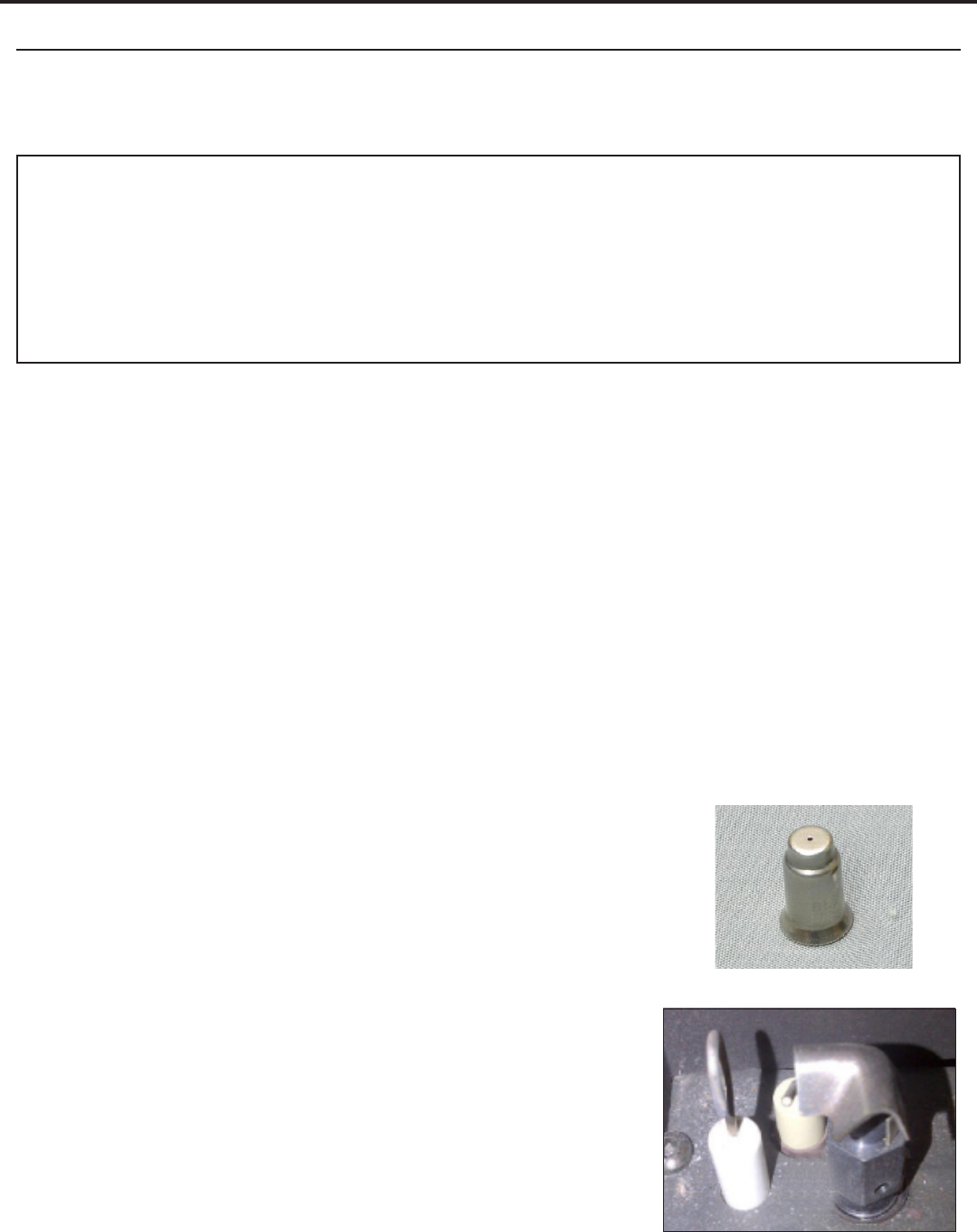
Figure 25: Pilot Orice
Figure 26: Proper Pilot Position
Conversion Kit Installation:
1. Turn the unit o by pressing the ON/OFF Key on the remote and shut o gas supply at the shut-o valve
upstream of the unit. CAUTION: The gas supply must be shut o prior to disconnecting the electrical
power and before proceeding with the conversion. Allow the valve and unit to cool down to room
temperature.
2. Remove the glass door as shown in section “Glass Door Removal” on page 18
3. Carefully remove the log set, and media.
4. Remove the burner as shown in section “Burner Removal” on page
18.
5. Convert the pilot:
a. Using a
7
/16” wrench, loosen the pilot head counter clockwise
and fully remove
b. Remove the existing orice and replace with the one supplied
in the kit (see Figure 25)
c. Re-install the pilot head and tighten until it is back in the proper
position (see Figure 26)
Maintenance And Service
20
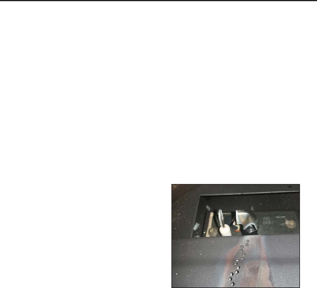
Figure 27: Correct Pilot
Maintenance And Service
6. Convert the burner orice:
a. Remove the main burner orice with a 1/2” socket
b. Put a bead of pipe-thread sealant into the orice mount. DO NOT OVER-TIGHTEN
c. Install the new orice:
7. Convert the SIT gas valve:
a. Use a T-20 driver to remove the two screws that hold the servo regulator to the gas valve and
disconnect the wire harness from the IFC.
b. Remove the rubber regulator diaphragm that is situated between the servo regulator and the valve
body. The new servo regulator already has this diaphragm installed.
c. Install the LP or NG servo regulator, with the new longer T-20 screws included in the kit and connect
the harness to the IFC.
8. Reinstall the burner, log set, media, and glass door. Also refer to section “Installation of Log Set and
Embers” on page 41. When re-installing the burner, ensure that the burner to pilot hood relationship is
similar to what is shown in Figure 27.
9. Reconnect the main gas line if it was disconnected and open the shut-o valve at the gas line to the unit.
10. Reconnect the electrical power to the unit.
11. Use a small brush to apply a warm soapy water solution to all gas connections (use a half dish soap and
half warm water). If a gas leak is present, bubbling will occur. Gas leaks can be repaired by using an
approved pipe thread sealant or approved Teon tape. NEVER USE AN OPEN FLAME WHEN TESTING FOR
LEAKS.
12. Relight the pilot and conrm the ame properly
covers the ame sensor. Should the pilot require
adjustment, turn the adjustment screw (see Figure
63) clockwise to decrease or counterclockwise to
increase until the correct ame is achieved.
13. Relight the main burner in both the “HI” and “LO”
positions to verify proper burner ignition, operation
and proper ame appearance (See Owner’s Manual).
Conrm the inlet and manifold pressures are within
the acceptable ranges as directed in section “Gas
Line Connection and Testing” on page 39.
In the USA: The appliance may be installed at higher altitudes. Please refer to your American Gas
Association guidelines which state: the sea level rated input of Gas Designed Appliances installed at
elevations above 2000 (610 m) feet is to be reduced 4% for each 1000 feet (305 m) above sea level. Refer
also to local authorities or codes which have jurisdiction in your area regarding the de-rate guidelines.
In Canada: When the appliance is installed at elevations above 4500 feet (1372 m), the certied high
altitude rating shall be reduced at the rate of 4% for each additional 1000 feet (305 m).
14. MAKE SURE that the conversion label is installed on or close to the rating label to signify that the unit has
been converted to a dierent fuel type.

21
A. Sidewall to unit 11.125 inches (28.3 cm)
B. Backwall to unit 2.5 inches (6.35 cm)
C. Corner to unit 2.5 inches (6.35 cm)
D. Ceiling 45 inches above oor (114.3 cm)
Minimum Alcove Dimensions:
Width 46 inches (116.8 cm)
Height 45 inches (114.3 cm)
Depth (max) 24 inches (60.96 cm)
CLEARANCES MUST BE SUFFICIENT TO ALLOW ACCESS FOR MAINTENANCE AND SERVICE.
PLanning youR instaLLation
When planning your installation, it will be necessary to select the proper length of vent pipe for your
particular requirements. It is important to note when passing through a wall, the maximum allowable wall
thickness is 10 inches (25.4 cm), 1½ inches (3.8 cm) clearance to combustibles must be maintained. Select
the amount of vertical rise desired for “vertical-to-horizontal” type installations. To determine the length of
vent pipe required for vertical installations, measure the distance from the appliance ue outlet to the ceiling,
the ceiling thickness, the vertical rise through the attic or second story, and allow for sucient vent height
above the roof line. For two story applications, a re stop is required at each oor level. If an oset is needed
in the attic, additional pipe and elbows will be required. To connect the venting system to the appliance ue
outlet, a twist-lock adapter is built into the appliance at the factory. Refer to section “Vent Congurations” on
page 25 for venting parameters.
PRePaRation FoR instaLLation
• Remove the packaging from the appliance, and check to make sure there is no damage. If damage is
found, please report it to both the carrier and your dealer as soon as possible.
• Before beginning, carefully check the glass door and the log set
• Locate a position where the ue system of the stove can be properly installed without damaging the
integrity of the building; e.g. cutting a wall or ceiling joist.
• Check stove and ue system clearance requirements.
• Locate the stove where it can be accessed by a gas supply line.
• Locate the stove in a large and open room that is centrally located in the house. This will optimize heat
circulation and comfort.
• As the stove can be equipped with a convection fan, ensure that an electrical outlet is within 6 ft (1.8 m)
of the stove.
• The ow of combustion and ventilation air must not be obstructed.
cLeaRances to combustibLes
B
A
Front
Back wall
Side wall
C
C
Front
Adjacent wall
Adjacent wall
Figure 28: Clearances to combustibles.
Initial Installation
QUALIFIED INSTALLERS ONLY
Warning: Operation of this heater when not connected to a properly installed and maintained venting
system can result in carbon monoxide (CO) poisoning and possible death.
22
Vertical
Termination
Storm Collar
Flashing
Round Support
Box/Wall Thimble
Ceiling Firestop
Pipelength
Pipelength
Cathedral Ceiling
Support Box
Pipelength
Round Support
Box/Wall Thimble
Pipelength
Horizontal
Termination
90° Elbow
Your total vent pipe length must be within the
shaded area of Figure 34. If a 90° elbow is used
in the horizontal plane, 36” (91.4 cm) must be
subtracted from the allowable horizontal run.
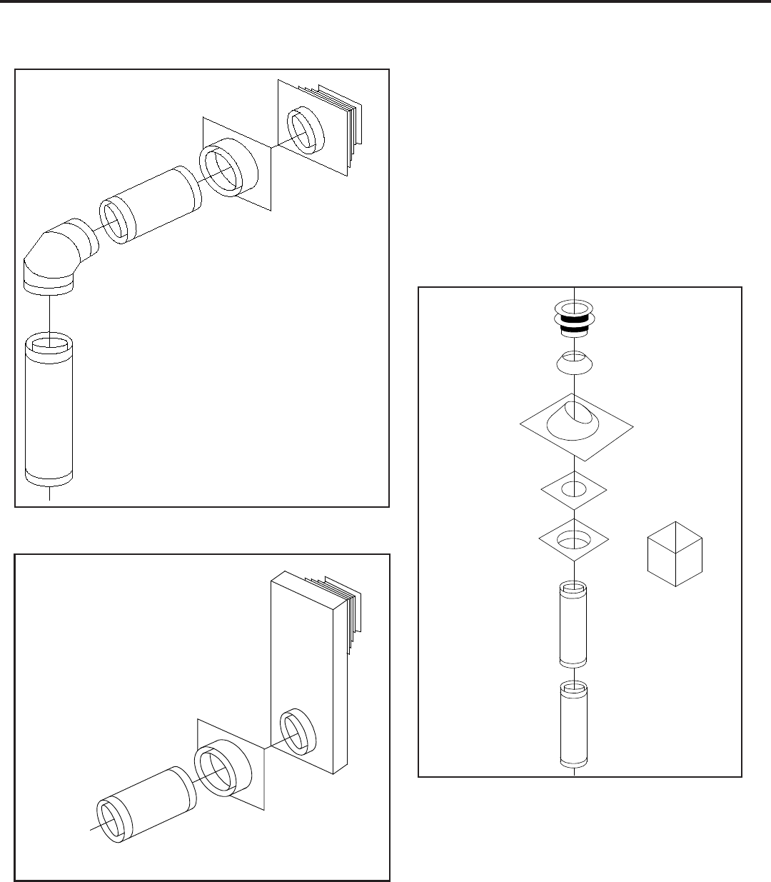
There are three (3) permitted types of Direct Vent
System installations: horizontal (Figure 29), vertical
(Figure 30) or snorkel (Figure 31).
Figure 29: Common Horizontal Installation.
Figure 30: Common Vertical Installation.
Round Support
Box/Wall Thimble
2 ft (610 mm)
Pipelength
36" (915 mm)
Snorkel
Onto Stove
Adaptor
Figure 31: Common Snorkel Installation.
Initial Installation
QUALIFIED INSTALLERS ONLY

23
1
In accordance with the current CSA B149, Natural Gas and Propane Installation Code.
2
In accordance with the current ANSI Z223.1 NFPA 54, National Fuel Gas Code.
* These numbers are only estimates. Clearance in accordance with installation codes and the requirements of the gas supplier.
t
A vent shall not terminate directly above a side walk or paved driveway that is located between two single family dwellings and it serves both dwellings.
+
Permitted only if verandah, porch, deck, or balcony is fully open on a minimum of two sides beneath the oor.
NOTE: Venting terminals shall not be recessed into walls or siding.
Figure 32: Vent Termination Restrictions, refer to Table 3.
vent teRmination RestRictions
A
A
D
E
L
B
C
F
B
B
B
J
M
K
G
H
I
Openable
Fixed
Closed
Openable
Fixed
Closed
Termination Cap
Air Supply Inlet
Gas MeterG
G
Restriction Zone
(Termination not allowed)
N
O
Letter Canadian Installation
1
US Installation
2
Description
A 12 in (30 cm) Clearance above grade, verandah, porch, deck, or balcony.
B 12 in (30 cm) 9 in (23 cm) Clearance from window or door that may be opened.
C 12 in (30 cm)* Clearance from permanently closed window (to prevent
condensation).
D 24 in (60 cm)* Vertical clearance to ventilated sot located above the
terminal, within a horizontal distance of 2 ft (60 cm) from
center line of terminal.
E 18 in (45 cm)* Clearance to unventilated sot.
F 12 in (30 cm)* Clearance to outside corner.
G 12 in (30 cm)* Clearance to inside corner.
H 3 ft (91 cm) within a height of
15 ft (4.5 m) above the meter/
regulator assembly
3 ft (91 cm) within a height of
15 ft (4.5 m) above the meter/
regulator assembly*
Clearance to each side of center line extended above
meter/regulator assembly.
I 3 ft (91 cm) 3 ft (91 cm)* Radial clearance around service regulator vent outlet.
J 12 in (30 cm) 9 in (23 cm) Clearance to non-mechanical air supply inlet to building, or
the combustion air inlet to any other appliance.
K 6 ft (1.83 m) 3 ft (91 cm) above if within 10
ft (3 m) horizontally
Clearance to mechanical air supply inlet.
L 7 ft (2.13 m
)t
7 ft (2.13 m)
*t
Clearance above paved sidewalk or paved driveway located
on public property.
M 12 in / 30 cm
+
12 in / 30 cm*
+
Clearance under verandah, porch, deck, or balcony.
N 12 in (30 cm)* Clearance horizontally to any surface (such as an exterior
wall) for vertical terminations.
O 12 in (30 cm) Clearance above roof line for vertical terminations.
Table 3: Vent termination clearances, refer to Figure 32.
Initial Installation
QUALIFIED INSTALLERS ONLY

24
Direct Vent Direct-Temp DirectVent Pro Description
4D7 (7”) 4DT-06 46DVA-06 6” Pipe Length
4DT-09 46DVA-09 9” Pipe Length
4D2 4DT-12 46DVA-12 12” Pipe Length
4DT-18 46DVA-18 18” Pipe Length
4DT-24 46DVA-24 24” Pipe Length
4D3 4DT-36 46DVA-36 36” Pipe Length
4D4 4DT-48 46DVA-48 48” Pipe Length
46DVA-60 60” Pipe Length
4D26A 4DT-TL14 46DVA-24TA Adjustable Length
4D45L 4DT-EL45 46DVA-E45 45° elbow
4D90L 4DT-EL90S 46DVA-E90 90° elbow
4DHVS 4DT-VS 46DVA-VSS
Vinyl siding
stando/sheild
4DWT 4DT-WT 46DVA-WT Wall thimble
4DSC 4DT-SC 46DVA-SC Storm collar
4DFSP 4DT-FS 46DVA-WFS Fire stop
4DWS 4DT-WS 46DVA-WS
Wall strap/
support/band
4DF 4DT-AF6 46DVA-F6
Flashing, standard
roof pitch
4DF12 4DT-AF12 46DVA-F7
Flashing, steep
(up to 12/12) roof
46DVA-FF Flat ashing
46DVA-VCH
High wind vertical
termination
4DHCS 4DT-HC 46DVA-HC
High wind
horizontal
termination
4DT-HKA / 4DT-HKB 46DVA-KHC
Horizontal
termination kit
4DT-CCKA 46DVA-KCA
Chimney
Conversion Kit A
4DRCKA 4DT-CCKB 46DVA-KCB
Chimney
Conversion Kit B
46DVA-KCC
Chimney
Conversion Kit C
aPPRoveD vent PaRts
Table 4: Vent part numbers (Must state if galvanized or black wanted, PART NUMBERS).
WARNING: Do not mix parts from dierent vent manufacturers’ systems.
EXCEPTION TO WARNING: This product has been evaluated by Intertek for using a DirectVent Pro starting
collar in conjunction with other venting systems. Use of this system with the DirectVent Pro starting collar is
deemed acceptable and does not aect the Intertek listing of the appliance.
Approved
Termination Cap
Top Adapter
Existing Metal
Chimney
System
4-inch
pipe
Any black
direct vent
pipe plus an
adjustable
length
to make
a proper
connection
Conversion
Connector
USA ONLY
Initial Installation
QUALIFIED INSTALLERS ONLY

25
to disrupt air movement. Using 45˚ elbows is preferable to
using 90˚ elbows. Also, a shorter vent system will perform
better than a longer one.
vent conFiguRations
Figure 34 & Figure 35 show the range of venting options, they show possible vent congurations if the unit is
top vented (see Figure 34) or rear vented (see Figure 35), for vertical and horizontal terminations, any layout
that remains within the shaded area is acceptable. Having the fewest number of elbows is ideal, as they tend
Figure 33: Possible Vent Congurations for Rear
Vented; Vertical and Horizontal Terminations.
*NOTE: 0,0 in Figure 34
& Figure 35 represent the
outlet of the ue collar
elbow.
Initial Installation
QUALIFIED INSTALLERS ONLY
Figure 34: Possible Vent Congurations for Top Vented; Vertical and Horizontal
Terminations.

26
The ENVIRO CUBE has been designed with a built in restrictor plate. The restrictor is designed to enhance
ame appearance when installing this unit with vertical chimneys as well as installations with longer horizontal
vent applications. It does this by controlling the amount of air moving through the vent pipe.
Figure 34 shows the vent restrictor position required, relative to the length of vent pipe. Longer vertical vent
lengths necessitate greater restriction; position 1 (Figure 36) is open and position 5 (Figure 37) is maximum
restriction. To avoid injury, it is best to make this adjustment when the replace is cool or use welder’s gloves
or oven mitts.
To access vent restrictor remove the valve cover plate from the right rear corner of the unit by undoing the
four fastening screws. Refer to Figure 35.
Loosen the ¼” hex head screw and adjust to the correct setting.
Slide the hex head screw to the next setting and re-tighten the screw to secure in place.
The numbers in this chart represent the actual vent restrictor settings. Although the numbers do not appear
on the unit use this as a guide to follow.
Wait for unit to warm up to operating temperature to ensure proper and clean burning unit.
Initial Installation
QUALIFIED INSTALLERS ONLY
RestRictoR settings
1
2
3
4
5
1
2
3
4
5
Figure 35: Restrictor Adjustment Location
Figure 36: Restrictor Setting 1
Figure 37: Restrictor Setting 5

27
hoRizontaL instaLLation
1. Set the appliance in the desired location. Check to determine if wall studs or roof rafters are in the way
when the venting system is attached. If this is the case, you may want to adjust the location of the
appliance.
2. Direct vent pipe and ttings are designed with special twist-lock connections. Assemble the desired
combination of black pipe and elbows to the appliance adapter with pipe seams oriented towards the wall
or oor, as much out of view as possible.
Note: Horizontal runs of vent pipe must be supported every 36” (915mm). Wall straps are available for this
purpose, also when running horizontal pipe minimum clearances to combustibles must be maintained; 2”
(51mm) at top, 1½” (38mm) at sides, 1½” (38mm) at bottom.
3. With the pipe attached to the stove in the correct location, mark the wall for a 10” (25.4cm) x 10” (25.4
cm) square hole (refer to Figure 38). The center of the square hole should match the center line of the
horizontal pipe. Cut and frame the 10” (25.4cm) x 10” (25.4cm) hole in the exterior wall where the vent
will be terminated. Refer to Figure 32 and Table 3 for allowable locations. If the wall being penetrated is
constructed of non-combustible material i.e. masonry or concrete, a 7” (17.8cm) hole is acceptable.
4. Position the horizontal vent termination in the center of the 10” (25.4cm) x 10” (25.4cm) hole, and
attach to the exterior wall with the four screws provided. Before attaching the vent termination to the
exterior wall, run a bead of non-hardening mastic around the edges, so as to make a seal between the
Woodscrews
Wall Thimble
Strap
Sheet metal
screws
Fold strap
here
1
1
/4"
(3.2cm)
10"
(254mm)
10"
(254mm)
Figure 38: Wall Framing Hole for
Horizontal Installation.
termination and the wall. The arrow on the vent termination should be
pointing up, insure that the proper clearances to combustible materials
are maintained.
5. Before connecting the horizontal run of the vent pipe to the vent
termination, slide the black decorative wall thimble cover over the vent
pipe.
6. Slide the appliance and vent assembly towards the wall, carefully
inserting the vent pipe into the cap assembly. It is important that the
vent pipe extend into the vent cap a sucient distance with a minimum
of 1¼” (3.2cm) overlap. Secure the connection between the vent cap
pipe and the vent cap by attaching the two sheet metal straps extending
from the vent cap assembly into the outer wall of the vent pipe. Use the
two sheet metal screws provided to connect the straps to the vent pipe.
Bend any remaining portion of the sheet metal straps back towards the
vent cap, so the decorative wall thimble will conceal it (see Figure 39).
7. Slide the decorative wall thimble up to the wall surface and attach with
Initial Installation
QUALIFIED INSTALLERS ONLY
the screws provided.
Figure 39: Installing Decorative Wall Thimble.

28
Wood screws (x4)
Cut vinyl siding
away to fit standoff
Bolt (x4)
required
Nut (x4)
required
Wood
screw (x4)
Figure 40: Installing Vent Cap with Vinyl Siding
Stand-O.
Figure 41: Installing Horizontal Vent
Termination.
NOTES:
(a) The four (4) wood screws provided should be replaced with the appropriate fasteners for stucco, brick,
concrete, or other types of siding.
(b) For buildings with vinyl siding, a vinyl siding stando, should be installed between the vent cap and the
exterior wall (see Figure 40). Attach the vinyl siding stando to the horizontal termination. The vinyl siding
stando prevents excessive heat from possibly melting the vinyl siding material. Note that the horizontal vent
termination bolts onto the at portion of the vinyl siding stando (shaded area in Figure 40), so that an air
space will exist between the wall and the vent termination.
(c) The horizontal run of vent pipe must be level and should have a ¼ inch rise for every one foot of
run towards the termination. Never allow the vent to run downward. This could cause high temperature
and may present the possibility of a re.
(d) The location of the horizontal vent termination on the exterior wall must not be easily blocked or
obstructed. Refer to section “Vent Congurations” on page 25.
(e) When installing a vent pipe in a chase the minimum clearance to combustibles is 2” (51 mm).
(f) Maintain manufacturer’s clearances to combustibles with venting.
Initial Installation
QUALIFIED INSTALLERS ONLY

29
3. To install the Round Support Box/Wall Thimble in
a at ceiling, cut a 10” square hole in the ceiling,
centered in the hole drilled in Step 2. Frame the
hole as shown in Figure 42.
4
. Assemble the desired lengths of black pipe and
elbows necessary to reach from the appliance
adapter up through the Round Support Box. Insure
that all pipe and elbow connections are in their fully
twist-locked position.
5.
Cut hole in the roof centered on the small hole
placed in the roof from Step 2. The hole should be
of sucient size to meet minimum requirements for
Clearance to Combustibles, as specied. Continue
to assemble lengths of pipe and elbows necessary
to reach from the ceiling support box up through
the roof line. Galvanized pipe and elbows may be
utilized in the attic, as well as above the roof line.
1
1
/
2
” (4cm) long
wood screw (x4)
10” (25.4cm) x 10” (25.4cm)
inside framing
Ceiling Joist
Framing
Figure 42: Wall Framing for Hole for Vertical
Installation.
The galvanized nish is desirable
above the roof line, due to the
higher corrosion resistance.
6.
Once the pipe sections have been
joined, and run up through the hole
in the roof, slip an elbow strap over
the exposed sections, bend the
support straps outwards, and push
the elbow strap down to the roof
level, as shown in Figure 43. Tighten
the clamp around the pipe section.
Use a level to make sure the pipe
is truly vertical. With roong nails,
secure the support straps to the
roof. Seal the nails holes heads with
non-hardening mastic. Trim the
excess length of the support straps
that extend out beyond the edge of
the ashing.
veRticaL instaLLation
1. Check the instructions for required clearances (air spaces) to combustibles when passing through ceilings,
walls, roofs, enclosures, attic rafters, or other nearby combustible surfaces. Do not pack air spaces with
insulation.
2
. Set the gas appliance in the desired location. Drop a plumb bob down from the ceiling to the position of
the appliance ue exit, and mark the location where the vent will penetrate the ceiling. Drill a small hole
at this point. Next, drop a plumb bob from the roof to the hole previously drilled in the ceiling, mark the
spot where the vent will penetrate the roof. Determine if ceiling joists, roof rafters, or other framing will
obstruct the venting system. You may wish to relocate the appliance, or to oset, to avoid cutting load
bearing members.
Vertical
Termination
Storm Collar
Flashing
Roofing nails
Elbow Strap
Figure 43: Vertical Vent Termination Installation.
Initial Installation
QUALIFIED INSTALLERS ONLY

30
7. Slip the ashing over the pipe section protruding through the roof. Secure the base of the ashing to the
roof with roong nails. Use a non-hardening sealant between the uphill edge of the ashing and the roof.
Insure the roong material overlaps the top edge of the ashing as shown in Figure 43. Verify that you
have at least the minimum clearance to combustibles at the roof line.
8.
Continue to add pipe sections until the height of the vent cap meets the minimum code requirements.
Refer to Figure 44 and Table 5. Note that for steep roof pitches, the vent height must be increased. In
high wind conditions, nearby trees, adjoining roof lines, steep pitched roofs, and other similar factors can
result in poor draft, or down drafting. In these cases, increasing the vent height may solve the problem.
9.
Slip the storm collar over the pipe, and push it down to the top of the roof ashing as shown in Figure 43.
Use the non-hardening sealant around the joint between the pipe and the storm collar.
10. Twist-lock the vent cap.
H
Dimension ‘H’ obtained
from table below.
Table 5: Minimum ‘H’ for Figure 44.
Roof Pitch Minimum Height
Feet Meters
Flat to 7/12 1 0.3
Over 7/12 to 8/12 1.5 0.46
Over 8/12 to 9/12 2 0.61
Over 9/12 to 10/12 2.5 0.76
Over 10/12 to 11/12 3.25 0.99
Over 11/12 to 12/12 4 1.22
Over 12/12 to 14/12 5 1.52
Over 14/12 to 16/12 6 1.83
Over 16/12 to 18/12 7 2.13
Over 18/12 to 20/12 7.5 2.29
Over 20/12 to 21/12 8 2.44
Figure 44: Height of Vertical Termination; Reference
Table 5.
NOTES:
(a)
If an oset is necessary in the attic to avoid obstructions, it is important to support the vent pipe every 3
feet (91 cm), to avoid excessive stress on the elbows, and possible separation. Wall straps are available
for this purpose (see Figure 45).
(b) When ever possible, use 45° degree elbows instead of 90° degree elbows. The 45° degree elbow oers
less restriction to the ow of ue gases and intake air.
(c)
For multi story installations. A ceiling restop is required at the second oor, and any subsequent oors
(see Figure 46). The opening should be framed to 10” (25.4 cm) x 10” (25.4 cm) inside dimensions, in
the same manner as shown in Figure 42.
(d) Any occupied areas above the rst oor, including closets and storage spaces, which the vertical vent
passes through, must be enclosed. The enclosure may be framed and sheet rocked with standard
building materials. However consult the appliance manufactures installation instructions for the minimum
allowable clearance between the outside of the vent pipe, and the combustible surfaces of the enclosure.
Do not ll any required air spaces with insulation.
Initial Installation
QUALIFIED INSTALLERS ONLY

31
plumber’s tape
connected to
wall strap
Wall strap
45° elbows (x2)
Nails
Ceiling firestop
Ceiling
Second floor
Use clearances to as
defined by appliance and
vent pipe manufacturers.
catheDRaL ceiLing instaLLation
Figure 45: Use of Wall Straps.
Figure 46: Multi-Story Vent Pipe Installation.
Figure 47: Cathedral Ceiling Support Box Leveling.
1. Follow installation steps 1 & 2 under section
“Vertical Installation” on page 29.
2.
Using the plumb bob, mark the centerline of the
venting system on the ceiling and drill a small
hole through the ceiling and roof at this point.
From the roof, locate the drill hole and mark the
outline of the “Cathedral Ceiling Support Box”.
3.
Remove shingles or other roof coverings as
necessary to cut the rectangular hole for the
“Support Box”. Cut the hole ⅛” larger than the
“Support Box” outline.
4.
Lower the “Support Box” through the hole in
the roof until the bottom of the “Support Box”
protrudes at least 2 inches (5 cm) below the
ceiling. Align the “Support Box” both vertically
and horizontally with a level as shown in Figure
47. Temporarily tack the “Support Box” in the
place through the inside walls and into the roof
sheathing.
Initial Installation
QUALIFIED INSTALLERS ONLY

32
Figure 48: Cathedral Ceiling Support Box
Installation.
Figure 49: Corner installation rear vented with
snorkel.
Figure 50: Corner installation top vented.
coRneR instaLLations
Do not interfere with the structural integrity of the walls.
When rear venting if a 90° bend is used the maximum horizontal vent that can be used is 6” (152mm) and
if a 45° bend is used the maximum horizontal vent that can be used is 12” (305mm). For installations with
a 36” (915 mm) snorkel refer to Figure 49 and section “Vent Congurations” on page 25. For other corner
installations refer to Figure 50 and section “Vent Congurations” on page 25.
5.
Using tin snips, cut the “Support Box” from the top corners
down to the roof line, and fold the resulting aps over the
roof sheathing (Figure 48). Before nailing it in to the roof, run
a bead of non-hardening mastic around the top edges of the
“Support Box”, to make a seal between the box and the roof.
Clean out any combustible material from the inside of the
“Support Box”.
6.
Complete the cathedral ceiling installation by following the
same procedures outlined in Steps 4 through 9 in section
“Vertical Installation” on page 29.
Initial Installation
QUALIFIED INSTALLERS ONLY

33
Initial Installation
QUALIFIED INSTALLERS ONLY
conveRting toP venteD into ReaR venteD
This unit can be converted to a rear vented unit with a 36” (915mm) snorkel for some installation applications.
To convert this unit to a rear vented model, the ue pipe adapter must be turned to the rear vent position:
1. Remove the top plate as shown in section “Back Cover and Top Plate Removal” on page 17.
2. Remove the four (4) #8 hex head screws holding the ue pipe adapter in place (see Figure 51).
3. Rotate the ue adapter 180° so that the end of the adapter is now pointing out the rear of the unit.
4. Reattach the ue adapter using the same screws that were removed in Step 2.
5. Reattach the top cover.
6. Find the rear vent cap that was included with the unit. Align the rear vent cap as shown in Figure 52 and
fasten into place using two (2) #8 screws.
Figure 51: Flue Pipe Adapter - Rear Vent Conversion
Figure 52: Top Vent Cover Plate
*Back cover hidden for clarity
34
instaLLation oF ReaR venteD aPPLiance
Siding
Exterior wall
Drywall
Vent pipe
Inside finished collar
Minimum vent terminal 36"
(91.4cm) high snorkel kit.
Wall thimble
Figure 53: Installation for Rear Vented;
1. Place the unit into position.
2. Attach a small section of pipe on the unit and mark exterior
wall where vent would pass through the wall.
3. Cut a 10” (25.4 cm) minimum hole in the wall to maintain
clearances to combustibles. Frame hole as shown in Figure
38.
4. Install a wall thimble.
5. Install interior nished collar.
6. Install the vent section through the wall.
7. Seal around the vent terminal to the structure using a non
hardening mastic.
Also refer to section “Vent Congurations” on page 25.
Initial Installation
QUALIFIED INSTALLERS ONLY
Siding
Exterior wall
Drywall
Vent pipe
Inside
finished collar
Wall thimble
Termination
Figure 54: Installation for Top
Vented; Horizontal Termination.
instaLLation oF toP venteD; hoRizontaL teRmination
This is the most common type of installation style.
Set the unit in place.
Install a minimum 24” (61 cm) vertical chimney.
Install a 90° elbow, and mark the exterior wall where the vent would
pass through.
Cut a 10” (25.4 cm) minimum hole in the wall to maintain clearances
to combustibles around vent pipe. Frame hole if as shown in Figure 38.
Install wall thimble.
Install interior nished collar
Install the vent section through the wall and then install the vent
termination.
Seal around the termination using a non hardening mastic.
CORNER INSTALLATION:
This type of installation can be used in a corner installation. If a 90°
elbow is used in the horizontal plane, 36” (91.4 cm) must be subtracted
from the allowable horizontal run shown in Figure 34.

35
instaLLation oF toP venteD; veRticaL teRmination
Vent cap
Roof flashing
Roof
truss
Flue pipe
Insulation
gaurd
Ceiling
support
Inside
finished collar
Figure 55: Installation for Top Vented; Vertical
Termination.
Place the unit in place.
Drop a plumb bob from the ceiling to the center point of
the ue outlet.
Cut a 10” (25.4 cm) hole in the ceiling and the roof. Refer
to Figure 42.
Install the ceiling support and insulation guard.
Install the roof ashing. Ensure that the roof ashing is
installed under the roong material so that a watertight
seal is created.
Install the ue pipe from the top of the unit through the
roof.
Ensure that all ue pipe and unit maintain required
clearances to combustibles.
CORNER INSTALLATION:
This type of installation can be used in a corner installation.
If a 90° elbow is used in the horizontal plane, 36” (91.4
cm) must be subtracted from the allowable horizontal run
shown in Figure 34.
Initial Installation
QUALIFIED INSTALLERS ONLY
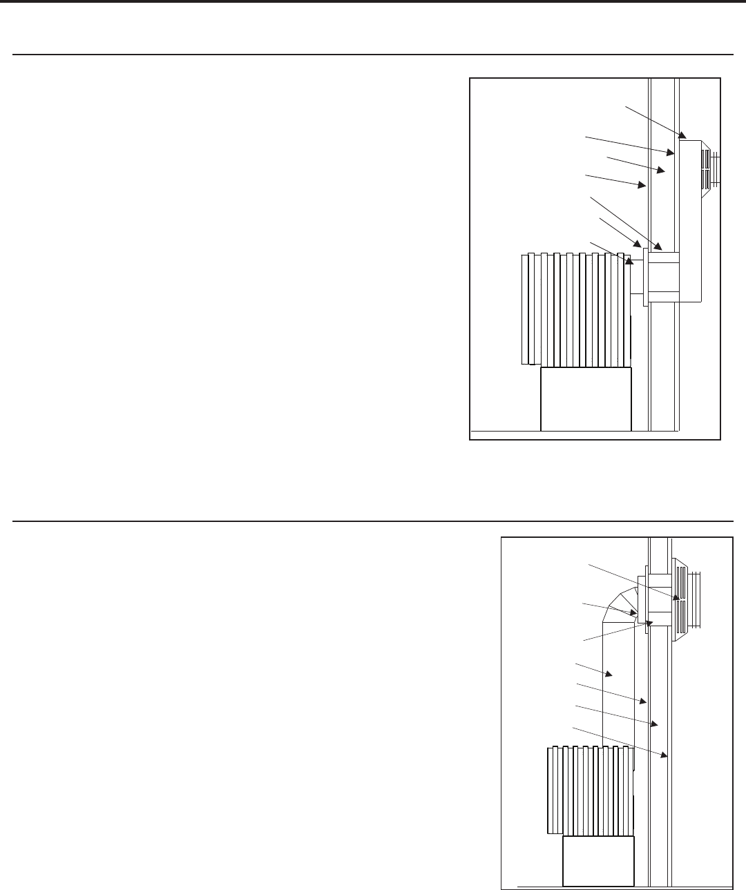
FReestanDing DRaFthooD aDaPtoR - (50-841 & 50-4176)
This Drafthood Adaptor is a complete assembly and is ready to t onto the Cube in a vertical vent application
only. With the Drafthood Adaptor correctly installed and wired to the IFC the Cube may be vented like a
B-Vent Fireplace.
INSTALLATION:
WARNING: This Freestanding Drafthood Adaptor must be tted by a qualied service technician.
1. Remove the Drafthood Adaptor from the packaging. Ensure the unit and wire harness are undamaged. If
there is damage contact your dealer, distributor, or courier company before starting this installation.
2. Install the adaptor so the wires exit to the rear of the replace. Slide the Drafthood Adaptor over the
outlet pipe of the replace until the bottom of the adaptor collar stops on the top of the outlet. The
Drafthood Adaptor must be safely secured to the vent anges with either self-tapping screws and/or high
temperature sealant.
WARNING: During the tting of the Drafthood Adaptor, ensure that the wires are not pinched between the
adaptor and the collar and/or ue outlet. Ensure that the opening of the Drafthood Adaptor is not blocked
or obstructed.
3. Being careful not to run any wiring tight across metal edges; connect them to the X4 terminal block on
the IFC (see wiring section).
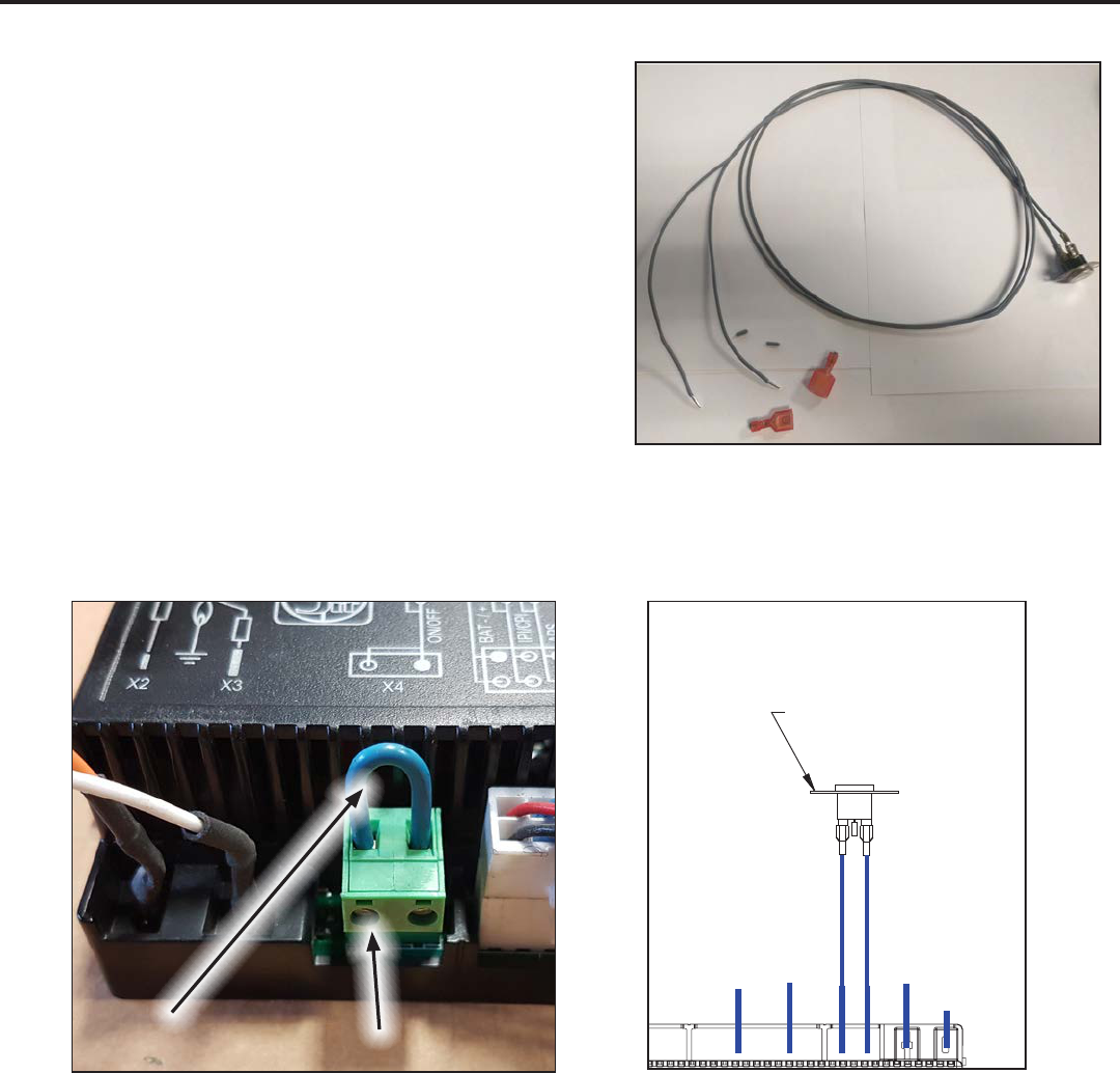
36
Figure 56: Spill Switch Modication
DRAFTHOOD WIRING:
In order to connect the Drafthood Adaptor to the IFC the
spill switch wires must rst be modied as instructed below.
Step 1: Cut o the connectors from the one end of the
wires. Note, the spill switch does not need to be removed
from the Drafthood Adaptor for this modication (Figure
56).
Step 2: Strip o approx. 1/4” of insulation from the wire
ends.
Step 3: Remove the ON/OFF terminal block from the X4
port on the IFC (Figure 50).
Step 4: Using a small at blade screwdriver loosen the set
screws on the terminal block and remove the wire loop/
jumper. The wire jumper can be discarded
Initial Installation
QUALIFIED INSTALLERS ONLY
Figure 57: ON/OFF Terminal Block on IFC
Figure 58: Spill Switch Wiring Diagram
Set Screws
Wire Jumper
[Remove]
GENERAL VENTING INFORMATION:
Canadian Installations
The venting system must be installed in accordance with the current CSA B149.1 installation code and/or
local codes having jurisdiction.
U.S.A. Installations
The venting system must be installed in accordance with the current National Fuel Gas Code, ANSI Z223.1/
NFPA 54, and/or local codes having jurisdiction. It is strongly recommended to install an approved chimney
liner in an existing brick chimney. This will maximize the potential draft of the chimney and lessen the eects
of slow chimney start-up.
Venting and any combustibles when using 4” (10 cm) single wall exible venting.
IFC (50-3202) /
(0.584.326)
Main On/Off
(50-3205)
Drafthood adaptor
300
o
F (149
o
C)
manual reset
temperature
sensor
Step 5: Insert the sripped spill switch wires into the ON/OFF terminal block and tighten the set screws.
Note: There is no polarity to the spill switch wires so it will work in either position of wires (Figure 51).

37
Figure 59: Unit top venting
styles.
4" (10cm)
vent
6" (15cm)
optional
decorative
cover
Check vent
draft at the
top row of
opening.
Figure 60: Unit rear
venting style.
VENTING OF A FIREPLACE FITTED WITH THE DRAFTHOOD ADAPTOR:
Note: Please refer to the chimney manufacturer’s installation instructions prior to commencing the installation.
This unit may be vented to an existing masonry chimney, or where no masonry chimney is available, an
approved “B-vent” chimney, or any other approved constructed chimney/vent system (see Figure 52 & 53).
In either case, the replace may be connected to the chimney/vent using a 4” (10 cm) single wall vent
connector.
When an existing masonry chimney is utilized for the venting, we recommend the vent connector be connected
to an approved 4” (10 cm) diameter ue liner running the full height of
the chimney. In many jurisdictions this ue liner may be mandatory.
If 4” (10 cm) single wall vent is used, a minimum of 6” (15 cm) must be
maintained between the vent connector and any combustibles.
If 4” (10 cm) “B-vent” is used a minimum of 1” (25 mm) must be
maintained between the vent connector and any combustibles.
CAUTION: A minimum vent height of 12’ (3.6 m) from the oor is
required to eectively vent this replace.
SPILLAGE TEST:
A spillage test must be performed prior to leaving the installed replace
with the customer. Perform this test in the following manner:
1. Close all windows and doors in the room.
2. Start all exhaust fans in the house and the furnace blower.
3. Light the replace and set to maximum ame adjustment.
Initial Installation
QUALIFIED INSTALLERS ONLY
Figure 61: Draft test place.
4. After a minimum of 10 minutes operation,
test the chimney draft with a smoke
match at the top row of the pattern to
conrm that there is adequate draft or
‘pull’ at the openings around the body
of the Drafthood Adaptor, as shown in
Figure 54.

38
AUTOMATIC SAFETY SHUT DOWN:
If the spill switch is activated and shuts o the main burner the following procedure should be followed.
• Is the pilot ame still on? If not, the reason for the replace shut down is not the spill switch.
• Turn o the pilot ame and turn o all controls. Let replace to cool down.
• Check for blockages or restrictions in the ue and venting components.
• Restart the replace and check for vent draft as described earlier.
• Operate the replace in a normal manner.
• If the main burner shuts down again after a period of operation, turn o the replace and contact your
service technician.
Figure 62: Spill switch installation.
Initial Installation
QUALIFIED INSTALLERS ONLY
SPILL SWITCH REPLACEMENT:
Use the following instructions to replace the Safety
Spill Switch.
1. Turn the unit o and allow it to cool.
2. Disconnect the spill switch wires from the IFC
(see Figures 50 & 51).
3. Remove the four mounting screws holding the
spill switch bracket and remove the bracket (see
Figure 55).
4. Remove and replace the spill switch with a 50-
885 Spill Switch Assembly using a T-20 torx type
driver.
5. Follow the reverse of the previous steps.
OPTIONAL FINISHING:
In installations where the ue connector is running from the drafthood into a non-combustible chimney the
following optional nishing technique can be used.
CAUTION: Installations where the ue connector or venting connects to, or passes through,
combustible walls or ceilings, the inner vent components must be ‘B-vent’. It is not allowable
in these applications to use single wall inner vent components.
For decorative purposes a 6” (15 cm) single wall black stove pipe may be installed over the 4” (10 cm) single
wall or ‘B-Vent’.
Note: The use of these components is for aesthetic purposes only and does not eect the fact
that the replace, when tted with the Drafthood Adaptor, is a Natural Vent appliance and
therefore draws air in through the Drafthood Adaptor intake ports.

39
gas Line connection anD testing
WARNING: Only persons licensed to work with gas piping may make the necessary gas connections to this
appliance.
GAS LINE CONNECTION
• This stove is equipped with a certied exible pipe located on the right side of the unit terminating in a
⅜” male NPT tting. Consult your local authorities codes or the CAN/CGA B 149 (1 or 2) installation code
in Canada, or in the USA gas installations follow either local
codes or the current edition of the National Fuel Gas Code
ANSI Z223.1.
• The eciency rating of this appliance is a product
thermal eciency rating determined under continuous
operating conditions and was determined independently of
any installed system.
The appliance and its shuto valves must be disconnected
from the gas supply piping system during any pressure
testing where the pressure exceeds ½ PSIG (3.45 KPa) or
damage will occur to the valve.
The appliance must be isolated from the gas supply piping system by closing its individual manual shuto
valve during any pressure testing of the gas supply piping system at test pressures equal to or less than ½
psig (3.45 KPa).
Always check for gas leaks with a soap and water solution after completing the required
pressure test.
TO TEST VALVE PRESSURES
The pressure taps are located on the left side of the valve
• Turn set screw 1 turn counter clockwise to loosen,
• Place
5
/16” (8 mm) I.D. hose over pressure tap system.
• Check pressures using a manometer.
• When nished, release pressure, remove hose & tighten set screw.
Table 6: Pressure and BTU Information.
Natural Gas Propane
Main Burner #39 DMS #53 DMS
Manifold Pressure 3.8” W.C. / 0.95KPa 11.0” W.C. / 2.7KPa
Min. Manifold Pressure 1.2” W.C. / 0.29KPa 2.9” W.C. / 0.72KPa
Max Supply Pressure 7.0” W.C. / 1.74KPa 13.0” W.C. / 3.28KPa
Min. Supply Pressure 5” W.C. / 1.24KPa 12.0” W.C. / 2.98KPa
Max BTU/hr Input 30,000 BTU/hr (8.80KW) 26,500 BTU/hr (7.76KW)
Min. BTU/hr Input 17,000 BTU/hr (4.98 KW) 14,000 BTU/hr (4.10KW)
Venturi Setting
1
/16” min.
3
/16” min.
NEVER USE AN OPEN FLAME FOR LEAK TESTING.
Pilot Adjustment
Screw
Manifold
Pressure Tap
Inlet
Pressure Tap
Stepper
Regulator
Figure 63: Fully Labeled Gas Valve.
Initial Installation
QUALIFIED INSTALLERS ONLY
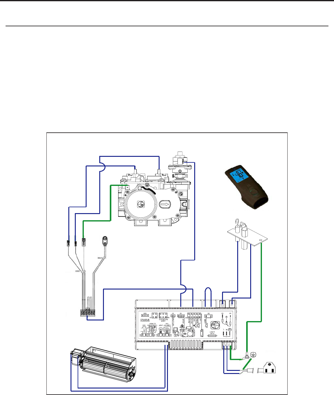
40
eLectRicaL RequiRements
The replace must be electrically connected and grounded in accordance with local codes or, in the absence
of local codes, with the current CSA C22.1 Canadian Electrical Code Part 1, Safety Standards For Electrical
Installations, or The National Electrical Code ANSI / NFPA 70 in the US.
WARNING: The electrical grounding instructions must be followed. The fan kit is equipped with a three-
prong (grounding) plug for your protection against shock hazard, and should be plugged directly into a
properly grounded three-prong outlet. DO NOT cut or remove the grounding prong from this plug.
CAUTION: When servicing controls, label all wires prior to disconnection. Wiring errors can cause improper
and dangerous operation. Verify proper operation after servicing.
If any of the original wire as supplied with the appliance must be replaced, it must be replaced with 18
AWG wire with a temperature rating of 105°C
IFC
Main
Harness
Transmitter - TMFLSA
885 Gas Valve
IPI Pilot
Convection Fan
Proflame 2 System - Wiring Diagram
Main
On/Off
Power Cord
To
Battery
Holder
Flame Sensor
Spark Electrode
Figure 64: Wiring Diagram
Initial Installation
QUALIFIED INSTALLERS ONLY

41
instaLLation oF Log set anD embeRs
The placement of the logs is not arbitrary. If they are positioned incorrectly, the ames can be “pinched” and
will not burn correctly. The burner come with four (4) locator pins, and the right log has two (2) ledges which
make alignment easier. Using the pictures provided, carefully set the logs in place.
NOTE: The logs are fragile and
should be handled gently.
CAUTION: Use only the type of
ember material supplied with this
appliance. Due to the irregular size
of the ember material there may be
more than required. The use of other
foreign materials on the burners may
create dangerous conditions.
If over time, through cleaning and
servicing, these embers require
replacement, contact the nearest
ENVIRO dealer for replacement
embers.
Note: Log set shown with optional
panel set (50-1038) installed.
Figure 65: Optional Fan Kit Installation.
instaLLation oF oPtionaL Fan kit (50-4304)
1. Remove the pre-assembled fan assembly from the
packaging. Inspect the fan for damage. If damage
is noticed call your dealer, distributor or courier
company and have components replaced.
2. Align the fan kit with the rectangular hole in the
table/long table, bend the anges, and secure with
#8 T20 screws.
3. Follow the wiring instructions supplied with the kit
and complete installation.
Refer to the installation instructions included
with the fan kit for additional details.
Secondary Installation
Figure 66: Step 1 of Log Placement.
Figure 67: Step 2 of Log Placement.

42
1. Carefully remove logs from box.
Check to ensure there is no damage.
It is very important to install all logs
in their proper position to insure
safe, optimum operating conditions.
2. Place the log set into the rebox.
Locate each log by seating it down
onto the burner tray support pins.
Follow Figure 66 to Figure 72 proper
log placement.
3. A bag of ceramic ber embers
and rock wool embers is provided
gently remove the ember material
from the plastic bag. Spread a
layer loosely in a random manner
across the burner tray. Do not allow
any embers to rest against pilot
assembly. (See diagram provided
for proper ember placement.)
DO NOT pack this ember material
as this could create an unsafe
condition, leave embers loose.
4. Upon the rst light up, watch for
ignition to ALL burner ports. If a
long delay is noted: First, wait for
the appliance to cool down.
• Open the front door of the
appliance.
• Check to carefully reposition the
embers making sure that burner
ports are not plugged solid or
blocked.
Figure 68: Step 3 of Log Placement.
Figure 69: Step 4 of Log Placement.
Figure 70: Complete Log Placement.
Secondary Installation

43
CAUTION: NEVER OPERATE THIS APPLIANCE WITH THE GLASS DOOR REMOVED.
Important note: When the unit is turned on
for the rst time, It should be turned onto high
without the fan on for the rst four (4) hours.
This will cure the paint, logs, gasket material and
the other products used in the manufacturing
process. It is advisable to open a window or door,
as the unit will start to smoke and can irritate
some people. After the unit has gone through the
rst burn turn the unit o including the pilot, let
the unit get cold then remove the glass door and
clean it with a good gas replace glass cleaner,
available at your local ENVIRO dealer.
See section “Cleaning The Glass” on page 16
for details on how to remove door to clean glass.
Figure 71: Log Placement with Rock Wool.
Secondary Installation
Figure 72: Log Placement with Rock Wool & Embers.
Figure 73: Appliance Burning.

44
Figure 74: Panel bracket, slots shown.
1. Remove the two (2) screws from the rear of
the bae, use a ¼” socket. Place the panel
bracket (Figure 74) at the rear of the bae
with the slots over the screw holes (see
Figure 75). Insert two (2) of the provided
screws into the two (2) holes along the
bottom of the bae.
2. Remove the two (2) screws from the front
of the bae. Slide the top brick panel into
the bottom bracket and place the other
bracket over the top of the panel and line
up the slots on the bracket with the holes
at the top of the bae. Use two (2) of the
provided screws to hold the bracket in place.
Ensure the top panel is centered before
tightening the four (4) screws completely
(refer to Figure 75).
3. Slide each side brick panel into place along
the sides of the rebox. The panels should
rest ush with the back and sides of the
rebox (refer to Figure 77).
instaLLation oF oPtionaL PaneL set (50-1038)
Do not install when the unit is hot.
The panel set is fragile. Handle panels with care and avoid knocking them on the placement
pins or any other object.
Secondary Installation
Figure 75: Top panel placement, screws shown.
Figure 76: Side brick panel placement.

45
RemovaL oF saFety scReen
If necessary, the safety screen can be removed from its assembly for cleaning or replacement by following
the steps below.
1. Turn o the stove and allow it to fully cool down.
2. Remove the safety screen assembly from the unit. Refer to section “Screen and Outer Glass Removal”
on page 16
3. Lay the screen assembly face down on a soft surface to prevent scratching the paint.
4. Remove the two (2) #8 T20 screws on the inner top face of the assembly (see Figure 78).
5. Unbend the two (2) hand tabs on the outer bottom face of the assembly (see Figure 78).
6. Remove the left and right inner trim pieces from the assembly. This will free the safety screen allowing
it to also be removed.
To re-install the safety screen simply reverse the procedure.
Figure 77: Safety Screen Removal
Secondary Installation

46
Trouble Shooting
Problem Possible Cause Solution
The main burner does not
ignite when called for.
The gas valve may not be on. • Check that the gas control knob is in the “ON” position.
Thermostat is not calling for
heat.
• Adjust the thermostat several degrees above ambient
temperature.
Problem with gas valve. • Use a DC voltmeter to measure the voltage across the
TPTH and TP terminals. Main operator voltage: Open
circuit ≥ 325mV Closed circuit ≥ 100mV
• If voltage is not present, check the control circuit for
proper operation.
• If proper control system voltage is present, replace the
gas control.
Spark will not light the pilot
after repeatedly pressing the
spark ignitor.
Defective piezo ignitor. • Check connections to ignitor.
• If ignitor connections are good but no spark, replace
ignitor.
Broken spark electrode. • Check for broken ceramic insulation, replace electrode if
broken.
Misaligned spark electrode. • If spark is not arcing from electrode to pilot, loosen the
screws on the pilot base adjust and tighten.
Pilot will not remain lit. Problem with thermocouple
circuit.
• Check for proper connection of the thermocouple to the
rear of the valve. If loose, fully tighten.
• Check pilot for full ame impingement around
thermocouple. If ame is too small, check gas pressure,
adjust pilot rate screw, check pilot head for damage.
• Check thermocouple voltage at valve. It must be greater
than 5 mV. If low, replace thermocouple.
Air in gas line (pilot dies while
knob is depressed).
• Bleed line.
• Check gas line pressure.
• Contact dealer.
Burners will not remain lit. Problem with thermopile
circuit.
• Check gas line pressure .
• Check for ame impingement on thermopile. If low, see
“Pilot will not remain lit”.
• Check thermopile for minimum of 300 mV when burner is
switched on.
• Check wiring to thermostat for breaks.
Flame lifting Leak in vent pipe • Check for leaks in vent connections.
Improper vent conguration • Check vent conguration with manual.
Terminal may be recirculating
ue gases
• Check to see if terminal is on correctly.
• May need to install high wind termination cap.
• Contact dealer.
Glass fogs up Normal Condition: after the appliance warms up the glass will clear.
**Due to additives in gas, glass may get hazy during operation** Clean as needed.
Blue Flames Normal during start up: ames will yellow as the replace heats up.
Flames are burning “dirty” or
sooting
Flame impingement • Check log positioning.
• Increase primary air by opening the venturi shutter and/
or by opening the vent restrictor.
See also “Burners will not remain lit.”
Remote control doesn’t work Problem with the remote • One or more of the batteries are dead. See remote
control instructions.
Problem with replace • The on/o switch is turned to OFF.
• The gas control valve is turned to PILOT or OFF.
• The pilot has gone out.

47
Parts List
Table 7: Parts List
Reference
Number
Part Description Part Number
1 Cube Replacement Screen 50-4301
2 Cube Outer Glass Assembly 50-4322
3 Inner Door Only - Painted EGWP-092
4 Inner Door Handles (2 per set) 30-052
- Window Channel Tape 50-634
5 Proame 2 IFC 50-3791
- Proame 2 Wire Harness (0.584.924) 50-3030
6 45deg Elbow & Gasket 50-040
7 Cube Rear Block O Plate 50-4313
8 Cube Venturi Adjustment Rod 50-4314
9 S.I.T. 885 Valve w/NG Stepper Motor 50-2682
10 Westport Burner Assembly 30-055
11 Cube IPI Fan Kit 150 CFM - SIT 50-4304
12 PSE IPI Pilot Assembly (2021) 50-4058
- IPI Pilot Orice (2021) 50-4080
13 Blank Orice #73 - All Gas Models 50-343
14 Proame 2 Transmitter - Hand Held 50-3265
15 Cube Long Table 50-4303
16 Cube Table 50-4302
- Cube Owner’s Manual 50-4315
- NG to LP Stepper Motor Only 50-3753
- LP to NG Stepper Motor Only 50-3870

48
Parts Diagram
1
2
3
4
5
7
9
10
11
12
15
16
13
14
8
6

49
Jan 2018
Sherwood Industries Ltd. (“Sherwood”) hereby warrants, subject to the terms and
conditions herein set forth, this product against defects in material and workmanship
during the specified warranty period starting from the date of original purchase at retail.
In the event of a defect of material or workmanship during the specified warranty period,
Sherwood reserves the right to make repairs or to assess the replacement of a defective
product at Sherwood’s factory. The shipping costs are to be paid by the consumer.
All warranties by Sherwood are set forth herein and no claim shall be made against
Sherwood on any oral warranty or representation.
Conditions
A completed warranty registration must be submitted to Sherwood within 90 days
of original purchase via the online warranty registration page or via the mail-in
warranty registration card provided. Have the installer fill in the installation data
sheet in the back of the manual for warranty and future reference.
This warranty applies only to the original owner in the original location from date of
install.
The unit must have been properly installed by a qualified technician or installer, and
must meet all local and national building code requirements.
The warranty does not cover removal and re-installation costs.
Sherwood Industries Ltd. reserves the right to make changes without notice.
Sherwood Industries Ltd. and its employees or representatives will not assume
any damages, either directly or indirectly caused by improper usage, operation,
installation, servicing or maintenance of this appliance.
A proof of original purchase must be provided by you or the dealer including serial
number.
This warranty does not cover any discoloration of the safety screen mesh.
Exclusions
An expanded list of exclusions is available at www.enviro.com/help/warranty.html
This warranty does not cover:
Da
mage as a result of improper usage or abuse.
Damage caused from over-firing due to incorrect setup or tampering.
Damage caused by incorrect installation.
To the Dealer
Provide name, address and telephone number of purchaser and date of purchase.
Provide date of purchase. Name of installer and dealer. Serial number of the
appliance. Nature of complaint, defects or malfunction, description and part # of any
parts replaced.
Pictures or return of damaged or defective product may be r
equired.
To the Distributor
Sign and verify that work and information are correct.
Sherwood Industries Ltd.
6782 Oldfield Road, Victoria, BC . Canada V8M 2A3
Online warranty registration: www.enviro.com/warranty/
Warranty for Enviro Gas Products
Category One Year Two Year Limited Lifetime (7yr)
Parts
1,2
(unit serial number required)
Firebox Liner Panels
3
Firebox
Heat Exchanger
Burner
Ceramic Logs
4
Ceramic Glass
5
Pedestal / Legs
(excluding nish)
Door Assembly
Surround Panels
(excluding nish)
Exterior Panels
(excluding nish)
Up to 5 years
Electrical Components
Exterior Surface Finishing
Labour
1
Whereas warranty has expired, replacement parts will be warrantied for 90 days from part purchase date. Labour not included.
Unit serial number required.
2
50-173 Westport Fan Kit covered for up to 5 years from purchase date. Labour not included. Unit serial required.
3
Excluding damage to the nish caused by improper setup of the appliance, or color changes.
4
Log set and panels excludes wear and tear or breakage caused by cleaning or service.
4
Glass is covered for thermal breakage. Photos of box, inside of door, and unit serial # must be supplied for breakage due to shipping.
6
Exterior Surface nishing covers plating, enamel or paint and excludes colour changes, chipping, and ngerprints.
Travel costs not included.

50
Installation Data Sheet
The following information must be recorded by the installer for warranty purposes and future reference.
NAME OF OWNER:
_________________________________________
ADDRESS:
_________________________________________
_________________________________________
_________________________________________
PHONE:___________________________________
NAME OF DEALER:
_________________________________________
ADDRESS:
_________________________________________
_________________________________________
_________________________________________
PHONE:___________________________________
MODEL:___________________________________
SERIAL NUMBER:___________________________
DATE OF PURCHASE: _____________ (dd/mm/yyyy)
DATE OF INSTALLATION:___________(dd/mm/yyyy)
� NATURAL GAS (NAT) � PROPANE(LPG)
INLET GAS PRESSURE:_________in wc
MAIN BURNER ORIFICE:__________# DMS
PILOT ORIFICE #_________OR________in diam.
INSTALLER’S SIGNATURE:
_________________________________________
NAME OF INSTALLER:
_________________________________________
ADDRESS:
_________________________________________
_________________________________________
_________________________________________
PHONE:___________________________________
MANUFACTURED BY:
SHERWOOD INDUSTRIES LTD.
6782 OLDFIELD RD. SAANICHTON, BC, CANADA V8M 2A3
www.enviro.com
Winter 2023
C-16737
