1
Exos® CORVAULT Quick Configuration Guide
Part Number 83-00007918-00-01, B • February 2022
Storage enclosure management
Select an interface that best fits your requirements to directly or remotely monitor and manage storage enclosure activity.
Method Description
Command-line interface (CLI)* Supports interactive and scripted commands
Storage Management Console (SMC)* Provides web-based GUI
JSON-based API Provides means to conduct JSON-based operations
Redfish/Swordfish-based API Provides means to conduct Redfish/Swordfish operations
XML-based Application Programming Interface (API) Provides means to conduct XML-based operations
*Access method discussed in the following content
Table 1 Interface options
TIP Use the QR code on the included Getting Started sheet to access related storage enclosure documentation online.
Command-line interface usage
One of the simplest methods of monitoring and managing activities performed by the storage enclosure system is to use the
command-line interface (CLI) embedded in each controller module. There are two primary access methods:
l
Direct connection to a controller module's serial USB port using a terminal emulator installed on a management host
l
Remote connection to a secure LANusing either SSH or HTTPS

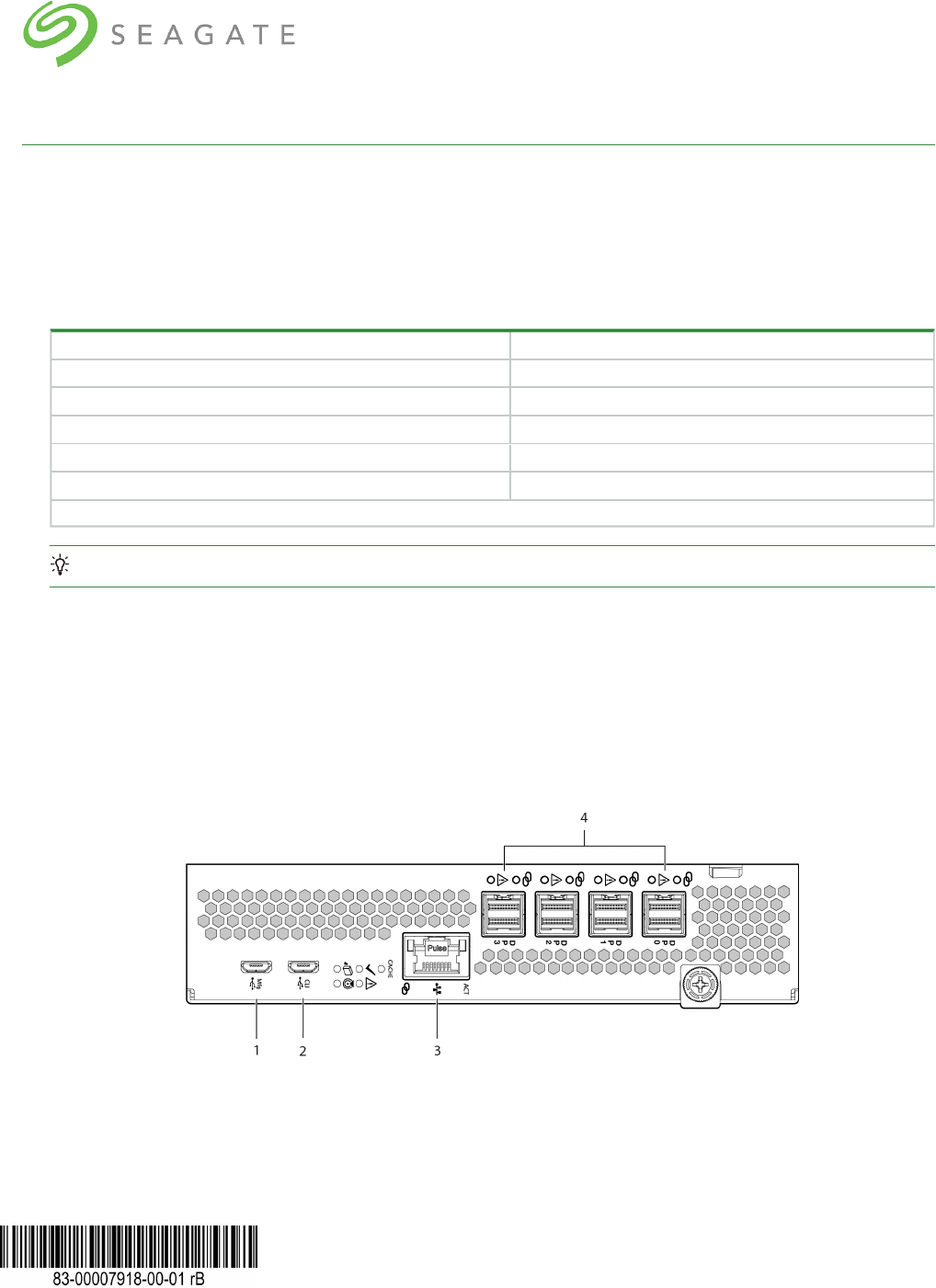
Item Description
1 Manufacturing service port: Do not use
2 Serial USB port for use with supplied serial cable
3 Ethernet port for connection to management host
4 SAS data ports for data exchange
Figure 1 Ports on sample controller module
NOTE If the management host does not recognize the new controller or the connection, it cannot communicate with it.
All setup and configuration tasks identified in this section assume you have a direct connection between the management
host and the controller using the supplied or a known good serial cable. The connection you establish is an out-of-band
connection, since it does not use a data path to transfer information between the controller and the management host.
The host computer or server can be either Linux- or Windows-based. Certain operating systems require a special mode of
operation or the installation of a device driver.
Install a device driver
Some operating systems, such as a Windows OS that predates Windows 10/Server 2016, require download and installation of a
device driver before the OS recognizes the USB device and can connect to a controller module.
To install a device driver:
1. Navigate to https://www.seagate.com/support/systems/general-support/ and locate the device driver for download.
2. Download the zip file to the management computer.
3.
Unzip the file, then click Setup.exe.
4. Follow all install instruction dialogs, clicking the prompts to run, accept, and install the device driver.
5. After successful completion of the install, close the dialog.
6. (Optional) Reset the management computer if required to complete installation and recognize the device driver.
Configure the management host for serial communication
After you successfully connect the supplied serial cable to the controller module, the management host should detect a new
USB device. The next step is to establish communication between the management host and the controller module.
Once you successfully install and run a supported terminal emulator, the controller presents a single serial port that uses the
related USB vendor identification (ID) and product ID hex codes.
Operating system Supported application
Microsoft Windows (all versions) HyperTerminal, TeraTerm, PuTTY
Linux (all versions) Minicom
Table 2 Supported terminal emulator applications
USB vendor identification code type Hex code
USB vendor identification code 0x210C
USB product identification code 0xA4A7
Table 3 Terminal emulator serial port hex codes
2
3
Configure Linux for serial communication
If you do not have a terminal emulator, such as Minicom, you must obtain one prior to completion of this task.
To configure Linux for serial communication:
IMPORTANT While Linux systems do not require installation of a device driver, it might require USB parameters as you
load the device driver to enable controller recognition.
modprobe usbserial vendor=0x210c product=0xa4a7 use_acm=1
You may also choose to incorporate the same information into the /etc/modules.conf file.
1. Determine if the operating system recognizes the USB (ACM) device by entering a command:
cat /proc/devices |grep -i "ttyACM"
If the OS discovers a device driver, it responds with the device number followed by ttyACM, for example:
116 ttyACM
2. To query the system about USB buses and the devices connected to them, use the list USB command:
lsusb
If the OSdiscovers a USB device driver, it responds with the single serial port, using the USB parameter hex codes:
ID 210c:a4a7
This confirms that the appropriate USB (ACM)device is visible to the management computer.
3. Invoke Minicom to configure it.
minicom -s
4.
Select Serial Port Setup from the menu.
5. Select the parameter setting you want to change at the prompt by typing the related setting letter (A-G).
Setting Description Parameter settings
A Serial device /dev/ttyACM0
B Lockfile location /var/lock
C Callin program
D Callout program
E Bps/Par/Bits 11520 8N1
F Hardware flow control No
G Software flow control No
Table 4 Sample Linux Minicom serial port parameter settings
6. Press the ESC key to shift from the parameters to the configuration menu.
7.
Select Save setup as dfl to save the parameter settings to default.
8.
Select Exit from Minicom.
Configure Windows for serial communication
Use the terminal emulator to launch the device driver window and directly communicate with each controller module, after
meeting the following prerequisites:

l
An installed and tested terminal emulator.
l
An installed and tested Windows USB device driver to connect to the controller module USB port, by using the native
USBserial driver for Windows 10/Server 2016 or higher, or by downloading and installing the Seagate device driver.
To configure Windows for serial communication:
1. Start and configure the terminal emulator, using the specified settings.
Parameter Value Parameter Value
Connector COM3¹ Parity None
Baud rate 115,200 Stop bits 1
Data bits 8 Flow control None
¹ Your configuration determines the COM port used for USB connection. Verify you have the correct COM port.
Table 5 Terminal emulator port connection settings
2. In the terminal emulator, right-click on the connected and identified COM port and select Enable.
NOTE You must disable XON/XOFF when using Windows 10/Server 2016 with PuTTy so you can open the COMport.
3. For any hung connection, take the following corrective actions:
a. Validate the terminal emulator configuration is correct and you selected the correct COMport.
b. Quit the terminal emulator program.
c. In the Windows Device Manager window, right-click on the problem COM port and select Disable.
d. Confirm the COM port disabled status.
e. Right-click on COM port you just disabled and select Enable to re-enable it.
f. Start the terminal emulator program again and connect to the COM port, then validate the port settings again.
Connect to a controller module for configuration
When you first install a storage enclosure, you must perform some initial tasks to connect to and configure the system, such as
setting up a user, log in, and setting a valid IP address for each controller module (CM) serial COM port.
You have three options for setting up a network, each a viable approach to the same goal: connection to the CM.
l
Use a direct connection to the serial COM port to access the Storage Management Console (SMC).
l
Use a remotely connected network to access the SMC and connect to the CM through the identified factory default
IPaddresses.
l
Use secure shell (SSH) to access the SMC at the identified factory default IP addresses.
> ssh 10.0.0.2
If the CM default IP address is not compatible with your network, you must manually set a valid IP address for each network
port, once you have a good serial port connection to the management host.
4

5
IP version Controller 0A addresses Controller 0B addresses
IPv4
IP address: 10.0.0.2 IP address: 10.0.0.3
IP subnet mask: 255.255.255.0 IP subnet mask: 255.255.255.0
Gateway IP address: 10.0.0.1 Gateway IP address: 10.0.0.1
IPv6
Autoconfig: Enabled Autoconfig: Enabled
Gateway: :: Gateway: ::
Link-Local Address: fe80::2c0:ffff:fe44:952f Link-Local Address: fe80::2c0:ffff:fe44:7010
Autoconfig IP: 6::2c0:ffff:fe44:952f Autoconfig IP: 6::2c0:ffff:fe44:7017
Table 6 Factory default network port IP addresses
To connect to a controller module for configuration:
1. Connect a serial cable from your management host to the CLI port on one of the CMs.
2. Launch the terminal emulator software and enable the CLI port for subsequent communication.
3. Press Enter to access the CLI prompt.
4.
At the prompt, login with setup, press Enter, then press Enter again at the password prompt, for example:
System Version: S100R009
OS Version: SPM100R009-01
MC Version: SXM100R009-01
Serial Number: 00C0FF535A86
SEAGATE00C0FF527EB8B login: setup
Password:
5. For first time access to the SMC, enter Y at the prompt to continue.
6. To log in at the prompt, choose from one of the following actions:
a.
For first time access, create a user, such as manage, and follow the on-screen directions to create a user account. After
doing so, the session will expire, and you can log in as the user you just created.
b. For all subsequent log in activity, log in using valid system user credentials.
7. At the prompt, type the following command to set the IP address for each controller module or both controller modules:
set network-parameters ip <address> netmask <netmask> gateway <gateway> controller a|b
where:
<address> is the IP address of the controller
<netmask> is the subnet mask
<gateway> is the IP address of the subnet router
a|b specifies the controller whose network parameters you are setting
For an ipV4 static example:
# set network-parameters ip 192.168.0.10 netmask 255.255.255.0 gateway 192.168.0.1
controller a
# set network-parameters ip 192.168.0.11 netmask 255.255.255.0 gateway 192.168.0.1
controller b
For a DHCP example:
# set network-parameters dhcp controller a
# set network-parameters dhcp controller b
NOTE See the CLI Reference Guide for information about IPv6, and the commands used to add IPv6 addresses and set
IPv6 network parameters. The ipv6 term is included within each relevant command name.
8. Choose one of the following actions to verify the new IP address:
a.
For IPv4, use the show network-parameters command.
b.
For IPv6, use the show ipv6-network-parameters command.
The result for each controller includes the IP address, subnet mask, and gateway address.
9. In the host computer's command window, first ping controller 0A and then controller 0B to verify connectivity.
ping <controller-IP-address>
10. When you are done using the CLI, exit the terminal emulator.
11. Retain the new IP addresses to access and manage the controllers by using either the SMC or the CLI.
If you cannot access your system after changing the IP address and waiting up to two or three minutes, your network
might require you to restart each affected Management Controller (MC) connected to the serial port. When you restart an
MC, you temporarily lose communication with the MC until it successfully returns to a ready state.
12. (Optional) To restart the management controller on both controllers, type the following command :
restart mc both
If you lose communication with the CLI while using an out-of-band cable connection, you can often restore communication by
disconnecting and reattaching the serial cable.
After you initially set a controller IP address and have a functioning connection, you can change it later using the SMC.
IMPORTANT Changing IP settings can cause management hosts to lose access to the storage enclosure.
Storage Management Console usage
Seagate provides a user-friendly interface that provides the means to configure, monitor, and manage the storage system: the
Storage Management Console (SMC). Access it through a supported browser, then use it to complete initial configuration of
the management host, then monitor and manage the storage enclosure.
Browser Version
Microsoft Internet Explorer 11
Mozilla Firefox 68 and newer
Google Chrome 70 and newer
Apple Safari (Mac) 11 and newer
Table 7 Supported browsers
For best results, use the following guidelines:
l
Enable browser pop-up windows and set the browser to allow cookies for the related storage system IP addresses.
l
For Internet Explorer, set the browser’s local-intranet security option to medium or medium-low, and then add each
controller’s network IP address as a trusted site.
6

7
NOTE By default, your system is loaded with self-signed certificates. You should generate new self-signed certificates on
each controller, using the create certificate CLI command. Expect browser warnings about security or privacy concerns
related to self-signed or untrusted certificates or invalid certificate authorities. Bypass such warnings, if you are confident of a
secure connection. Depending on the browser and its settings, you can create a security exception to inhibit future related
warnings, despite the continued indication of an insecure connection in the browser address bar.
Access the web-based management interface
Once you successfully complete initial installation of the storage enclosure and initial configuration of the management host,
you can access the controller module's web-based management interface, the Storage Management Console (SMC). It is a
user-friendly interface that provides the means to configure, monitor, and manage the storage system.
To access the web-based management interface:
1. Launch a web browser on the computer connected to the controller module.
2. Enter the IP address of the controller module's network port, either the default address of 10.0.0.2/3 or the address you just
configured, then press Enter.
3. To log in to the SMC, perform the following actions:
a.
In the web browser address field, type https://<controller-network-port-IP-address>,such as 10.1.4.33
without any leading zeros, and then press Enter. If a login prompt does not display, confirm you entered the correct IP
address.
b. At the prompt, enter the user name and password you just created. Refer to "Connect to a controller module for
configuration" on page4.
c. Select Log In. If the user authentication fails, a message indicates if the system is unavailable or unable to authenticate
the login.
4. Familiarize yourself with the SMC, consulting the online help topics or the Storage Management Guide.
5. To end your session, select Log Out from the banner, instead of simply closing the browser.
Complete the preboard and onboard process
During your initial connection, a wizard in the Storage Management Console (SMC) guides you through the first-time setup of
your system: the preboard and onboard process. Follow the on-screen directions to complete your setup.
To complete the preboard and onboard process:
1. Complete the following actions to successfully complete the preboard process:
a. Agree at the prompt to the end-user license agreement (EULA).
b. Create your profile username and password for all future access.
c. Update the controller firmware, as required.
2. Complete the following actions to successfully complete the onboard process:
a. Configure your system settings: network settings, data and time, user definitions, and system notifications.
b. Complete the storage system configuration, choosing the key features that pertain to the storage enclosure to ensure
your storage enclosure achieves optimal capacity and performance.
c. Provision the storage enclosure by creating hosts and host groups, then creating volumes and attaching them to hosts.
3. Continue to use the SMC to monitor and manage the storage enclosure by following instructions in the related Storage
Management Guide, or use the online help.

TIP Use the QR code on the included Getting Started sheet to access related storage enclosure documentation online.
© 2022 Seagate Technology LLC or its affiliates. All rights reserved. Seagate, Seagate Technology, and the Spiral logo are registered trademarks of Seagate
Technology LLC in the United States and/or other countries. CORVAULT and Exos are either trademarks or registered trademarks of Seagate Technology LLC or
one of its affiliated companies in the United States and/or other countries. All other trademarks or registered trademarks are the property of their respective
owners. All coded instruction and program statements contained herein remain copyrighted works and confidential proprietary and trade secret information of
Seagate Technology LLC or its affiliates. Any use, derivation, disassembly, reverse engineering, dissemination, reproduction, or any attempt to modify, prepare
derivative works, reproduce, distribute, disclose copyrighted material of Seagate Technology LLC, for any reason, in any manner, medium, or form, in whole or in
part, if not expressly authorized, is strictly prohibited. Seagate reserves the right to change, without notice, product offerings or specifications.
Open source third-party licenses and code
Seagate storage products use open source software components. To view information about open source software licenses and open source code used in Seagate
storage products, see www.seagate.com/support.
8
